US3826584A - Process and apparatus for the production of connectors for space frameworks or the like - Google Patents
Process and apparatus for the production of connectors for space frameworks or the like Download PDFInfo
- Publication number
- US3826584A US3826584A US00222111A US22211172A US3826584A US 3826584 A US3826584 A US 3826584A US 00222111 A US00222111 A US 00222111A US 22211172 A US22211172 A US 22211172A US 3826584 A US3826584 A US 3826584A
- Authority
- US
- United States
- Prior art keywords
- axis
- blank
- connector
- rotation
- clamping device
- Prior art date
- Legal status (The legal status is an assumption and is not a legal conclusion. Google has not performed a legal analysis and makes no representation as to the accuracy of the status listed.)
- Expired - Lifetime
Links
Images


Classifications
-
- B—PERFORMING OPERATIONS; TRANSPORTING
- B23—MACHINE TOOLS; METAL-WORKING NOT OTHERWISE PROVIDED FOR
- B23B—TURNING; BORING
- B23B41/00—Boring or drilling machines or devices specially adapted for particular work; Accessories specially adapted therefor
-
- B—PERFORMING OPERATIONS; TRANSPORTING
- B23—MACHINE TOOLS; METAL-WORKING NOT OTHERWISE PROVIDED FOR
- B23B—TURNING; BORING
- B23B39/00—General-purpose boring or drilling machines or devices; Sets of boring and/or drilling machines
- B23B39/14—General-purpose boring or drilling machines or devices; Sets of boring and/or drilling machines with special provision to enable the machine or the drilling or boring head to be moved into any desired position, e.g. with respect to immovable work
-
- B—PERFORMING OPERATIONS; TRANSPORTING
- B23—MACHINE TOOLS; METAL-WORKING NOT OTHERWISE PROVIDED FOR
- B23Q—DETAILS, COMPONENTS, OR ACCESSORIES FOR MACHINE TOOLS, e.g. ARRANGEMENTS FOR COPYING OR CONTROLLING; MACHINE TOOLS IN GENERAL CHARACTERISED BY THE CONSTRUCTION OF PARTICULAR DETAILS OR COMPONENTS; COMBINATIONS OR ASSOCIATIONS OF METAL-WORKING MACHINES, NOT DIRECTED TO A PARTICULAR RESULT
- B23Q1/00—Members which are comprised in the general build-up of a form of machine, particularly relatively large fixed members
- B23Q1/25—Movable or adjustable work or tool supports
- B23Q1/44—Movable or adjustable work or tool supports using particular mechanisms
- B23Q1/50—Movable or adjustable work or tool supports using particular mechanisms with rotating pairs only, the rotating pairs being the first two elements of the mechanism
- B23Q1/54—Movable or adjustable work or tool supports using particular mechanisms with rotating pairs only, the rotating pairs being the first two elements of the mechanism two rotating pairs only
- B23Q1/5406—Movable or adjustable work or tool supports using particular mechanisms with rotating pairs only, the rotating pairs being the first two elements of the mechanism two rotating pairs only a single rotating pair followed perpendicularly by a single rotating pair
- B23Q1/5437—Movable or adjustable work or tool supports using particular mechanisms with rotating pairs only, the rotating pairs being the first two elements of the mechanism two rotating pairs only a single rotating pair followed perpendicularly by a single rotating pair and in which the degree of freedom, which belongs to the working surface, is perpendicular to this surface
-
- B—PERFORMING OPERATIONS; TRANSPORTING
- B23—MACHINE TOOLS; METAL-WORKING NOT OTHERWISE PROVIDED FOR
- B23Q—DETAILS, COMPONENTS, OR ACCESSORIES FOR MACHINE TOOLS, e.g. ARRANGEMENTS FOR COPYING OR CONTROLLING; MACHINE TOOLS IN GENERAL CHARACTERISED BY THE CONSTRUCTION OF PARTICULAR DETAILS OR COMPONENTS; COMBINATIONS OR ASSOCIATIONS OF METAL-WORKING MACHINES, NOT DIRECTED TO A PARTICULAR RESULT
- B23Q39/00—Metal-working machines incorporating a plurality of sub-assemblies, each capable of performing a metal-working operation
- B23Q39/04—Metal-working machines incorporating a plurality of sub-assemblies, each capable of performing a metal-working operation the sub-assemblies being arranged to operate simultaneously at different stations, e.g. with an annular work-table moved in steps
- B23Q39/042—Metal-working machines incorporating a plurality of sub-assemblies, each capable of performing a metal-working operation the sub-assemblies being arranged to operate simultaneously at different stations, e.g. with an annular work-table moved in steps with circular arrangement of the sub-assemblies
-
- E—FIXED CONSTRUCTIONS
- E04—BUILDING
- E04B—GENERAL BUILDING CONSTRUCTIONS; WALLS, e.g. PARTITIONS; ROOFS; FLOORS; CEILINGS; INSULATION OR OTHER PROTECTION OF BUILDINGS
- E04B1/00—Constructions in general; Structures which are not restricted either to walls, e.g. partitions, or floors or ceilings or roofs
- E04B1/18—Structures comprising elongated load-supporting parts, e.g. columns, girders, skeletons
- E04B1/19—Three-dimensional framework structures
- E04B1/1903—Connecting nodes specially adapted therefor
- E04B1/1906—Connecting nodes specially adapted therefor with central spherical, semispherical or polyhedral connecting element
-
- E—FIXED CONSTRUCTIONS
- E04—BUILDING
- E04B—GENERAL BUILDING CONSTRUCTIONS; WALLS, e.g. PARTITIONS; ROOFS; FLOORS; CEILINGS; INSULATION OR OTHER PROTECTION OF BUILDINGS
- E04B1/00—Constructions in general; Structures which are not restricted either to walls, e.g. partitions, or floors or ceilings or roofs
- E04B1/18—Structures comprising elongated load-supporting parts, e.g. columns, girders, skeletons
- E04B1/19—Three-dimensional framework structures
- E04B2001/1957—Details of connections between nodes and struts
- E04B2001/196—Screw connections with axis parallel to the main axis of the strut
-
- Y—GENERAL TAGGING OF NEW TECHNOLOGICAL DEVELOPMENTS; GENERAL TAGGING OF CROSS-SECTIONAL TECHNOLOGIES SPANNING OVER SEVERAL SECTIONS OF THE IPC; TECHNICAL SUBJECTS COVERED BY FORMER USPC CROSS-REFERENCE ART COLLECTIONS [XRACs] AND DIGESTS
- Y10—TECHNICAL SUBJECTS COVERED BY FORMER USPC
- Y10S—TECHNICAL SUBJECTS COVERED BY FORMER USPC CROSS-REFERENCE ART COLLECTIONS [XRACs] AND DIGESTS
- Y10S408/00—Cutting by use of rotating axially moving tool
- Y10S408/01—Bowling ball drill
-
- Y—GENERAL TAGGING OF NEW TECHNOLOGICAL DEVELOPMENTS; GENERAL TAGGING OF CROSS-SECTIONAL TECHNOLOGIES SPANNING OVER SEVERAL SECTIONS OF THE IPC; TECHNICAL SUBJECTS COVERED BY FORMER USPC CROSS-REFERENCE ART COLLECTIONS [XRACs] AND DIGESTS
- Y10—TECHNICAL SUBJECTS COVERED BY FORMER USPC
- Y10T—TECHNICAL SUBJECTS COVERED BY FORMER US CLASSIFICATION
- Y10T408/00—Cutting by use of rotating axially moving tool
- Y10T408/36—Machine including plural tools
- Y10T408/37—Turret of tools
-
- Y—GENERAL TAGGING OF NEW TECHNOLOGICAL DEVELOPMENTS; GENERAL TAGGING OF CROSS-SECTIONAL TECHNOLOGIES SPANNING OVER SEVERAL SECTIONS OF THE IPC; TECHNICAL SUBJECTS COVERED BY FORMER USPC CROSS-REFERENCE ART COLLECTIONS [XRACs] AND DIGESTS
- Y10—TECHNICAL SUBJECTS COVERED BY FORMER USPC
- Y10T—TECHNICAL SUBJECTS COVERED BY FORMER US CLASSIFICATION
- Y10T408/00—Cutting by use of rotating axially moving tool
- Y10T408/55—Cutting by use of rotating axially moving tool with work-engaging structure other than Tool or tool-support
- Y10T408/561—Having tool-opposing, work-engaging surface
- Y10T408/5614—Angularly adjustable surface
-
- Y—GENERAL TAGGING OF NEW TECHNOLOGICAL DEVELOPMENTS; GENERAL TAGGING OF CROSS-SECTIONAL TECHNOLOGIES SPANNING OVER SEVERAL SECTIONS OF THE IPC; TECHNICAL SUBJECTS COVERED BY FORMER USPC CROSS-REFERENCE ART COLLECTIONS [XRACs] AND DIGESTS
- Y10—TECHNICAL SUBJECTS COVERED BY FORMER USPC
- Y10T—TECHNICAL SUBJECTS COVERED BY FORMER US CLASSIFICATION
- Y10T408/00—Cutting by use of rotating axially moving tool
- Y10T408/60—Plural tool-assemblages
Definitions
- - blank is then engaged by its through hole in a clamping device that is rotatable along the axis of the through hole, the clamping device being mounted on an element that is rotatable on an axis at right angles to the axis of the through hole and which intersects the axis of the through hole at right angles.
- Tool means positioned adjacent the clamp to work on the blank engaged thereby operate along an axis disposed perpendicular to thefirst two mentioned axes, the tool means being operative to machine the blank at fixed spatial positions to which the blank is adjusted by movement about the first two axes, the tool means boring holes in the blank, machining flats around said holes at right angles to the holes and tapping the holes.
- the tool means are moved relative to the clamping device and the connector blank about a further axis common to the tool means and the clamping device.
- the connector blank is then positioned to a new predetermined spatial position by the clamping device and the tool I means produce another hole while the blank is maintained in the original clamping device by its through f-hole whereby a plurality of accurate spaced holes are produced in theconnector blank.
- This invention relates to a process and apparatus for the production of connectors for space frameworks or the like, particularly polyhedral connectors, wherein a connector blank is held in a clamping device and provided with tapped holes, the axes of which intersect in the center of the connector.
- connectors are spherical or polyhedral bodies of 'a superstrength material which are provided with a number of concentric threaded holes of extreme accuracy for the threaded connection of rods and other structural elements for the manufacture of space frameworks.
- Space frameworks of different space configurations and static relationships require connectors of a great variety of types. Therefore, one
- the manufacturing method customary heretofore consists in providing, for each type of connectors, several operating steps in series and in changing, between the operating steps, not only the cutting tools but also the clamping devices for the connector blanks, i.e. the connector blank is in each case repeatedly clamped into position for individual partial working steps.
- standard connectors with 18 tapped connectingholes are manufactured by dimensionally milling, in a first operating step, the necessary surfaces ata spherical connector blank; conducting the necessary drilling operations in a second operating stepiand tapping the holes in a third operating step.
- This process has the advantage that, with a single clamping/of the connector blank in its through hole axis, all of the required operating steps to manufacture connectors of a great variety of types can be continuously conducted on one and the same apparatus by a single operator. Since the clamping condition of the connector blank is not changed between the individual processing steps, and the connector blank can be placed into any desired spatial positions and fixed therein for machining, an automatic, forexample numerical control of the operating steps is also advantageously possible.
- the machining of the'connectorblank has been so much simplified by the process of the present invention that the necessary operating steps can be effected even in case of connectors of up to 26 tapped connecting bores within a relatively short period of time.
- Process step (b) ensures, on the one hand, that the axes of all tapped connecting bores intersect in the center of the connector and makes it possible, on the other hand, in conjunction with process step (c) to form varying angles between the individual threaded connecting bores.
- the connectors are placed into a great variety of different spatial positions while maintaining a single clamping for providing the tapped connecting bores.
- process step (d) makes it possible, inter alia, to produce economically, for example,different threaded connecting bores at one and the same work station in a continuous operating sequence.
- a further embodiment of the process of this invention resides in that several connector blanks are clamped into a clamping device at a lateral spacing from one another in their through hole axes in such a manner that their axes intersect the axis of rotation of the clamping device, and that the connector blanks are adjusted into the various spatial positions alternatingly by the common rotation of the connector blanks about the axes of their through holes and about the axis of rotation of the clamping device commonly associated with the connector blanks, and the connector blanks are simultaneously machined in the fixed spatial positions along the axes of several tools.
- the advantage is attained that several connector blanks can be processed together in different fixed spatial positions simultaneously by several tools. This further increases the economy of the connector production.
- the advantage is obtained that the angles between the individual threaded connecting bores can be of individual character and different, and that also the thread diameters at the same connector can vary from one tapped hole to the other. Furthermore, this mode of operation makes it possible to use multiplespindle machining units for the simultaneously provision of numerous threaded connecting holes at the various connector blanks.
- the length termination'of the individual tapped holes can be derived from the length termination of the through hole by truncating or countersinking of the connector blank.
- This derivation of the length termination can be effected in a mechanical, electrical, or opticoelectrical manner, wherein the feed of the tools along the tool axes is automatically limited in such a manner that all of the tapped connecting holes of the finished connector exhibit the same length.
- the apparatus for conducting the manufacturing process for connectors is characterized by a bearing block on which is mounted a head with a circular base to be rotatable about an axis, exhibiting two arms diametrically disposed at the circular base and projecting therefrom in a vertical or almost vertical direction, the clamping device for the connector blank, which device is rotatable about its axis, being supported in these arms in such a manner that the two axes of rotation of the clamping device intersect in a point with the further axis of a tool, which latter axis is preferably oriented perpendicularly to one of the axes of rotation of the clamping device.
- This apparatus is structurally simple and makes it possible, with a single clamping of the connector blank in the axis of its through hole, to effect the required adjustment of the connector blank into the various spatial positions for executing the required machining operations.
- Another apparatus for conducting the process of this invention is characterized in that the clamping device for the connector blank, which is adjustable about its axis of rotation, is provided with its axis of rotation on a diameter of a ring, the internal diameter of which is larger than the outer diameter of a connector blank,
- this ring being suspended to be rotatable about a further axis of rotation intersectingwith one of the axes of rotation of the clamping device and with the further axis of a tool in one point, wherein the tool axis is preferably disposed perpendicularly on one of the axes of rotation of the clamping device.
- This apparatus is likewise distinguished by structural simplicity and universal usability for the production of connectors of a great variety of types (so-called standard connectors and special connectors).
- a system of tools associated with the clamping device is provided, with an axis of rotation about which the tools are adjustable in such a manner that their axes intersect alternatingly the axes of rotation of the clamping device in a point, the axes of the tools being disposed in parallel to the axis of rotation of the tool system.
- the clamping device can also be arranged to be to.- tatably movable about a system of fixed tools disposed along a circular path, the center of which is congruent with the axis of rotation of the clamping device.
- clamping devices can be mounted at spacings from one another in an annular arrangement on an indexing table which rotates intermittently about an axis
- a plurality of machining units can be fixedly disposed in an annular arrangement on the periphery of the indexing table, the tool axes of these machining units intersecting the axis of rotation of the indexing table.
- This arrangement is preferred if the diameter ofthe entire apparatus is to be kept as small as possible.
- several clamping devices for connector blanks can be mounted in series laterally at mutual spacings and m tatable about their axes on a support rotatable about a further axis, wherein the axes of the clamping devices intersect the axis of rotation of the support under a right angle.
- a common drive can be associated with the clamping devices, and a machining unit can be provided at a spacing of the clamping devices, the tool axes of which intersect the axis of a clamping device and the axis of rotation of the support in each instance in one point.
- FIG. 2 is a perspective view of a polyhedral (standard) connector with 18 tapped connecting bores;
- FIG. 3 is a perspective view of a (special) connector with only eight tapped connecting bores
- FIG. 4 is a view of a connector similar to FIG. 3, this connector exhibiting respectively four tapped connecting bores on the corresponding junction surfaces;
- FIG. 5 is a perspective view of another (special) connector with several tapped connecting bores, the axes of which form differing angles;
- FIGS. 5a shows the axial arrangement of the tapped connecting bores, based on FIG. 5 but in one plane for the sake of clarity;
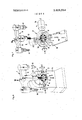
- FIG. fi shows a schematic perspective view of one embodiment of a combined clamping device and machining unit for connectors
- FIG. 7 is a schematic perpsective view of another embodiment of a combined clamping device and machining unit for connectors
- FIG. 8 is a schematic top view of a device with an indexing table carrying several clamping devices for connector blanks cooperating with fixed machining units on the periphery of the indexing table;
- FIG. 9 is a schematic perspective view of a multipleway clamping device for connector blanks, wherein several parts have been omitted for the sake of clarity, in conjunction with a schematically indicated machining unit;
- FIG. 10 shows, partially in section and on a reduced scale, three schematic lateral views of the apparatus illustrated in FIG. 9 in its numerous different setting positions;
- FIG. 11 is a schematic plan view of an indexing table carrying several sets of multiple-way clamping devices according to FIG. 9 cooperating with corresponding stationary machining units on the periphery of the indexing table.
- FIGS. 1-5 several different connectors are shown, partially in a schematic view, all ofwhich can be manufactured in accordance with the process of this invention with extreme precision in one and the same apparatus in a fully automatic manner.
- this invention is not limited to these connectors illustrated in the drawings.
- FIG. 1 shows schematically a polyhedral connector blank with 26 faces and axes of symmetry, the axes being denoted as customary in crystal science; as a finished connector, this article is suitable for space frameworks in accordance with the system of the bodycentered cube as well as in accordance with the system of the face-centered cube.
- FIG. 2 illustrates a connector with 18 tapped connecting bores of equal diameter for space frameworks frequently employed in practice, solely in the system of the face-centered cube.
- the connector shown in FIG. 3 is intended exclusively for space frameworks of half octahedrons and tetrahedrons and thus exhibits, in addition to the through hole with the axis Zv wherein the clamping is effected, only 8 threaded connecting holes at regular angular spacings.
- FIG. 4 shows basically the same: structural shape of a connector as illustrated in FIG. 3; however, in each connecting face of the polyhedral connector, four tapped connecting bores for rod connections with a multiple screw joint (not shown) are provided.
- Connectors according to FIG. 5 for use in singlelayer geodesic domes possess several tapped connecting bores, four of these being shown in this embodi ment, the axes A, A of which form different angles 4), d), with respect to the through hole axis Z (axis of the receiving bore) and different angles 4), (b, with one another (see FIG. 5a).
- FIG. 6 a relatively simple combined machining unit 1 and clamping device 2 can be seen. with a polyhedral connector 3 exhibiting 18 tapped connecting bores 4 and corresponding to the connector shown in FIG. 2.
- the clamping device 2 contains a bearing block 5 at which a head with a circular base 6 is mounted to be rotatable about an axis II.
- Diametrical and approximately vertically projecting arms 7., 7 are mounted to the circular base 6; the holding elements 8, 8 for the connector blank are, in turn, mounted in these arms so that they are rotatable in the axis l and are axially adjustable.
- the connector blank is first provided with a through tap hole extending at least through the approximate center thereof and with truncated areas at the bore openings at right angles to the drilling axis I; with the aid of the holding elements 8, 8, the blank is clamped or centered in this axis I in such a manner that its center is congruent with the point of intersection of the axes I, II, and a tool axis 111 which will be explained hereinbelow.
- the truncated areas also serve to define the length of the tapped through hole and are provided at equal spacings with respect to the center of the connector blank.
- the holding elements 8, 8 and the circular base 6 are correspondingly rotated about their axes l and II, respectively. and fixed in the individual machining positions.
- the holding elements 8, 8 and the cireular base 6 can be operated by conventional drive means, for example in an electrical, mechanical, hydraulic, or pneumatic manner.
- the axes of rotation I and II form a right angle with each other, and the tool axis III is disposed perpendicularly on the axis of rotation II.
- the machining unit 1 exhibits a three-armed crosshead 9 rotatable about an axis of rotation IV; a shank face miller 10, a twist drill 11, and a tap 12 are mounted at this crosshead, each having its own electromotive drive M.
- the arrangement is such that the axis of rotation IV extends in parallel to the tool axis III, and the various tools 10, 11, and 12 are adjustable in the required succession in such a manner that their axes intersect alternatingly in one point along the illustrated axis III with the axes of rotation I and II.
- the rotation of the crosshead 9 for the positioning ofthe respective tools can be effected, for example, by means of an electric servomotor (not shown) which can be numerically controlled, just as the drive and feed ofthe individual tools, namely in conformance with the movements of the clamping device 2.
- the advance of the shank face miller can furthermore be derived, for example by electrical means. from the length termination of the connector blank along the axis I of the through hole.
- the holding elements 8, 8' are mounted in a ring 13 to be rotatable and axially adjustable in such a manner that their axis of rotation I lies on a diameter of the ring.
- the rotation of the holding elements 8, 8 and thus of the connector blank clamped therein about the axis I is caused by an electric servomotor 14 flanged to the ring 13.
- the ring 13, in turn, is suspended at bearing brackets 15, 16 so that it is rotatably movable about an axis of rotation II.
- An electric servomotor l7 flanged 8 to the bearing bracket 16 effects the rotation of the ring 13 about the axis II.
- the arrangement of the axes I, II, III, and IV corresponds to that shown in FIG. 6.
- FIG. 8 shows schematically l2 clamping devices 20 of a construction as illustrated, for example. in FIG. 6 or in FIG. 7. These clamping devices are mounted at spacings from one another in an annular arrangement on an indexing table 21 rotatable about an axis IV.
- machining units M1 M10 are fixedly disposed in this embodiment on the periphery of the indexing table 21.
- the tool axes III of these machining units intersect the axis of rotation IV of the indexing table at a right angle.
- the connector blanks 24 fed at E are clamped and centered in a clamping device 20, while the finished connectors 25 are released from the individual clamping devices at station 23 and are discharged at A.
- the indexing table 21 is rotated intermittently, so that the machining units Ml through M10 can be simultaneously employed selectively, with the indexing table being at a standstill.
- the machining units are preferably designed for the largest applicable tapped connecting hole.
- the machining units are also possible to fashion almost all, or only a few, of the machining units as multiple-spindle drilling heads for simultaneous drilling and thread cutting.
- the individual machining units Ml through M10 are each equipped with a specific tool.
- the connector blanks are spatially adjustable in a single or multiple fashion in their clamping devices 20 at the respective work stations during standstill of the indexing table.
- the operating sequence generally also comprises in this instance not considering the feeding and discharging of the connector blanks and finished connectors, respectively the operations of centering, drilling, milling of the contact surfaces, and cutting of the thread.
- machining units and/or operating stations by the way, depends on the number of differently large threaded connecting bores and additional partial operating steps, such as, for example, centering, milling of the contact surfaces, and preliminary drilling.
- the device of FIG. 8 is under numerical control, in such a manner that a correct coordination is provided for the indexing steps of the indexing table from one machining unit and/or station to the next, well as for the actuation and shutdown of the individual machining units and finally also or the ad- 9. justing motions of the clamping nector blanks.
- a correct coordination is provided for the indexing steps of the indexing table from one machining unit and/or station to the next, well as for the actuation and shutdown of the individual machining units and finally also or the ad- 9. justing motions of the clamping nector blanks.
- the machining units M1 through M10 can also be provided with turret heads.
- a turret head of one machining unit can equip tools for the centering, drilling, milling, and thread cutting operations.
- a connector can be produced with ID tapped connecting bores wherein the thread diameters and angles differ from one bore to the next. The total manufacturing time for such special connectors is thereby reduced to an absolute minimum.
- the apparatus of FIG. 8 is consequently suitable for an economical mass production of connectors of a great variety of types. In this connection, one operator can advantageously operate, monitor, and centrally control simultaneously several ones of such apparatus.
- the machining units can also be fixedly disposed circularly above the path of motion of the clamping device, so that the axes III thereof extend in parallel or approxidevices 20 for the conmately in parallel to the axis of rotation IV of the indexing table 21.
- FIG. 9 shows an embodiment of a multiple-way clamping device 30 capable of receiving three connector blanks 3 for simultaneous processing in different, fixed positions in space.
- the apparatus comprises a bearing disk 32 mounted in a bearing block 31, as well as a ratchet wheel 33 to which a stub shaft 34 is attached, the latter being supported in a schematically indicated bearing block 35 which can be connectedwith the bearing block 31.
- the two disks 32, 33 are joined by an angle plate. 36 serving as the support and are rotatable about the axis II by way of an electric servomotor37 and a pinion 38.
- the multiple-way clamping device can be placed, for example, into the different adjusting positions shown in FIG. wherein the connector blanks assume correspondingly individual spatial positions.
- the holding elements for the connector blanks 3 consist, in this embodiment, of a lower centering plug 39 and an upper centering plug 40, between which a connector blank can be clamped in the axis I of its through hole.
- the upper plugs 40 are attached to arms 41 pivotably mounted in the angle plate 36; these arms can be operated, for example, by pneumatic or hydraulic devices which are not shown.
- lower centering plugs 39 are rotatably mounted on axle stubs 42 aligned with the axesI/l, U2, and U3.
- the lower centering plugs are furthermore provided with a worm gear tooth system 43 meshing with a worm shaft 44 rotatably mounted in the disks 32, 33; this worm shaft, in turn, is rotatable by means of an electric servomotor 45 flanged to the bearing disk 32.
- a machining unit 46 is associated with the multiple- I way clamping device 30; the tool axes III/1, III/2, and III/3 of this unit intersect in each case the individual axes U1, U2, and U3 and the axis of rotation II in the individual, above-mentioned points.
- the machining unit 46 can be fashioned to be rotatable, similarly to the machining units 1 and 1 of FIGS. 6 and 7, respectively, and can contain a set of twist drills, shank face millers, and taps.
- the control of the multiple-way clamping device 30, the various-drive means thereof, and the machining unit 46 can likewise be designed as a numerical control.
- FIG. 1 1 shows an apparatus similar to that of FIG. 8, with an indexing table 21 rotatable about an axis IV, on which l2 multiple-way clamping devices 30 according to FIG. 9 are arranged in a circular manner and at equal spacings from one another.
- l0 machining units Ml M10 are fixedly disposed in such a manner that their tool axes III/l, III/2, and III/3 intersect the axes of rotation I and II of the individual clamping devices 39,
- the clamping devices can also be fixedly disposed and the machining units can be rotatably mounted on an annular support about the axis IV.
- the abovedescribed relative motions are basically reversible, which also holds true for all movements about the. various axes.
- additional movements about further axes are possible in addition to the motions about the axes I through IV.
- the machining units can be rotated about the axis IV and additionally can be pivoted about further axes disposed in space in any desired manner.
- Apparatus for producing accurately spaced holes in spherical and polyhedral connector blanks having a through bore comprising a bearing block, a head having a base plate rotatably mounted on said bearing having an axis of rotation (IV) about which the plurality of tools are adjustable in such a manner that said further axis (III) of each tool alternatingly intersects the axes of rotation (l and II) of said base plate and clamping means in one point, wherein the further axes (III) of said plurality of tools are arranged in parallel to the axis of rotation (IV) of the tool system.
Landscapes
- Engineering & Computer Science (AREA)
- Mechanical Engineering (AREA)
- Architecture (AREA)
- Physics & Mathematics (AREA)
- Electromagnetism (AREA)
- Civil Engineering (AREA)
- Structural Engineering (AREA)
- Drilling And Boring (AREA)
Priority Applications (6)
| Application Number | Priority Date | Filing Date | Title |
|---|---|---|---|
| US00440183A US3841783A (en) | 1971-02-08 | 1974-02-06 | Apparatus for the production of connectors for space frameworks or the like |
| US00440187A US3841784A (en) | 1971-02-08 | 1974-02-06 | Apparatus for the production of connectors for space frameworks or the like |
| US00440184A US3841781A (en) | 1971-02-08 | 1974-02-06 | Apparatus for the production of connectors for space frameworks or the like |
| US00440185A US3850540A (en) | 1971-02-08 | 1974-02-06 | Apparatus for the production of connectors for space frameworks or the like |
| US00440181A US3841780A (en) | 1971-02-08 | 1974-02-06 | Process for the production of connectors for space frameworks or the like |
| US00440186A US3841782A (en) | 1971-02-08 | 1974-02-06 | Apparatus for the production of connectors for space frameworks or the like |
Applications Claiming Priority (1)
| Application Number | Priority Date | Filing Date | Title |
|---|---|---|---|
| DE2105824A DE2105824C3 (de) | 1971-02-08 | 1971-02-08 | Vorrichtung zum Einspannen von Werkstücken für das Bearbeiten an mehreren Umfangsflächen |
Publications (1)
| Publication Number | Publication Date |
|---|---|
| US3826584A true US3826584A (en) | 1974-07-30 |
Family
ID=5798119
Family Applications (1)
| Application Number | Title | Priority Date | Filing Date |
|---|---|---|---|
| US00222111A Expired - Lifetime US3826584A (en) | 1971-02-08 | 1972-01-31 | Process and apparatus for the production of connectors for space frameworks or the like |
Country Status (10)
| Country | Link |
|---|---|
| US (1) | US3826584A (OSRAM) |
| AT (1) | AT316084B (OSRAM) |
| CA (1) | CA950179A (OSRAM) |
| CH (1) | CH556715A (OSRAM) |
| DE (1) | DE2105824C3 (OSRAM) |
| FR (1) | FR2126749A5 (OSRAM) |
| GB (1) | GB1346736A (OSRAM) |
| IL (1) | IL38709A (OSRAM) |
| IT (1) | IT947219B (OSRAM) |
| SE (1) | SE379952B (OSRAM) |
Cited By (7)
| Publication number | Priority date | Publication date | Assignee | Title |
|---|---|---|---|---|
| US5141368A (en) * | 1990-03-20 | 1992-08-25 | Worldwide Medical Plastics Inc. | Automated side-drilled device and method for catheters |
| US5427478A (en) * | 1993-09-30 | 1995-06-27 | John N. Boucher | Bowling ball drilling apparatus |
| US5732937A (en) * | 1996-03-06 | 1998-03-31 | Morghen; Manfred A. | Workpiece indexing and clamping system |
| US5909988A (en) * | 1996-10-10 | 1999-06-08 | Deckel Maho Gmbh | Universal combined milling and boring machine |
| US20070251071A1 (en) * | 2006-05-01 | 2007-11-01 | Mori Seiki Co., Ltd. | Machine Tool |
| CN109227280A (zh) * | 2018-08-23 | 2019-01-18 | 江苏大学 | 一种球面副表面加工装置及其方法 |
| CN113581398A (zh) * | 2021-09-07 | 2021-11-02 | 哈尔滨工业大学(深圳) | 一种可快速装配的多杆节点 |
Families Citing this family (4)
| Publication number | Priority date | Publication date | Assignee | Title |
|---|---|---|---|---|
| DE2934571A1 (de) * | 1979-08-27 | 1981-03-12 | Burr, Hartfried, Ing.(grad.), 7120 Bietigheim-Bissingen | Werkzeugmaschine mit einem werkstuecktroeaeger und mehreren um den werkstuecktraeger angeordneten bearbeitungseinheiten |
| FR2560541B1 (fr) * | 1984-03-02 | 1987-06-26 | Sateco Sarl | Machine executant diverses operations d'usinage, telles que tournage, fraisage, alesage |
| IL74479A (en) * | 1984-11-01 | 1994-04-12 | Koor Metal Ltd | Connects rods to create a spatial structure |
| FR2585276B2 (fr) * | 1985-07-26 | 1987-11-13 | Sateco Sarl | Machine executant diverses operations d'usinage telles que tournage, fraisage, alesage |
Citations (4)
| Publication number | Priority date | Publication date | Assignee | Title |
|---|---|---|---|---|
| US342285A (en) * | 1886-05-18 | crowell | ||
| US1530819A (en) * | 1922-04-18 | 1925-03-24 | Orville H Ensign | Multiple-drill press |
| US3271870A (en) * | 1964-03-17 | 1966-09-13 | David P Blaker | Bowling ball hole gauging device |
| US3382740A (en) * | 1965-12-29 | 1968-05-14 | Russell P. Lotta | Ball drilling machine |
-
1971
- 1971-02-08 DE DE2105824A patent/DE2105824C3/de not_active Expired
-
1972
- 1972-01-13 CH CH53472A patent/CH556715A/xx not_active IP Right Cessation
- 1972-01-14 AT AT33672A patent/AT316084B/de active
- 1972-01-31 US US00222111A patent/US3826584A/en not_active Expired - Lifetime
- 1972-02-02 IT IT20110/72A patent/IT947219B/it active
- 1972-02-07 SE SE7201389A patent/SE379952B/xx unknown
- 1972-02-07 FR FR7203986A patent/FR2126749A5/fr not_active Expired
- 1972-02-07 GB GB563872A patent/GB1346736A/en not_active Expired
- 1972-02-08 IL IL38709A patent/IL38709A/xx unknown
- 1972-02-08 CA CA134,198,A patent/CA950179A/en not_active Expired
Patent Citations (4)
| Publication number | Priority date | Publication date | Assignee | Title |
|---|---|---|---|---|
| US342285A (en) * | 1886-05-18 | crowell | ||
| US1530819A (en) * | 1922-04-18 | 1925-03-24 | Orville H Ensign | Multiple-drill press |
| US3271870A (en) * | 1964-03-17 | 1966-09-13 | David P Blaker | Bowling ball hole gauging device |
| US3382740A (en) * | 1965-12-29 | 1968-05-14 | Russell P. Lotta | Ball drilling machine |
Cited By (10)
| Publication number | Priority date | Publication date | Assignee | Title |
|---|---|---|---|---|
| US5141368A (en) * | 1990-03-20 | 1992-08-25 | Worldwide Medical Plastics Inc. | Automated side-drilled device and method for catheters |
| US5427478A (en) * | 1993-09-30 | 1995-06-27 | John N. Boucher | Bowling ball drilling apparatus |
| US5624215A (en) * | 1993-09-30 | 1997-04-29 | Boucher; John N. | Bowling ball drilling |
| US5732937A (en) * | 1996-03-06 | 1998-03-31 | Morghen; Manfred A. | Workpiece indexing and clamping system |
| US6039312A (en) * | 1996-03-06 | 2000-03-21 | Morghen; Manfred A. | Workpiece clamping system |
| US5909988A (en) * | 1996-10-10 | 1999-06-08 | Deckel Maho Gmbh | Universal combined milling and boring machine |
| US20070251071A1 (en) * | 2006-05-01 | 2007-11-01 | Mori Seiki Co., Ltd. | Machine Tool |
| US7356895B2 (en) * | 2006-05-01 | 2008-04-15 | Mori Seiki Co., Ltd. | Machine tool |
| CN109227280A (zh) * | 2018-08-23 | 2019-01-18 | 江苏大学 | 一种球面副表面加工装置及其方法 |
| CN113581398A (zh) * | 2021-09-07 | 2021-11-02 | 哈尔滨工业大学(深圳) | 一种可快速装配的多杆节点 |
Also Published As
| Publication number | Publication date |
|---|---|
| SE379952B (OSRAM) | 1975-10-27 |
| DE2105824A1 (de) | 1972-10-05 |
| DE2105824C3 (de) | 1974-07-04 |
| CH556715A (de) | 1974-12-13 |
| IL38709A0 (en) | 1972-04-27 |
| IL38709A (en) | 1975-02-10 |
| FR2126749A5 (OSRAM) | 1972-10-06 |
| AT316084B (de) | 1974-06-25 |
| CA950179A (en) | 1974-07-02 |
| GB1346736A (en) | 1974-02-13 |
| IT947219B (it) | 1973-05-21 |
| DE2105824B2 (de) | 1973-12-13 |
Similar Documents
| Publication | Publication Date | Title |
|---|---|---|
| US4833764A (en) | Machine tool for machining workpieces by means of rotary tools | |
| JP2541667B2 (ja) | ねじ切り加工装置 | |
| US3826584A (en) | Process and apparatus for the production of connectors for space frameworks or the like | |
| CN103231247B (zh) | 一种转台式多头数控钻攻机床 | |
| US4543020A (en) | Method of manufacturing large gears | |
| CN107193203A (zh) | 一种电子手表表带自动钻冲孔机 | |
| CN104772659A (zh) | 一种蝶阀阀体数控多工位复合加工专用机床 | |
| US3841782A (en) | Apparatus for the production of connectors for space frameworks or the like | |
| US3841780A (en) | Process for the production of connectors for space frameworks or the like | |
| US3841784A (en) | Apparatus for the production of connectors for space frameworks or the like | |
| US3841781A (en) | Apparatus for the production of connectors for space frameworks or the like | |
| US3841783A (en) | Apparatus for the production of connectors for space frameworks or the like | |
| US3850540A (en) | Apparatus for the production of connectors for space frameworks or the like | |
| US4798504A (en) | Workpiece machining apparatus and method | |
| CN107571021A (zh) | 一种螺栓球螺纹孔加工设备 | |
| CN208483333U (zh) | 一种圆柱和圆锥螺纹铣削加工装置 | |
| CN209035623U (zh) | 一种用于线齿轮加工的专用立式数控铣床 | |
| CN101633126A (zh) | 一种适用于机床加工复杂工件的夹具的配置方法 | |
| CN203636448U (zh) | 一种舍弃式数控铣刀的多工位旋转式生产夹具 | |
| JPH0724999B2 (ja) | 工作物回転型複合工作機械 | |
| CN104669008B (zh) | 一种舍弃式数控铣刀的多工位旋转式生产夹具 | |
| JPS609602A (ja) | 複合加工用アタツチメント | |
| CN208230860U (zh) | 一种数控车床 | |
| CN216882727U (zh) | 一种通用旋转工装 | |
| CN207414494U (zh) | 一种透刀器 |