US3806245A - Photographic film cassette comprising internally programmed self-contained film processing system - Google Patents
Photographic film cassette comprising internally programmed self-contained film processing system Download PDFInfo
- Publication number
- US3806245A US3806245A US00227170A US22717072A US3806245A US 3806245 A US3806245 A US 3806245A US 00227170 A US00227170 A US 00227170A US 22717072 A US22717072 A US 22717072A US 3806245 A US3806245 A US 3806245A
- Authority
- US
- United States
- Prior art keywords
- film
- processing
- housing
- supply
- processing means
- Prior art date
- Legal status (The legal status is an assumption and is not a legal conclusion. Google has not performed a legal analysis and makes no representation as to the accuracy of the status listed.)
- Expired - Lifetime
Links
- 238000012545 processing Methods 0.000 title claims abstract description 235
- 239000000203 mixture Substances 0.000 claims abstract description 79
- 238000000034 method Methods 0.000 claims abstract description 16
- 230000008569 process Effects 0.000 claims abstract description 16
- 238000000576 coating method Methods 0.000 claims description 46
- 239000011248 coating agent Substances 0.000 claims description 45
- 230000004044 response Effects 0.000 claims description 15
- 238000013459 approach Methods 0.000 claims description 4
- 230000002441 reversible effect Effects 0.000 claims description 4
- 238000004886 process control Methods 0.000 claims 12
- 230000000977 initiatory effect Effects 0.000 claims 5
- 238000012163 sequencing technique Methods 0.000 claims 4
- 238000009877 rendering Methods 0.000 claims 3
- 239000008199 coating composition Substances 0.000 claims 2
- 238000007789 sealing Methods 0.000 claims 2
- 230000015572 biosynthetic process Effects 0.000 claims 1
- 230000006835 compression Effects 0.000 claims 1
- 238000007906 compression Methods 0.000 claims 1
- 230000000694 effects Effects 0.000 claims 1
- 229910052709 silver Inorganic materials 0.000 description 24
- 239000004332 silver Substances 0.000 description 24
- BQCADISMDOOEFD-UHFFFAOYSA-N Silver Chemical compound [Ag] BQCADISMDOOEFD-UHFFFAOYSA-N 0.000 description 13
- 239000000839 emulsion Substances 0.000 description 13
- 238000010276 construction Methods 0.000 description 11
- -1 silver halide Chemical class 0.000 description 11
- 239000000463 material Substances 0.000 description 5
- 238000005520 cutting process Methods 0.000 description 4
- 229910052751 metal Inorganic materials 0.000 description 4
- 239000002184 metal Substances 0.000 description 4
- 239000004033 plastic Substances 0.000 description 4
- 239000002131 composite material Substances 0.000 description 3
- 238000011161 development Methods 0.000 description 3
- 238000010586 diagram Methods 0.000 description 2
- 238000009472 formulation Methods 0.000 description 2
- 238000004519 manufacturing process Methods 0.000 description 2
- 230000007246 mechanism Effects 0.000 description 2
- 238000012986 modification Methods 0.000 description 2
- 230000004048 modification Effects 0.000 description 2
- 230000001376 precipitating effect Effects 0.000 description 2
- 230000000717 retained effect Effects 0.000 description 2
- 229910000831 Steel Inorganic materials 0.000 description 1
- 239000000853 adhesive Substances 0.000 description 1
- 230000001070 adhesive effect Effects 0.000 description 1
- 239000012670 alkaline solution Substances 0.000 description 1
- 230000000712 assembly Effects 0.000 description 1
- 238000000429 assembly Methods 0.000 description 1
- 230000007423 decrease Effects 0.000 description 1
- 238000009792 diffusion process Methods 0.000 description 1
- 238000001035 drying Methods 0.000 description 1
- 239000003302 ferromagnetic material Substances 0.000 description 1
- 239000007888 film coating Substances 0.000 description 1
- 238000009501 film coating Methods 0.000 description 1
- 239000011888 foil Substances 0.000 description 1
- 239000012634 fragment Substances 0.000 description 1
- 238000009432 framing Methods 0.000 description 1
- 230000009467 reduction Effects 0.000 description 1
- 238000012552 review Methods 0.000 description 1
- 238000000926 separation method Methods 0.000 description 1
- 238000004904 shortening Methods 0.000 description 1
- 239000002904 solvent Substances 0.000 description 1
- 239000010959 steel Substances 0.000 description 1
- 239000000126 substance Substances 0.000 description 1
- 239000000758 substrate Substances 0.000 description 1
- 229920003002 synthetic resin Polymers 0.000 description 1
- 239000000057 synthetic resin Substances 0.000 description 1
- 229920005992 thermoplastic resin Polymers 0.000 description 1
- 238000012546 transfer Methods 0.000 description 1
- 239000012780 transparent material Substances 0.000 description 1
Images


Classifications
-
- G—PHYSICS
- G03—PHOTOGRAPHY; CINEMATOGRAPHY; ANALOGOUS TECHNIQUES USING WAVES OTHER THAN OPTICAL WAVES; ELECTROGRAPHY; HOLOGRAPHY
- G03B—APPARATUS OR ARRANGEMENTS FOR TAKING PHOTOGRAPHS OR FOR PROJECTING OR VIEWING THEM; APPARATUS OR ARRANGEMENTS EMPLOYING ANALOGOUS TECHNIQUES USING WAVES OTHER THAN OPTICAL WAVES; ACCESSORIES THEREFOR
- G03B17/00—Details of cameras or camera bodies; Accessories therefor
- G03B17/26—Holders for containing light sensitive material and adapted to be inserted within the camera
- G03B17/265—Holders for containing light sensitive material and adapted to be inserted within the camera specially adapted for motion picture film, e.g. cassettes
-
- G—PHYSICS
- G03—PHOTOGRAPHY; CINEMATOGRAPHY; ANALOGOUS TECHNIQUES USING WAVES OTHER THAN OPTICAL WAVES; ELECTROGRAPHY; HOLOGRAPHY
- G03D—APPARATUS FOR PROCESSING EXPOSED PHOTOGRAPHIC MATERIALS; ACCESSORIES THEREFOR
- G03D9/00—Diffusion development apparatus
- G03D9/003—Diffusion development apparatus for colour films
Definitions
- ABSTRACT A photographic film cassette comprising externally powered film takeup and supply reels. A strip of initially unexposed film is stored on the supply reel and passes to the'takeup reel by way of a film gate, for exposure of the film, under camera control.
- the cassette includes a housing enclosing the supply and takeup reels and a processing system including a supply of film composition for processing the film after its exp0- sure.
- the processing system responds to the position and direction of motion of the film to process it during its first rewind onto the supply spool, in an operating sequence determined by elements within the cassette housing that cause the processor to engage the film, release the processing composition, coat the film, and then disengage the processor.
- the object of our invention is to simplify theexternal apparatus required to mainpulate a film cassette confilm is unexposed, and disposed primarily on the supply reel. In the camera, the film is exposed by advancement from the supply reel to the takeup reel.
- the supply reel is rotated to rewind the film.
- the film is processed by a processing system contained within the cassette housing and programmed for sequential operation by means responsive to the manipulation of the film in the housing.
- the processing system comprises a container of processing composition that is initially sealed, and which is opened to release the composition into a film coating device.
- The-film coater engages the film and applies the released film processing composition to it in a uniform coat while the film is rewound onto the supply roll at a selected processing speed.
- the film processing apparatus When the film is substantially completely rewound onto the supplyreel, the film processing apparatus is disengaged from the film, and thereafter remains inactive.
- the construction is such that only relatively small controlforces, exerted by apparatus within the cassette housing, "are required to cause the processor to sequence properly through its cycle of operation, and thereafter-disengage the film.
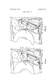
- FIG. 1 is'a schematic plansketch of a film cassette in accordance with ourinvention, withparts shown in cross section and parts broken away;
- FIG. 2 is a schematic plan view, with parts broken away, of a strip of photographic film useful in the eastaining its own film processing system, while reducing the energy requirements on the processing system and thereby making it possible to utilize a more compact and lighter weight construction than was formerly deemed practical.
- Such a cassette comprises an external housing of opaque material, formed with a film gate. Takeup and supply reels are 'rotatably mounted in the housing, and adapted for connection to external drive means. A supply of strip film is connected at its ends to the reels, and passes therebetween through the film gate for cooperation with a camera and projector.
- the film is provided with sprocket holes, so that the portion exposed through the film gate can be engaged by the film advance pawl of either a camera or a projector, for incremental advance of the film.
- FIG. 3 is a fragmentary schematic perspective sketch of a detail of the apparatus of FIG. 1, showing the relationship of a film engaging hook to a fragment of the film of FIG. 2;
- FIG. 4 is a schematic elevational sketch of the hook shown in FIG. 3, taken substantially along the lines 4-4 in FIG. 3;
- FIG. 5 is a fragmentary schematic plan sketch, with parts omitted, parts shown in cross section, and parts broken away, of a portion of the apparatus of FIG. 1, showing the parts in a second position .assumed during the sequence of operation of the processing system of FIG. 1;
- FIGS. 6 and 7 are fragmentary schematic plan sketches, with parts omitted, parts shown in cross section, and parts broken away, of the apparatus of FIG. 1, showing the parts in still other positions assumed during the sequence of operation of the processing system of our invention;
- FIG. 8 is a schematic plan sketch, with parts omitted, parts shown in cross section, and parts broken away, of a modified photographic cassette in accordance with a second embodiment of our invention.
- FIG. 8a is a fragmentary perspective sketch of a portion of the apparatus of FIG. 8;
- FIG. 8b is a fragmentary perspective sketch of another portion of the apparatus of FIG. 8;
- FIGS. 9-13 comprise fragmentary plan sketches, with parts omitted, parts shown in cross section, and parts broken away, illustrating the operation of the apparatus of FIG. 8 as it proceeds through a film processing cycle in accordance with our invention
- FIG. 14 is a schematic perspective sketch of a pressure pad forming a part of the processing apparatus of FIGS. 8-13;
- FIG. 15 is a fragmentary schematic perspective sketch of a detachable hook forming a part of the apparatus of FIGS. 8-13, shown in combination with the support with which it is initially engaged;
- FIG. 16 is a fragmentary schematic plan sketch of portions of the apparatus of FIGS. 14 and 15, taken substantially along the lines 16-16 in FIG. 14;
- FIG. 17 is a fragmentary schematic plan sketch, on an enlarged scale, illustrating a modification of the apparatus of FIGS. 8-16, incorporating a shutoff nozzle for the coating apparatus;
- FIG. 18 is a schematic end view, with parts omitted, parts shown in cross section, and parts broken away, taken substantially along the lines 1818 in FIG. 17;
- FIG. 19 is a fragmentary schematic plan view of a portion of the apparatus of FIG. 17, taken substantially along the lines 19-19 in FIG. 17;
- FIG. 20 comprises a fragmentary schematic plan sketch, with parts omitted, parts shown in cross section, and parts broken away, of still another embodiment of the cassette of our invention.
- FIG. 20a is a fragmentary perspective sketch of a I portion of the apparatus of FIG. 20;
- FIG. 24 is a schematic perspective sketch illustrating the relationship between the cassette (corresponding to any of the embodiments shown in FIGS. l-22) in its operative association with a film drive and projection system and a viewing screen;
- FIG. 25 is a schematic block and wiring diagram illustrating the manner in which the film drive and projection apparatus of FIGS. 23 and 24 may be operated to manipulate the cassette of any of FIGS. l-22 to cause the processing and projection operations to be described to be carried out in accordance with our invention
- FIG. 26 is a fragmentary plan sketch, with parts omitted, parts broken away and parts shown in block diagram form, illustrating another modification of the eassette of our invention.
- a film cassette generally designated 1 and comprising. a base member generally designated 2 of any suitable material such as metal, opaque plastic, or the like.
- the base member 2 is provided with side walls 3 substantially circumscribing the cassette, except for a film gate, to be described.
- the side walls 3 are formed integral with a base plate 4, fragmentarily shown in FIG. 1, that completes one side of the housing.
- the housing is completed by a cover, generally designated and fragmentarily shown in FIG. 1, of metal, opaque plastic, or the like.
- the cover 5 is provided with a top portion 6, forming a side of the cassette opposite the base plate 4, and formed integral with side walls 7 that are interfitted with the side walls 3 of the base 2 in any conventional manner, not shown in detail, such that when assembled together, the base 2 and cover 5 form a light-tight housing that is pierced in a manner to be described by lightbaffled apertures forming a film gate.
- the base and cover parts 2 and 5 may be interlocked by cooperating detents formed in the parts in a conventional manner. If of plastic, the parts may simply be adapted to fit relatively closely together, and there sealed into integral relationship during final assembly of the appparatus.
- the factor governing the location of the parting lines between the base and cover is simply manufacturing convenience. Specifically, it is convenient to take one portion, here shown as the base 2, as a platform upon which all of the additional fixed and moving parts to be described can be assembled in their initial operating relationship before the cover 5 is mounted on the base and there secured.
- a supply reel generally designated 8 having a spool portion schematically shown at 9, and a takeup reel generally designated 10, having a spool portion schematically illustrated at 11.
- a strip of film 12 whose construction will be described in more detail below, has one end connected to the supply reel 8 and an opposite end connected to the takeup reel 10.
- the film 12 is initially in its unexposed state, and is coiled'primarily about the supply reel 8. In FIG. 1, however, it is shown coiled primarily about the takeup reel 10, as it would generally appear after exposure of the film in a camera.
- the film 12 extends from the supply reel 8 over a path along which it first encounters a conventional bobulator roll 13.
- the film engages a portion of the periphery of the bobulator roll, as shown, and passes therefrom around a conventional idler roll 14 journalled for rotation in the housing, and thence through a conventional light-baffled aperture schematically indicated at 15 and forming a portion of a film gate in the housing.
- the film l2 re-enters the housing through a second light-baffled aperture generally designated 16 and comprising a second portion of the film gate.
- the film 12 next passes over a conventional snubber roll generally designated 17, and thence to the takeup reel 10.
- the bobulator 13 may be of any conventional construction, and performs the known function of isolating the film drive pawl associated with the camera or viewing apparatus, to be described, from the inertia of the supply reel 8.
- the bobulator roll 19 is mounted in any conventional manner on a pivot that is in turn mounted on a support movable with respect to the frame and biased by a spring, such that the bobulator roll can be moved backwards and forwards in the directions of the double arrow shown in FIG. 1.
- the bobulator roll thus responds to increases or decreases in the tension of the film 12 by temporarily shortening or lengthening the film path, respectively.
- Such changes in film tension are produced by the actuation of the film drive pawl, and determined by the inertia forces exerted by the supply reel 8, together with the larger or smaller supply of film that may be on it at any given time.
- a light-tight sheild around the film gate formed by the apertures 15 and 16 is formed by a wall portion 18 formed integrally with the base plate 4 of the base 2 and later formed integral with the cover 5 in the manner described above. An exposed chamber behind the film is thus formed for the purpose of admitting projection light.
- the apparatus for this purpose is conventional, and will only briefly be described.
- it comprises a prism generally designated 19 and comprising a mirror, not shown in FIG. 1 but to be described in more detail in connection with FIG. 23, to direct light, entering the cassette through an effective aperture schematically indicated at 20 and normal to the plane of FIG. 1, downwardly through the film 12 in the film gate in FIG. 1 for projection through a suitable lens assembly, to be described.
- a conventional pressure plate located between the prism and the film, and spring biased into engagement with the film.
- the pressure plate serves in the conventional manner to cooperate with a camera, by locating the focal plane of the film during exposure.
- a conventional framing aperture is also provided in the pressure plate, now shown, to pass light entering through the prism assembly 19 through a selected frame of the film 12, after the film is processed in a manner to be described.
- the snubber roll 17 may also be of entirely conventional construction. As illustrated, it is provided with a hub portion schematically indicated at 21 that is adapted to protrude through a suitable light-baffled aperture in the cover panel 6 for engagement by a stop member, comprising a part of either the camera or the projection system that is engaged when the film is to be incrementally advanced by a pawl for exposure or projection purposes.
- a stop member comprising a part of either the camera or the projection system that is engaged when the film is to be incrementally advanced by a pawl for exposure or projection purposes.
- The'takeup reel 8 and the supply reel 10 are provided with drive sprockets 22 and 23, respectively, which in the embodiment here shown and described are adapted to protrude from the cover panel 6, through suitable light-baffled apertures, for engagement with corresponding drive sprockets comprising a part of a camera, or of the projection apparatus.
- drive sprockets 22 and 23 are adapted to protrude from the cover panel 6, through suitable light-baffled apertures, for engagement with corresponding drive sprockets comprising a part of a camera, or of the projection apparatus.
- the projection apparatus 'both supply and takeup reels are adapted to be driven through slip clutches.
- the camera only a drive for the takeup reel need be provided.
- This drive comprises a slip clutch connected to a sprocket driving the takeup reel drive sprocket 23, in cooperation with a film drive pawl sequentially engaging a series of sprockets formed on the film 12, in an array to be described, along a portion of the edge of the film in the filmgate between the apertures and-l6.
- the snubber reel 17 is engaged only while the film is to be incrementally advanced onto the takeup reel.
- the snubber reel 17 is disengaged and acts as an idler. As will appear, that may occur prior to processing, during processing of the film while rewinding, or during subsequent rewinding of the processed film after projection.
- the film 12 In its path between the bobulator roll 13 and the film 'gate aperture 15, the film 12 passes over a path seg- Referringto FIG. 2, the film 12 is shown to comprise a leader terminating in an end formed with an aperture such as 24.
- the aperture 24 serves to connect that end of the film to the takeup reel 10.
- Behind the leader which may be in the neighborhood of 18 inches in length, there is a strip of photographically useful film, upon which projectable images may be formed, and which may be, for example, approximately 52 feet in length for 8 mm film.
- a trailer region terminating at another end in an aperture 25 by means of which that end .of the film is adapted to be connected to the supply reel 8.
- the film 12 may comprise a base of any suitable transparent material of the kind conventionally used for film bases. On this base is applied, at least over the central portion of the photographically useable length of the film, an emulsion comprising a photosensitive coating, whereon a series of latent images illustrated by an initial frame 1 and a terminating end frame in FIG. 2 may be formed with a camera.
- Photosensitive coatings useable in the practice of our invention may be of any conventional variety adapted to be developed by a monobath processing composition to form a positive transparency suitable for projection.
- a currently preferred embodiment of our invention makes use of a film structure which, upon the base, comprises a photosensitive layer including both a photosensitive negative emulsion and an imagereceiving layer to which a positive image may be transferred by diffusion during development without necessitating the subsequent removal of the emulsion containing its developed negative image.
- This highly desirable feature is made possible by a developed negative image having low covering power.
- a silver halide developer and a silver halide solvent are applied in an aqueous alkaline solution to a photoexposed silver halide stratum or emulsion, where they develop exposed silver halide to silver, and react with unreduced silver halide to form a soluble silver complex.
- This complex in order to form a positive print, is transferred and reduced to silver on a silver-receptive stratum upon which the silver halide stratum has been superposed.
- the silver-receptive and silver halide strata have been separated in order to render the positive print visible.
- the positive print may be rendered visible without separation of the silver halide and silver-receptive strata.
- the silverreceptive stratum may be so constituted as to provide an unusually vigorous silver precipitating environment which causes the silver deposited upon it, in comparison with silver developed in the silver halide stratum, to possess very high covering power, i.e., opacity for a given mass of reduced silver. If the silver halide is in such a concentration as to give rise only when fully developed to a predetermined low maximum density, and if the silver complex is reduced to silver in a vigorous silver precipitating environment, the resulting negative and positive prints in superposition provide a composite print that presents a good image for projection purposes so long as they are contained on a transparent support. Since the silver halide stratum and the silver receptive stratum need not be separated, an overall simplification of the silver transfer-reversal process is achieved.
- a composite film assembly of this type, as well as processing compositions for producing a fully developed black and white image .without the necessity of removing the developed negative image after processing, are shown in prior U.S. Pat. No. 2,861,885 to Edwin H. Land, which issued on Nov. 25, 1958 for Photographic Processes and'Products.
- Other composite film assemblies capable of producing developed full color images without the necessity of removing the developed emulsion are shown in prior U.S. Pats. of Edwin H. Land, Nos. 2,726,154, issued Dec. 6, 1955, for Photographic Products, and 2,944,894, issued July 12, 1960, for Photographic Processes Utilizing Screen Members.
- our invention is not directed to the chemistry by which images are developed in a photosensitive emulsion and transferred to an image receiving strata.
- the film employed is black and white or color film
- the preferred embodiment of our invention employs film of a type not requiring the removal of a negative emulsion after it is developed.
- the film 12 is formed along one edge with sprocket holes such as 26 at regular intervals adapted to cooperate with a drive pawl in either camera or projector for incremental advancement of the film in the manner discussed above.
- the series of sprocket holes adjacent the trailing end of the film may be interrupted by an elongated sprocket hole 27.
- Such a hole which may span, for example, two of the normally spaced sprocket holes 26, will pass the camera pawl without film advance, and thus terminate advance of the film in the camera at a predetermined exposure end point so selected that the film will not be carried substantially beyond the usable emulsion portion.
- a similar pawl in the film drive and projection apparatus to be described may also be used to terminate forward movement in the projector.
- the film drive and projector unit may be provided with a double pawl to pass this first elongated aperture 27, and advance movement in that apparatus may be terminated by a further elongated sprocket hole, not shown.
- a single pawl in the projector may be employed, but the snubber roll can be disconnected prior to processing to allow the film to be carried forward onto the takeup reel until advance motion is terminated by slipping of the drive clutch as the end of the trailer on the supply reel is reached.
- the latter mode of film advance termination is preferred.
- a central aperture 28 adapted to engage the processing apparatus in a manner to be described to commence the processing operation. Adjacent the aperture 28 is formed an edge notch 29 which functions in a manner to be described below. Similarly, adjacent the leading end of the film 12 is formed, in the region generally designated by the arrows B, a central aperture 30 and an adjacent edge notch 31. These latter singularities in the film cooperate with the processing apparatus in a manner to be described to terminate film processing and disengage the processor.
- the processing apparatus of our invention is shown as comprising a reverse roll coater generally designated 32.
- the coater 32 comprises an outer housing 33 journaled to the base plate 4 for rotation in the housing by means shown here as a pivot post 34 formed integral with the wall 4.
- the housing 33 is thus adapted to rotate in the cassette housing between an inactive position, shown in FIG. 1,
- a coating roll 36 engages the film 12, and is also drivingly engaged with the idler 14, in a manner to appear, so as to rotate in a direction opposite to the rotation of the idler 14 and against movement of the film 12 as it is advanced from the takeup reel towards the supply reel during processing.
- the coating roll 36 is journalled in the housing 33 by means here schematically shown as a shaft '37.
- -A recess 38 is formed in the housing to receive the roll 36, and communicates with a passage 39 in the housing 33.
- a wick 40 of any suitable capillary material, adapted to absorb processing composition supplied to it in a manner to be described and apply the composition to the roll 36 during processing.
- the lower end of the wick 40 communicates with an enlarged chamber 41 formed in the housing 33 below an initially sealed pod 42, containing processing composition of the kind described above.
- the pod 42 may be made of any suitable material, such as lead foil or the like, coated atleast internally with a suitable material, such as a conventional synthetic thermoplastic resin or the like, chosen to be resistant to the processing composition.
- the pod may be retained in the position shown by friction, suitable retaining ledges, or by any conventional adhesive or the like.
- the pod 42 is adapted to be opened in a manner to be described to release processing composition to the wick 40, and thereby supply the roll 36.
- a knife blade generally designated 43 is slidably mounted adjacent the lower end of the .pod 42 and provided with a cutting edge 44 tapering to a sharp corner 45.
- the blade 43 is slidably mounted in the housing 33, and guided by guides schematically indicated at 46 connected to or formed integral with the housing 33.
- One end of the knife blade 43 is connected, in a manner sufficiently suggested but not shown in FIG. 1, to a cable 47, of steel wire or cable, a synthetic resin monofilament, or the like.
- the cable 47 extends through a suitable aperture in a guide and stop member 48 formed integral with the housing 33, and thence through a suitable aperture 49 formed in the housing 33, about an idler 50 journalled to or formed integral with the base plate 44, to an end 51 connected to a lever 52, to be described.
- a stop 53 is secured to the cable 47, and is adapted to engage the stop and guide member 48 to limit the movement of the cable 47, for purposes to appear in detail below. Generally, however, it will be apparent that as the cable 47 is drawn upwardly and to the right in FIG. 1, the blade 43 will engage the pod 42, cutting it open and releasing the processing composition. Other functions accomplished by movement of the cable-47 will be apparent as the description proceeds.
- the processor housing 33 is urged upwardly against a stop 35 formed integrally with the base plate 4 by means comprising a compressed spring 54.
- the spring 54 extends between the base of the housing 33 and a wall portion 55, formed integrally with the wall portion 18 and the base plate 4, and ultimately secured to the cover plate 6.
- a latch member 56 is formed integral with or otherwise secured to the housing 33, and is at times adapted to cooperate with a detachable hook 57 frictionally engaged in a slot formed in a wall member 58 formed integral with the floor plate 4.
- the latch elements comprising the member 56 and the shank 59 of the hook 57 are shown disengaged in the initial position of the apparatus illustrated in F IG. 1, and in their engaged position in FIG. 6, to be described.
- a lever '52 is pivoted to a suitable post 60 formed integral with the floor plate 4 by conventional means here shown as a pivot pin 61.
- the lever 52 is initially engaged with a stop post 62 formed integral with the floor'plate 4, as by a very light force exerted on the cable 47 by friction through its guides, and by slight frictional engagement of the blade 43 with its guides 46. Since the lever 52 and its attachments may be of very light construction, no great force is required to keep the lever in this initial position.
- the lever 52 is formed with an end 63 that is adapted to engage a detent generallydesignated 64.
- the detent '64 comprises a spring 65 formed with locating projections 66 adapted to engage a cooperating recess 66a in the lever 52.
- the spring 65 is mounted on the base plate 4 by suitable fastening means schematically shown at 67.
- the lever 52 engages the detent assembly 64, in the manner illustrated in FIG. 5, at times to be described.
- the lever 52 is formed at its end 63 with-a slot 68 adapted to frictionally receive a detachable hook generally designated '69.
- the hook 69 is adapted to engage an aperture in the film 12.
- the hooks 57 and 69 are each adapted for unidirectional engagement with a different one of the film apertures and 28, respectively.
- the hook 69 is adapted to ride over an aperture in the film such as 28 when the film is moved towards the takeup reel from the supply reel, butto engage such an aperture if it passes the hook 69 as the film is moved towards the supply reel.
- the hook 5 7 is adapted to engage an aperture such as 30 when the film is moved towards the supply reel, and to ride over such an aperture as the film moves towards the takeup reel.
- both the hooks 69 and 57 are adapted to pass over the emulsion side of the film while they are in position and before they are engaged and detached. It is desirable for these hooks to exert their forces in response to forces applied from the center of the film strip, but quite undesirable that the hooks pass over the emulsion even though they do not engage it with any appreciable force. Thus, it is preferred to form the hooks in the manner shown in FIGS.
- FIGS. 3 and 4 will be described in their application to the hook 69, but it should be apparent to those skilled in the art that the hook 57 may be of identical construction and cooperate with the film in the same manner.
- the hook generally designated 69 is adapted to cooperate with the central recess 28 inthe film 12, and with the corresponding associated side notch 29.
- a side rider 70' is formed on the hook that is adapted to engage the edge of the film opposite the sprocket holes 26 and cause the effective hook portion 71 of the hook 69 to be held up away from the emulsion until the side notch 29 is reached, at which point the portion 70 drops into the side notch and allows the hook portion 71 to enter and engage the end of the notch 28.
- the shank portion 72 of thehook 69 is adapted to be frictionally engaged by the slot in the-end portion 68 of the lever 52, as described above.
- the cassette is initially manufactured and supplied to the user with the film unexposed and disposed primarily on the supply reel 8.
- the film is exposed by the user by placing the cassette in a suitable camera, which advances it incrementally onto the takeup spool reel 10, 'while exposing successive frames of the usable portion of the film between the intervals of film advancement.
- the film When the film is exposed in the camera, it is primarily stored on the takeup reel, as shown in FIG. 1. Either during this advancement of the film in the camera, or following a subsequent advance towards the takeup reel that may be carried out by appropriate actuation of the film drive and projection apparatus to be briefly described below, the location A of the film aperture 28 and its corresponding side notch 29 is advanced to the position shown in FIG. 1, beyond the hook 69 in the direction of the takeup reel. That operation readies the film for processing upon first rewinding onto the supply reel, in a manner next to be described.
- the cable 47 is drawn up to bring the blade 43 into cutting engagement with the pod 42, cutting open the pod and releasing processing composition, generally designated 73.
- the composition 73 then flows down into the reservoir chamber 41, to be absorbed by the wick 40, and thus applied to the coating roll 36.
- the hook 69 continues to move the lever 52, beyond the detented position shown in FIG. 5, to a position shown in FIG. 6. In this position, the force on the hook 69 becomes sufficient to detach the hook from the lever S2.
- the lever 52 Prior to detachment of the hook 69, the lever 52 carries the cable 47 generally upwards in FIG. 6. As shown in FIG. 5, at approximately the detented position established by the detent assembly 64, the stop 53 on the cable 47 engages the stop and guide assembly 48. Thereafter, movement of the cable 47 causes a movement of the processor toward the idler 50 that ultimately results in engagement of the coating roll 36 with the film 12. At the same time, sprockets 74 attached to or formed integral with the coating roll 36 engage corresponding sprockets 75 formed integral with or attached to the idler 14, and begin to drive the coating roll 36 oppositely to the direction of motion of the film 12. When the processor is thus engaged with the film and with the drive sprockets on the idler, the latch member 56 engages the shank 59 of the hook 57 to hold the processor in its film engaging position.
- Processing of the film 12 will continue with the apparatus in the position shown in FIG. 6 as the film is advanced onto the takeup reel, with the processing composition 73 being'gradually exhausted as suggested in FIG. 6.
- the amount of the composition 73 is selected so that the composition will be substantially exhausted as the end of the photographically usably portion of the film is reached and passed.
- the location B of the film aperture 30 and its associated side notch 31 approaches and reaches the location of the hook 57.
- the bight of the book 57 will then enter the central aperture 30 and be moved with the film 12 toward the supply reel 8
- the force of the film 12 reaches a sufficient level to overcome the frictional forces exerted by the slot in the support 58 and by the engaging latch member 56
- the shank of the hook will be detached from the support 58. That will release the latch 56 and allow the processor housing 33 to be moved upwards about its pivot 34, under the influence of the spring 54, until it again engages the stop 35.
- the hooks 57 and 69 may remain with the film, being made for that purpose of light metal or plastic.
- the hooks may be made of light ferromagnetic material adapted to be attracted to and thereafter retained by a magnet such as 76, suggested in FIGS. 1, 5 and 6, affixed to the housing, as by securing it to the floor plate 4.
- the film be projected, and thereby intermittently advanced from the supply reel onto the takeup reel 10, and thereafter rewound onto the supply reel 8. This operation not only permits the operator to immediately review the results of his photography, but serves to further aid in completely drying the processed film.
- FIGS. 8-16 show another embodiment of our invention in which a drag coater, and specifically, a doctor bar coater, is employed as the processing means.
- a drag coater and specifically, a doctor bar coater
- Such a coater is generally to be preferred because it is inherently relatively insensitive to changes in viscosity of the processing composition, as a function of temperature or formulation, as well as to reasonable changes in processing speed of the film as it is moved past the processing station. That is, the doctor bar will inherently lay down a coating approximately one-half the thickness of the aperture between the bar and the coated substrate over a relatively wide range of processing conditions.
- doctor bar coater This property of the doctor bar coater is well known in the art per se, but we have discovered that it is especially desirable for use in self-contained processing systems for film and the like, because otherwise onerous requirements on the processing system are thereby greatly relaxed.
- the processing composition will be exposed to considerable variations in temperature, and may be applied to the film while its temperature is changing.
- black and white or color emulsions of different speed and processing characteristics may require different formulations of processing compositions involving varying viscosity.
- the cassette in 'accor dance with this embodiment of our invention comprises 7
Landscapes
- Physics & Mathematics (AREA)
- General Physics & Mathematics (AREA)
- Photographic Developing Apparatuses (AREA)
- Replacement Of Web Rolls (AREA)
Priority Applications (6)
| Application Number | Priority Date | Filing Date | Title |
|---|---|---|---|
| US00227170A US3806245A (en) | 1972-02-17 | 1972-02-17 | Photographic film cassette comprising internally programmed self-contained film processing system |
| CA161,661A CA1001468A (en) | 1972-02-17 | 1973-01-19 | Photographic film cassette containing internally programmed self-contained film processing system |
| DE2306989A DE2306989C2 (de) | 1972-02-17 | 1973-02-13 | Selbstentwicklerfilmkassette |
| GB730573A GB1377033A (en) | 1972-02-17 | 1973-02-14 | Motion-picture film cassettes |
| JP1886473A JPS5611943B2 (OSRAM) | 1972-02-17 | 1973-02-15 | |
| FR7305580A FR2182851B1 (OSRAM) | 1972-02-17 | 1973-02-16 |
Applications Claiming Priority (1)
| Application Number | Priority Date | Filing Date | Title |
|---|---|---|---|
| US00227170A US3806245A (en) | 1972-02-17 | 1972-02-17 | Photographic film cassette comprising internally programmed self-contained film processing system |
Publications (1)
| Publication Number | Publication Date |
|---|---|
| US3806245A true US3806245A (en) | 1974-04-23 |
Family
ID=22852045
Family Applications (1)
| Application Number | Title | Priority Date | Filing Date |
|---|---|---|---|
| US00227170A Expired - Lifetime US3806245A (en) | 1972-02-17 | 1972-02-17 | Photographic film cassette comprising internally programmed self-contained film processing system |
Country Status (6)
| Country | Link |
|---|---|
| US (1) | US3806245A (OSRAM) |
| JP (1) | JPS5611943B2 (OSRAM) |
| CA (1) | CA1001468A (OSRAM) |
| DE (1) | DE2306989C2 (OSRAM) |
| FR (1) | FR2182851B1 (OSRAM) |
| GB (1) | GB1377033A (OSRAM) |
Cited By (7)
| Publication number | Priority date | Publication date | Assignee | Title |
|---|---|---|---|---|
| US3895862A (en) * | 1973-12-26 | 1975-07-22 | Polaroid Corp | Processing fluid release device and method for multipurpose film cassettes |
| US3923520A (en) * | 1974-07-26 | 1975-12-02 | Polaroid Corp | Film strip cassette with moving processing fluid doctoring surface |
| US4203655A (en) * | 1979-01-02 | 1980-05-20 | Polaroid Corporation | Tapered pressure pad to prevent film scratching |
| US4209235A (en) * | 1979-05-04 | 1980-06-24 | Polaroid Corporation | Film cassette processor having capillary grooves |
| US4248507A (en) * | 1979-12-31 | 1981-02-03 | Polaroid Corporation | Multipurpose photographic film handling cassette having an improved film processor arrangement |
| US4285581A (en) * | 1979-12-31 | 1981-08-25 | Polaroid Corporation | Multipurpose film handling cassette having a modular film processor |
| US4314744A (en) * | 1980-08-22 | 1982-02-09 | Polaroid Corporation | Multipurpose film handling cassette having preliminary assembly condition |
Citations (8)
| Publication number | Priority date | Publication date | Assignee | Title |
|---|---|---|---|---|
| US2435718A (en) * | 1946-01-11 | 1948-02-10 | Polaroid Corp | Photographic process and apparatus for subjecting a photographic film to a processing fluid |
| US2520641A (en) * | 1947-12-09 | 1950-08-29 | Polaroid Corp | Photographic apparatus |
| US2558858A (en) * | 1948-02-03 | 1951-07-03 | Polaroid Corp | Photographic apparatus |
| US2966103A (en) * | 1958-10-21 | 1960-12-27 | Polaroid Corp | Photographic apparatus for treating photosensitive material |
| US3608455A (en) * | 1969-04-04 | 1971-09-28 | Polaroid Corp | System for processing a strip of photographic material |
| US3623417A (en) * | 1968-11-01 | 1971-11-30 | Polaroid Corp | System for uniformly coating exposed motion picture film with processing fluid |
| US3641896A (en) * | 1969-04-04 | 1972-02-15 | Polaroid Corp | Motion picture film cassette-processor system |
| US3667361A (en) * | 1969-01-08 | 1972-06-06 | Mattel Inc | Film developing camera |
Family Cites Families (2)
| Publication number | Priority date | Publication date | Assignee | Title |
|---|---|---|---|---|
| DE1156639B (de) * | 1961-02-01 | 1963-10-31 | Zeiss Ikon Ag | Photographische Rollfilmkamera mit elektromotorischem Antrieb des Filmtransports |
| US3616740A (en) * | 1969-01-13 | 1971-11-02 | Polaroid Corp | System and method for processing a strip of exposed photographic material |
-
1972
- 1972-02-17 US US00227170A patent/US3806245A/en not_active Expired - Lifetime
-
1973
- 1973-01-19 CA CA161,661A patent/CA1001468A/en not_active Expired
- 1973-02-13 DE DE2306989A patent/DE2306989C2/de not_active Expired
- 1973-02-14 GB GB730573A patent/GB1377033A/en not_active Expired
- 1973-02-15 JP JP1886473A patent/JPS5611943B2/ja not_active Expired
- 1973-02-16 FR FR7305580A patent/FR2182851B1/fr not_active Expired
Patent Citations (8)
| Publication number | Priority date | Publication date | Assignee | Title |
|---|---|---|---|---|
| US2435718A (en) * | 1946-01-11 | 1948-02-10 | Polaroid Corp | Photographic process and apparatus for subjecting a photographic film to a processing fluid |
| US2520641A (en) * | 1947-12-09 | 1950-08-29 | Polaroid Corp | Photographic apparatus |
| US2558858A (en) * | 1948-02-03 | 1951-07-03 | Polaroid Corp | Photographic apparatus |
| US2966103A (en) * | 1958-10-21 | 1960-12-27 | Polaroid Corp | Photographic apparatus for treating photosensitive material |
| US3623417A (en) * | 1968-11-01 | 1971-11-30 | Polaroid Corp | System for uniformly coating exposed motion picture film with processing fluid |
| US3667361A (en) * | 1969-01-08 | 1972-06-06 | Mattel Inc | Film developing camera |
| US3608455A (en) * | 1969-04-04 | 1971-09-28 | Polaroid Corp | System for processing a strip of photographic material |
| US3641896A (en) * | 1969-04-04 | 1972-02-15 | Polaroid Corp | Motion picture film cassette-processor system |
Cited By (7)
| Publication number | Priority date | Publication date | Assignee | Title |
|---|---|---|---|---|
| US3895862A (en) * | 1973-12-26 | 1975-07-22 | Polaroid Corp | Processing fluid release device and method for multipurpose film cassettes |
| US3923520A (en) * | 1974-07-26 | 1975-12-02 | Polaroid Corp | Film strip cassette with moving processing fluid doctoring surface |
| US4203655A (en) * | 1979-01-02 | 1980-05-20 | Polaroid Corporation | Tapered pressure pad to prevent film scratching |
| US4209235A (en) * | 1979-05-04 | 1980-06-24 | Polaroid Corporation | Film cassette processor having capillary grooves |
| US4248507A (en) * | 1979-12-31 | 1981-02-03 | Polaroid Corporation | Multipurpose photographic film handling cassette having an improved film processor arrangement |
| US4285581A (en) * | 1979-12-31 | 1981-08-25 | Polaroid Corporation | Multipurpose film handling cassette having a modular film processor |
| US4314744A (en) * | 1980-08-22 | 1982-02-09 | Polaroid Corporation | Multipurpose film handling cassette having preliminary assembly condition |
Also Published As
| Publication number | Publication date |
|---|---|
| DE2306989C2 (de) | 1982-05-13 |
| FR2182851B1 (OSRAM) | 1983-04-08 |
| GB1377033A (en) | 1974-12-11 |
| JPS5611943B2 (OSRAM) | 1981-03-18 |
| DE2306989A1 (de) | 1973-08-23 |
| FR2182851A1 (OSRAM) | 1973-12-14 |
| CA1001468A (en) | 1976-12-14 |
| JPS4895229A (OSRAM) | 1973-12-06 |
Similar Documents
| Publication | Publication Date | Title |
|---|---|---|
| US4488796A (en) | Photographic still camera film system | |
| US3641896A (en) | Motion picture film cassette-processor system | |
| EP0494680B1 (en) | A photographic camera | |
| US3623417A (en) | System for uniformly coating exposed motion picture film with processing fluid | |
| US3806245A (en) | Photographic film cassette comprising internally programmed self-contained film processing system | |
| US3800306A (en) | Method of operating a film handling cassette | |
| US3895862A (en) | Processing fluid release device and method for multipurpose film cassettes | |
| US3648584A (en) | Photographic film handling and processing system | |
| US2966103A (en) | Photographic apparatus for treating photosensitive material | |
| US3807840A (en) | Film handling cassette having reel locking means | |
| US3768894A (en) | Photographic cassette containing film strip programmed for manual and automatic operation and film processor therefor | |
| JPH0377983B2 (OSRAM) | ||
| US3608455A (en) | System for processing a strip of photographic material | |
| US3643579A (en) | Motion picture processing system | |
| US3809465A (en) | Motion picture system | |
| US3902797A (en) | Film guided playback and recording mechanism | |
| US3767297A (en) | Motion picture processing and projection system employing multi-purpose cassette | |
| US3893756A (en) | Sound motion picture processing and projection system | |
| US4531684A (en) | Apparatus having improved film take-up spool | |
| US3249434A (en) | Process for recovering processed photographic sheet material | |
| US3905690A (en) | Film guided playback and recording mechanism | |
| US4212521A (en) | Motion picture film cassette having removable film stripping web | |
| US3809327A (en) | Film transport system for photographic cassette having self-contained film processing system | |
| US3537784A (en) | Motion picture processing and projection system employing multipurpose cassette and strip tape | |
| US3999844A (en) | Photographic system |