US3800549A - Tunnelling apparatus - Google Patents
Tunnelling apparatus Download PDFInfo
- Publication number
- US3800549A US3800549A US00283898A US3800549DA US3800549A US 3800549 A US3800549 A US 3800549A US 00283898 A US00283898 A US 00283898A US 3800549D A US3800549D A US 3800549DA US 3800549 A US3800549 A US 3800549A
- Authority
- US
- United States
- Prior art keywords
- members
- wall
- wall components
- wall component
- units
- Prior art date
- Legal status (The legal status is an assumption and is not a legal conclusion. Google has not performed a legal analysis and makes no representation as to the accuracy of the status listed.)
- Expired - Lifetime
Links
- 238000000034 method Methods 0.000 description 3
- ATJFFYVFTNAWJD-UHFFFAOYSA-N Tin Chemical compound [Sn] ATJFFYVFTNAWJD-UHFFFAOYSA-N 0.000 description 1
- 230000000295 complement effect Effects 0.000 description 1
- 230000000694 effects Effects 0.000 description 1
- 230000000149 penetrating effect Effects 0.000 description 1
- 229910052718 tin Inorganic materials 0.000 description 1
Images

Classifications
-
- E—FIXED CONSTRUCTIONS
- E21—EARTH OR ROCK DRILLING; MINING
- E21D—SHAFTS; TUNNELS; GALLERIES; LARGE UNDERGROUND CHAMBERS
- E21D9/00—Tunnels or galleries, with or without linings; Methods or apparatus for making thereof; Layout of tunnels or galleries
- E21D9/06—Making by using a driving shield, i.e. advanced by pushing means bearing against the already placed lining
- E21D9/0692—Cutter drive shields
-
- E—FIXED CONSTRUCTIONS
- E21—EARTH OR ROCK DRILLING; MINING
- E21D—SHAFTS; TUNNELS; GALLERIES; LARGE UNDERGROUND CHAMBERS
- E21D9/00—Tunnels or galleries, with or without linings; Methods or apparatus for making thereof; Layout of tunnels or galleries
- E21D9/06—Making by using a driving shield, i.e. advanced by pushing means bearing against the already placed lining
- E21D9/08—Making by using a driving shield, i.e. advanced by pushing means bearing against the already placed lining with additional boring or cutting means other than the conventional cutting edge of the shield
- E21D9/0875—Making by using a driving shield, i.e. advanced by pushing means bearing against the already placed lining with additional boring or cutting means other than the conventional cutting edge of the shield with a movable support arm carrying cutting tools for attacking the front face, e.g. a bucket
- E21D9/0879—Making by using a driving shield, i.e. advanced by pushing means bearing against the already placed lining with additional boring or cutting means other than the conventional cutting edge of the shield with a movable support arm carrying cutting tools for attacking the front face, e.g. a bucket the shield being provided with devices for lining the tunnel, e.g. shuttering
Definitions
- ABSTRACT A tunnelling apparatus composed of a plurality of elongate planks arranged sidc-by-side on a circumferential path to form a shield of circular configuration.
- planks are separated into two relatively movable groups with the individual members alternately staggered so that a member of one group is disposed between two members of another group.
- Each group of planks is supported on three axially spaced expandible 14 Claims, 4 Drawing Figures PATENIEDAPR 2 I914 SHEET 1 [IF 2 BACKGROUND OF THE INVENTION
- the present invention relates to an apparatus for use in driving underground tunnels and to a method of driving tunnels using such an apparatus.
- a general object of this invention is to provide an improved apparatus for, and method of, driving tunnels.
- an apparatus for use in driving underground tunnels including a shield wall with relatively movable components, each component being composed of a plurality of substantially parallel elongate members, wherein the elongate members of one wall component are interspersed with the elongate members of the other wall component and the elongate members of each wall component are supported by at least one device adapted to brace said members against the wall of a tunnel.
- a method of driving a tunnel comprising bracing a plurality of elongate members forming a rear shield wall component against the surface of the tunnel, advancing a further plurality of elongate members forming a complementary forward shield wall component longitudinally outwardly of said braced wall component, advancing a cutting appliance longitudinally outwardly from said further plurality of members to remove material from a face, bracing said further plurality of members against the surface of the tunnel, relieving said first-mentioned plurality of members from the surface of the tunnel drawing up the first-mentioned plurality of members between the further plurality of members and re-bracing said first-mentioned plurality of members against the surface of the tunnel.
- the elongate members of the wall components are arranged to lie on a common circumferential path with each of at least some of the elongate members of one of the wall components being disposed between two of the elongate members of the other wall component.
- the members are thus alternately staggered in the circumferential direction and small gaps may be left between the sides of the individual members.
- the wall components can be alternately advanced, while providing an adequate continuous shield, with each component being alternately braced against the tunnel wall to form a thrust abutment for the advance of the other component.
- the outer faces of the elongate members of one of the wall components may be disposed outwardly relative to the outer faces of the elongate members of the other forward wall components. This one component can then form the rear support of the shield which is alternately braced and moved up to the wall component forming the front support.
- each support device may take the form of two half-rings interconnected by piston and cylinder units, operable to move the half-rings together or apart to thereby contract or expand the device to relieve or brace the members of the associated wall component.
- the devices may conveniently be arranged in pairs with each device associated with the elongate members of one of the wall components being located adjacent one of the devices associated with the elongate members of the other of the wall components.
- each member has a trapezoidal cross-section with its greater width lying outermost.
- the front end of each member preferably has a knife-edge to assist in penetrating the layers of material around the tunnel wall.
- Double-acting piston and cylinder units can be connected between the rear terminal support device of the rear wall'component and the central support device for the forward wall component. These units can then be used to effect relative movement between the wall components when one or other of the wall components is braced against the tunnel wall with its associated support devices.
- each wall component may be formed by a continuous arcuate section and the arcuate section of the rear component may be covered by a floor plate.
- a conveyor for removing the debris from the face can be installed inside the wall componentsto transfer material rearwardly.
- the apparatus preferably has a cutting appliance with a frame supported for sliding within the forward wall component.
- the frame has guide members which engage in recesses defined by brackets attached to the, or some of the, support devices for said forward wall component.
- Piston and cylinder units are preferably used for moving the frame and the units may comprise a group of units for advancing the frame and a group of units for retracting the frame.
- the retraction units preferably have some form of displaceable mounting so that they do not interfere with the advancing operation and the advancing units preferably have detachable connections enabling them to be disconnected and moved during any retraction operation.
- the advancing and retraction units are conveniently connectible between the frame and the rear support device of the rear wall component.
- the cutting appliance may have a rotatable cutting head supported on the frame and composed of a number of radial arms each having removable end pieces supporting cutters.
- the head may be driven via motors and gearing carried by the frame and further piston and cylinder units, operable to align the head, may be connected between the support means for the head and the frame.
- F IG. 1 is a diagrammatic representation of an apparatus made in accordance with the invention
- FIG. 2 is a part sectional side view of the apparatus shown in FIG. 1;
- FIG. 3 is a cross-sectional view of the apparatus, the view being taken along the line IlIlII of FIG. 2;
- FIG. 4 is a cross-sectional view of the apparatus, the view being taken along the line IV-IV of FIG. 2.
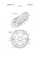
- the apparatus is composed of a multi-part outer wall 1, 2, having a cutting appliance 3 at its forward end, and accommodating therein, inter-alia, a conveyor 4.
- the multi-part wall 1, 2 is composed of two relatively movable component parts 1, 2; each part 1, 2 being in the form of a group of elongate parallel plank-like members 11, 12 respectively.
- the members 11, 12 are all arranged around a common circumferential path and evenly distributed thereabout with gaps 13 between the individual members 11, 12.
- the members 11, 12 are alternately staggered in a circumferential sense with each member 11 disposed between two of the members 12 and vice versa. As shown in FIGS.
- the outermost faces of the members 12 forming the rear wall component 2 are disposed slightly radially outwards from the outermost faces of the members 11 forming the forward wall component.
- the members 11, 12 can also be offset longitudinally (FIGS. 1 and 2) at certain operational stages so that the members 11, collectively constituting the forward wall component 1, are disposed forwardly of the members 12, collectively constituting the rear wall component 2.
- Each component 1, 2 is provided with an arcuate floor section 15 and the section 15 of the rear component 2 is covered by a base plate 16.
- the members 11, 12 are each of trapezoidal cross-section with a tapered knifeedge at its forward end.
- the members 11 are supported on three axially spaced expandible support devices 5, 6, 7 and similarly the members 12 are supported on three axially spaced expandible support devices 8, 9, 10.
- the devices -10 are arranged in pairs, 5, 8; 6, 9; 7, 10; as shown in FIG. 2.
- Each device 5-10 is constructed as a pair of matching half-rings interconnected at their adjacent ends with piston and cylinder units 14.
- the units 14 can be operated to urge the ends of the half-rings apart or to draw these ends together. In this way the devices 5-10 can be contracted or expanded to brace the members 11, 12 against the surface of a tunnel.
- Double-acting piston and cylinder units 17 are used to alternately advance the wall components 1, 2 in the direction of the working face 31 in front of the cutting appliance 3 as described hereinafter.
- the units 17 are pivotably attached between brackets 18, secured to the device 6, and the device 10.
- the cutting appliance 3 which is designed to remove material from the face 31, is provided with a cutting locate within recesses defined by brackets 20 carried by the devices 5, 6.
- a plurality of piston and cylinder units 33 are pivotably connected between brackets 35 attached to the frame 22. The mountings of the units 33 are displaceable longitudinally and the units 33 are used to retract the frame 22 and thereby the cutting head 23 into the wall component 1.
- piston and cylinder units 29 are also connected between the device 10 and the frame 22. These units 29 have detachable plug-like end connections 30 enabling them to be removed from the device 10. The units 29 are used to advance the head 23 from the wall component 1 towards the face 31.
- the head 23 is driven by means of motors 24 carried by the frame 22.
- the motors 24 are coupled to the head 23 via gearing 25 which meshes with a toothed ring.
- the head 23 has a number of radial arms 26 with removable end pieces 27 acting as holders for cutters 32.
- Means, in the form of piston and cylinder units 28, is provided for aligning the cutting head 23.
- the units 28 are connected between the support means for the head 23 and the frame 22.
- the operation of the apparatus is as follows Assume that the units 14 of the devices 8, 9, 10 are operated to expand the devices 8, 9, 10 and thereby brace the rear wall component 2 against the tunnel surface. The rear wall component 2 then forms an abutment whereby the forward wall component 1 can be advanced. To this end, the units 14 of the devices 5, 6, 7 are relieved and the units 17 and 29 are extended to advance the forward wall component 1 and the cutting appliance 3 towards the face 31. The head 23 is thus urged towards the face 31 and is operated by the motors24 to detach material from the face 31. This material is transferred rearwardly of the apparatus by the conveyor 4. When this advance is completed the units 14 of the devices 5, 6, 7 are operated to expand the devices 5, 6, 7 and brace the forward wall component 1 against the tunnel surface. The units 14 of the devices 8, 9, 10 can now be relieved and the units 17 operated to draw up the rear wall component 2 which is then re-braced. This cycle can then be repeated to progressively lengthen the tunnel.
- This machine may comprise means for installing tunnel lining sections end-to-end so as to provide a permanent support for the tunnel rearwardly of the apparatus.
- This rear machine may also be provided with a conveyor which receives material from the conveyor 4 and conveys such material rearwardly of the entire working.
Landscapes
- Engineering & Computer Science (AREA)
- Mining & Mineral Resources (AREA)
- Environmental & Geological Engineering (AREA)
- Life Sciences & Earth Sciences (AREA)
- General Life Sciences & Earth Sciences (AREA)
- Geochemistry & Mineralogy (AREA)
- Geology (AREA)
- Excavating Of Shafts Or Tunnels (AREA)
Applications Claiming Priority (1)
| Application Number | Priority Date | Filing Date | Title |
|---|---|---|---|
| DE19712144862 DE2144862C3 (de) | 1971-09-08 | Tunnelvortriebsmaschine mit einem Messerschild und Verfahren zum Vortrieb eines Tunnels |
Publications (1)
| Publication Number | Publication Date |
|---|---|
| US3800549A true US3800549A (en) | 1974-04-02 |
Family
ID=5818963
Family Applications (1)
| Application Number | Title | Priority Date | Filing Date |
|---|---|---|---|
| US00283898A Expired - Lifetime US3800549A (en) | 1971-09-08 | 1972-08-25 | Tunnelling apparatus |
Country Status (5)
| Country | Link |
|---|---|
| US (1) | US3800549A (enExample) |
| JP (1) | JPS5623038B2 (enExample) |
| CH (1) | CH558856A (enExample) |
| FR (1) | FR2152749B1 (enExample) |
| GB (1) | GB1400192A (enExample) |
Cited By (14)
| Publication number | Priority date | Publication date | Assignee | Title |
|---|---|---|---|---|
| US3889479A (en) * | 1972-08-11 | 1975-06-17 | Gewerk Eisenhuette Westfalia | Means for displacing structures |
| US3903707A (en) * | 1973-03-24 | 1975-09-09 | Gewerk Eisenhuette Westfalia | Tunneling shields |
| US3989302A (en) * | 1975-07-25 | 1976-11-02 | Dresser Industries, Inc. | Continuous roof support system for tunnel boring |
| US4010616A (en) * | 1975-09-23 | 1977-03-08 | Richard Lovat | Rib expander |
| US4012916A (en) * | 1974-12-23 | 1977-03-22 | Gewerkschaft Eisenhutte Westfalia | Apparatus for constructing underground tunnels |
| US4022029A (en) * | 1975-02-27 | 1977-05-10 | Gewerkschaft Eisenhutte Westfalia | Useful improvements in apparatus for, and in methods of, constructing a tunnel |
| JPS5280628A (en) * | 1975-12-26 | 1977-07-06 | Koken Kk | Partition injection shield machine |
| US4073153A (en) * | 1975-10-21 | 1978-02-14 | Gewerkschaft Eisenhutte Westfalia | Drive shields for tunnelling |
| US4140345A (en) * | 1976-10-05 | 1979-02-20 | Babendererde Siegmund H F L M | Tunnel-excavating machine with shield formed of segments |
| US4173421A (en) * | 1976-10-15 | 1979-11-06 | Gewerkschaft Eisenhutte Westfalia | Shield apparatus for use in tunnelling or mining |
| US4265565A (en) * | 1977-09-24 | 1981-05-05 | Gewerkschaft Eisenhutte Westfalia | Tunnel drive shield |
| US4443134A (en) * | 1980-07-16 | 1984-04-17 | Klockner-Werke Aktiengesellschaft | Yieldable roof support for mine passages and the like |
| EP1033473A1 (en) * | 1999-03-03 | 2000-09-06 | C & M McNALLY ENGINEERING Corp. | Method and apparatus for feeding a tunnel roof support system from the roof shield of a Tbm |
| CN111852491A (zh) * | 2020-07-17 | 2020-10-30 | 中国水利水电第六工程局有限公司 | 一种tbm通过长距离软弱泥化岩断层的方法 |
Families Citing this family (5)
| Publication number | Priority date | Publication date | Assignee | Title |
|---|---|---|---|---|
| JPS5138748A (ja) * | 1974-09-27 | 1976-03-31 | Kubota Ltd | Tonnerukoho |
| AT354504B (de) * | 1975-05-10 | 1979-01-10 | Gewerk Eisenhuette Westfalia | Vortriebsschild fuer den tunnel- oder stollen- vortrieb u. dgl. |
| DE2612169C3 (de) * | 1976-03-23 | 1980-08-28 | Gewerkschaft Eisenhuette Westfalia, 4670 Luenen | Steuervorrichtung für einen Messerschild |
| DE2654422C2 (de) * | 1976-12-01 | 1985-01-17 | Gewerkschaft Eisenhütte Westfalia, 4670 Lünen | Verbauschild für den Vortrieb von Tunnels, Stollen o.dgl. |
| JPS5428409A (en) * | 1977-08-04 | 1979-03-03 | Uemura Koichi | Method of propelling cylindrical body with complex cutting edge and its device |
Citations (6)
| Publication number | Priority date | Publication date | Assignee | Title |
|---|---|---|---|---|
| DE1109630B (de) * | 1958-12-27 | 1961-06-29 | Bochumer Eisen Heintzmann | Ausbaukammer fuer Streckenvortriebe, insbesondere im untertaegigen Grubenbetrieb |
| US3355215A (en) * | 1966-11-07 | 1967-11-28 | Smith Ind International Inc | Oscillating tunneling machine |
| US3379024A (en) * | 1965-04-13 | 1968-04-23 | Josef Wohlmeyer | Machine for constructing lined ducts through rock |
| US3411826A (en) * | 1966-05-26 | 1968-11-19 | Smith Ind International Inc | Tunnel boring machine |
| US3613384A (en) * | 1969-02-10 | 1971-10-19 | J Donovan Jacobs | Method and apparatus for advancing tunnel supports |
| US3672726A (en) * | 1970-07-20 | 1972-06-27 | Robert L House | Tunnel boring apparatus |
-
1972
- 1972-04-28 CH CH636172A patent/CH558856A/xx not_active IP Right Cessation
- 1972-08-25 US US00283898A patent/US3800549A/en not_active Expired - Lifetime
- 1972-09-06 GB GB4135972A patent/GB1400192A/en not_active Expired
- 1972-09-08 FR FR7231834A patent/FR2152749B1/fr not_active Expired
- 1972-09-08 JP JP8965672A patent/JPS5623038B2/ja not_active Expired
Patent Citations (6)
| Publication number | Priority date | Publication date | Assignee | Title |
|---|---|---|---|---|
| DE1109630B (de) * | 1958-12-27 | 1961-06-29 | Bochumer Eisen Heintzmann | Ausbaukammer fuer Streckenvortriebe, insbesondere im untertaegigen Grubenbetrieb |
| US3379024A (en) * | 1965-04-13 | 1968-04-23 | Josef Wohlmeyer | Machine for constructing lined ducts through rock |
| US3411826A (en) * | 1966-05-26 | 1968-11-19 | Smith Ind International Inc | Tunnel boring machine |
| US3355215A (en) * | 1966-11-07 | 1967-11-28 | Smith Ind International Inc | Oscillating tunneling machine |
| US3613384A (en) * | 1969-02-10 | 1971-10-19 | J Donovan Jacobs | Method and apparatus for advancing tunnel supports |
| US3672726A (en) * | 1970-07-20 | 1972-06-27 | Robert L House | Tunnel boring apparatus |
Cited By (14)
| Publication number | Priority date | Publication date | Assignee | Title |
|---|---|---|---|---|
| US3889479A (en) * | 1972-08-11 | 1975-06-17 | Gewerk Eisenhuette Westfalia | Means for displacing structures |
| US3903707A (en) * | 1973-03-24 | 1975-09-09 | Gewerk Eisenhuette Westfalia | Tunneling shields |
| US4012916A (en) * | 1974-12-23 | 1977-03-22 | Gewerkschaft Eisenhutte Westfalia | Apparatus for constructing underground tunnels |
| US4022029A (en) * | 1975-02-27 | 1977-05-10 | Gewerkschaft Eisenhutte Westfalia | Useful improvements in apparatus for, and in methods of, constructing a tunnel |
| US3989302A (en) * | 1975-07-25 | 1976-11-02 | Dresser Industries, Inc. | Continuous roof support system for tunnel boring |
| US4010616A (en) * | 1975-09-23 | 1977-03-08 | Richard Lovat | Rib expander |
| US4073153A (en) * | 1975-10-21 | 1978-02-14 | Gewerkschaft Eisenhutte Westfalia | Drive shields for tunnelling |
| JPS5280628A (en) * | 1975-12-26 | 1977-07-06 | Koken Kk | Partition injection shield machine |
| US4140345A (en) * | 1976-10-05 | 1979-02-20 | Babendererde Siegmund H F L M | Tunnel-excavating machine with shield formed of segments |
| US4173421A (en) * | 1976-10-15 | 1979-11-06 | Gewerkschaft Eisenhutte Westfalia | Shield apparatus for use in tunnelling or mining |
| US4265565A (en) * | 1977-09-24 | 1981-05-05 | Gewerkschaft Eisenhutte Westfalia | Tunnel drive shield |
| US4443134A (en) * | 1980-07-16 | 1984-04-17 | Klockner-Werke Aktiengesellschaft | Yieldable roof support for mine passages and the like |
| EP1033473A1 (en) * | 1999-03-03 | 2000-09-06 | C & M McNALLY ENGINEERING Corp. | Method and apparatus for feeding a tunnel roof support system from the roof shield of a Tbm |
| CN111852491A (zh) * | 2020-07-17 | 2020-10-30 | 中国水利水电第六工程局有限公司 | 一种tbm通过长距离软弱泥化岩断层的方法 |
Also Published As
| Publication number | Publication date |
|---|---|
| DE2144862B2 (de) | 1977-03-31 |
| DE2144862A1 (de) | 1973-03-15 |
| CH558856A (de) | 1975-02-14 |
| FR2152749A1 (enExample) | 1973-04-27 |
| JPS4862232A (enExample) | 1973-08-30 |
| GB1400192A (en) | 1975-07-16 |
| FR2152749B1 (enExample) | 1978-03-03 |
| JPS5623038B2 (enExample) | 1981-05-28 |
Similar Documents
| Publication | Publication Date | Title |
|---|---|---|
| US3800549A (en) | Tunnelling apparatus | |
| US4043137A (en) | Apparatus for and a method of constructing a tunnel | |
| US4420188A (en) | Double shield tunnel boring machine | |
| US3581507A (en) | Tunneling shield | |
| GB1319871A (en) | Tunneling machines | |
| US4118938A (en) | Apparatus for and method of driving tunnels | |
| CA1335207C (en) | Shuffling quadrishoe tunnel boring machine | |
| US4055959A (en) | Apparatus for use in mining or tunnelling installations | |
| US3916630A (en) | Tunneling methods and apparatus | |
| US3467436A (en) | Tunnelling machine with rotatable cutter carrying arm for 360 cutting | |
| US4120165A (en) | Methods of and apparatus for driving tunnels | |
| GB2038904A (en) | Tunnel driving apparatus | |
| US2760766A (en) | Tunnel excavator having rotary cutters mounted upon a rotatable cutting head | |
| US3523426A (en) | Process and apparatus for driving tunnels in rock having zones differing in stability | |
| US4140345A (en) | Tunnel-excavating machine with shield formed of segments | |
| US4073153A (en) | Drive shields for tunnelling | |
| US3818713A (en) | Driving of tunnels | |
| EP0272859A1 (en) | A tunnel boring machine | |
| US4143519A (en) | Drive shield | |
| GB1599117A (en) | Support systems for mineral mining installations | |
| DE1101479B (de) | Verfahren zum Herstellen eines Tunnels oder Stollens durch Vortrieb eines im Erdreich verbleibenden Tunnelrohres | |
| US2134478A (en) | Tunneling machine | |
| US4265565A (en) | Tunnel drive shield | |
| US4134620A (en) | Channelling machine for cutting a preliminary groove around the working face of a tunnel | |
| US3989302A (en) | Continuous roof support system for tunnel boring |