US3797671A - Collapsible structure for a shelving arrangement - Google Patents
Collapsible structure for a shelving arrangement Download PDFInfo
- Publication number
- US3797671A US3797671A US00252661A US3797671DA US3797671A US 3797671 A US3797671 A US 3797671A US 00252661 A US00252661 A US 00252661A US 3797671D A US3797671D A US 3797671DA US 3797671 A US3797671 A US 3797671A
- Authority
- US
- United States
- Prior art keywords
- posts
- fingers
- post
- perforations
- beams
- Prior art date
- Legal status (The legal status is an assumption and is not a legal conclusion. Google has not performed a legal analysis and makes no representation as to the accuracy of the status listed.)
- Expired - Lifetime
Links
- 239000002184 metal Substances 0.000 claims description 10
- 239000000463 material Substances 0.000 claims description 4
- 230000007423 decrease Effects 0.000 claims description 2
- 210000003414 extremity Anatomy 0.000 description 6
- 230000003247 decreasing effect Effects 0.000 description 2
- 230000000694 effects Effects 0.000 description 2
- 230000004048 modification Effects 0.000 description 2
- 238000012986 modification Methods 0.000 description 2
- 230000000903 blocking effect Effects 0.000 description 1
- 238000010276 construction Methods 0.000 description 1
- 230000003467 diminishing effect Effects 0.000 description 1
- 230000008030 elimination Effects 0.000 description 1
- 238000003379 elimination reaction Methods 0.000 description 1
- 238000009434 installation Methods 0.000 description 1
- 210000003141 lower extremity Anatomy 0.000 description 1
- 238000004519 manufacturing process Methods 0.000 description 1
- 230000008707 rearrangement Effects 0.000 description 1
- 230000002787 reinforcement Effects 0.000 description 1
- 238000007493 shaping process Methods 0.000 description 1
- 229910000679 solder Inorganic materials 0.000 description 1
- 210000001364 upper extremity Anatomy 0.000 description 1
Images

Classifications
-
- A—HUMAN NECESSITIES
- A47—FURNITURE; DOMESTIC ARTICLES OR APPLIANCES; COFFEE MILLS; SPICE MILLS; SUCTION CLEANERS IN GENERAL
- A47B—TABLES; DESKS; OFFICE FURNITURE; CABINETS; DRAWERS; GENERAL DETAILS OF FURNITURE
- A47B57/00—Cabinets, racks or shelf units, characterised by features for adjusting shelves or partitions
- A47B57/30—Cabinets, racks or shelf units, characterised by features for adjusting shelves or partitions with means for adjusting the height of detachable shelf supports
- A47B57/40—Cabinets, racks or shelf units, characterised by features for adjusting shelves or partitions with means for adjusting the height of detachable shelf supports consisting of hooks coacting with openings
-
- A—HUMAN NECESSITIES
- A47—FURNITURE; DOMESTIC ARTICLES OR APPLIANCES; COFFEE MILLS; SPICE MILLS; SUCTION CLEANERS IN GENERAL
- A47B—TABLES; DESKS; OFFICE FURNITURE; CABINETS; DRAWERS; GENERAL DETAILS OF FURNITURE
- A47B96/00—Details of cabinets, racks or shelf units not covered by a single one of groups A47B43/00 - A47B95/00; General details of furniture
- A47B96/14—Bars, uprights, struts, or like supports, for cabinets, brackets, or the like
Definitions
- the present invention concerns a dismountable or collapsible storage rack structure from which metallic shelves can be assembled and, more especially, to shelves for pallets.
- Said structure includes vertical posts connected in pairs by cross-bars to form rigid frames.
- Horizontal, load supporting beams are mounted in a manner adjustable to different heights between the posts of two adjacent parallel frames. Connecting means on the ends of said beams and on said posts provide for the rigid interlocking of the various components of the shelf structure.
- the present vertical posts have a constant cross-sectional size throughout the vertical length thereof, which size must be calculated as a function of the maximum load to be supported by the structure while, in fact, this maximum load is exerted only on the lower ends of the posts, and consequently increases uselessly the cost of the shelves thusly fabricated.
- each vertical post is comprised of a selected number of standard elements in the form of truncated cones which are assembled in a side-by-side manner and secured to each other by means of appropriate tightening collars, to provide finally a truncated post having a constantly decreasing cross section from the base to the top.
- the load supported by the automatically narrowing posts is in proportion as the height is raised and, this being almost continuous, it will be sufficient that the lower portion of the post be capable of supporting the maximum load.
- the elements of the truncated posts are comprised of hollow members having substantially triangular cross sections, which are obtained by folding metal sheets of which the two longitudinal edges are fitted one against the other in a manner to form a rigid external flange on which are mounted the horizontal, load supporting beams.
- These posts are disposed so that their flanges extend toward the interior of the frames, are coplanar and are perpendicular to a horizontal plane when the posts are upright.
- Such cross sections are very easy to make by means of a shaping press and besides give to the mounted shelves a significant aesthetic appearance.
- the horizontal, load supporting beams are provided with hollow cross sections of triangular profile, likewise obtained by folding sheets of metal, of which the two ends are flattened and cooperate with some useful perforations at regular intervals along the vertical flanges of the truncated posts.
- the beams are arranged in a manner so as to support the load on their planar faces.
- the flattened ends of the beams are comprised of at least two parallel, horizontal and spaced fingers which cooperate with some separate perforations on the posts, these perforations being sufficiently large to receive simultaneously the fingers of two adjacent beams arranged in lengthwise extension of each other.
- the fingers of the beams are provided with downwardly opening grooves which cooperate with the means defining the lower edge of corresponding perforation of the post, in order to assure the correct positioning of the beams between the posts.
- each beam has at least two parallel, horizontal and spaced fingers at one of its flattened ends, these fingers cooperating with some separate perforations in the post, while its other end has an inverted U-shaped section which is understood to receive its support on the fingers at the end of an adjacent beam extending through the perforations of the corresponding post.
- the beams which are arranged in lengthwise extension of each other are rigidly connected together by means of bolts or the like.
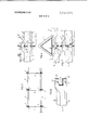
- FIG. 1 is a front elevational View of a shelf structure for pallets and embodying the invention
- FIG. 2 is a side elevational view of this structure
- H6. 3 is a schematic sectional view taken along the line Ill-Ill of H6. 1-,
- FIG. 4 is a perspective view of one end of a horizontal beam of the structure
- H6. 5 is a fragmentary, cross-sectional and enlarged view showing the connection between the horizontal beams and the vertical posts of the structure;
- H0. 6 is a cross-sectional view taken along the line VIVI of FIG. 5'.
- FIG. 7 is a cross-sectional view similar to that of FIG. 5, but disclosing an alternate embodiment of the invention.
- the storage rack structure represented in the F168. 1 to 3, inclusive, is comprised essentially of some vertical posts 1, some cross-bars 2 and some horizontal beams 3 for the support of palletized loads.
- the vertical posts 1 are connected, two-by-two, by the crossbars 2 and they also form rigid frames.
- the horizontal beams 3 are mounted in a manner adjustable to different heights between the posts of adjacent frames arranged in parallel, due to means which will be described in more detail hereinafter.
- each vertical post 1 is comprised of a certain number of standard elements 4 of elongated truncated form having, for example, an unbroken length of two meters. These elements are not interlocked together but are simply assembled end-to end in a rigid and contiguous manner by means of gripping collars of appropriate form.
- the posts 1 thus constituted are thus likewise truncated and therefore, they have a continuously decreasing cross section from bottom to top. It will be noted, moreover, that each of the posts is supported on the floor by means of a base plate 6.
- the assembly collars 5 are fastened tightly around the elements 4 by means of bolts and one can thus take advantage of this by placing the crossbars 2 on the same level as these collars, thereby permitting them to be secured by these same bolts. Needless to say, one should also provide crossbars at the upper and lower extremities of the posts 1. These crossbars are preferably flanged to increase their rigidity, and one could moreover provide cross braces for reinforcement between the successive crossbars.
- the truncated elements 4 are comprised of hollow members with essentially triangular cross sections. These members are obtained in a very simple manner, by folding sheet metal in a folder press. The two lengthwise edges of the member are moreover arranged against each other in a manner to thus form a rigid, exterior flange 7, disposed perpendicularly with respect to one of the flat sides of the member. In this flange 7 are formed at regular intervals some rectangular perforations 8 permitting the mounting of horizontal beams 3, as it will be seen hereinafter. The perforations 8 are also suited to receive the bolts serving in the fastening of the collars 5 or the crossbars 2.
- the flanges 7 of the members are intended to be located in the plane of the frames formed by the posts, namely, in the plane of the crossbars 2, thereby extending toward the interior of these frames. It is proper to note that these members are furnished in the manner that when the vertical post 1 is erected, its flange 7 would be strictly perpendicular to a horizontal plane, although the body of the post would be truncated, in order to facilitate the mounting of the beams and the crossbars of the structure. lt can also be advantageous to solder at points on the two edges of the member which form the flange 7, in order to increase the rigidity of the members and consequently that of each entire post.
- the horizontal beams 3 which support the load are likewise made from hollow members with essentially triangular cross sections, obtained by folding sheet metal.
- the lower portion of the beam is formed by the two lengthwise edges 9 of the member, edges which could be advantageously soldered at points while the upper portion of the beam is formed by a flat surface 10 designed to support the load.
- the two ends of the member are, moreover, flattened in a plane perpendicular to the flat surface 10 and they each have a central, rectangular cut out 11 forming on opposite sides thereof two parallel and spaced fingers 12 which are intended to cooperate with the perforations 8 in the vertical posts 1.
- Each of these fingers 12 has, furthermore, in its lower edge a notch 13 the purpose of which will become more apparent hereinafter.
- the manner in which the horizontal beams are attached to the posts 1 is illustrated in the FIGS. 5 and 6.
- the spacing between the fingers 12 corresponds exactly to the spacing of the perforations 8, so that these fingers can be inserted simultaneously into two consecutive perforations of the post, at the desired location.
- the width of these perforations 8 is sufficient that they can receive simultaneously the fingers of two adjacent beams arranged in lengthwise extension of each other, which corresponds to the type of an installation most frequently demanded.
- the fingers 12 are positioned in the perforations 8 in such a manner that the means defining the lower edges of these perforations are received into the notches 13 of the fingers, which assures the lengthwise positioning of the beam.
- This arrangement contributes moreover to assure the rigidity of the structure in the longitudinal plane.
- a free space which can advantageously be filled by means of a blocking pin.
- the dimension of the beams is a function of the load that they will support and that they can thus in such event have more than two fingers l2, conveniently spaced, at each of their extremities.
- the two extremities of the horizontal beam 3 are different.
- One of these extremities is in the same form as the embodiment of FIG. 4, namely, it has two parallel and spaced fingers l2 intended to cooperate with the perforation 8 of the vertical posts 1.
- the opposite end of the beam is not equipped with a finger and has an enlargement 14 of inverted U-shaped cross section which is arranged to cover the ends of the fingers of the adjacent beam, as shown in FIG. 7.
- the perforations 8 do not need to be as wide as in the form of the preceding embodiment, since they receive only one finger at a time. It is no longer necessary to provide the positioning notches on these fingers. It will be noted in fact that the beam has no need for any extension and that it can consequently abut against the flanges 7 of the posts at each of its extremities, that which assures its longitudinal position. Thus, the cut out 11 of the beam will be less deep than in the form of the preceding embodiment, in such a manner that the inner end of this cut out can abut against the side of the corresponding flange 7.
- the extremity of the enlargement 14 should be slightly rounded, in order that one can mount or dismount the beam by pivoting it in a vertical plane. From this fact, it will be equally advantageous to interconnect these beams to each other by means of a bolt such as that at 15, located on the level of the lower finger of the beam in order to prevent the accidental dislodging of a beam due to an ever possible forcing move by the lift truck during the handling of the palletized loads.
- a bolt moreover can also be provided in the manner of the embodiment of FlG. 5 in order to strengthen further the rigidity of the structure involved.
- FIG. 7 it is proper moreover to state that the alternate embodiment shown in FIG. 7 is most especially designed with shelves in which the horizontal beams for supporting the load are all mounted in lengthwise extension of each other. It is nevertheless possible if the need arises, to mount the beams in an independent manner, by utilizing a special support affixed to the corresponding vertical post and having fingers adapted to be received into the enlargement 14 of the beam. Such supports will be moreover of such form as is required by at least the one extremity of the shelf.
- the shelves according to the invention require, for a given load, a smaller quantity of metal than existing shelves, while at the same time being as strong. They are thus less costly and of less weight. They provide furthermore a very great flexibility of utilization because they are entirely collapsible, in that it comprises the vertical posts which can thus be erected at the desired height directly at the place of construction of the shelves.
- the shelves according to the invention are very pleasing in appearance when assembled, due to the particular form of the posts and of the beam.
- a collapsible storage rack structure having plural pairs of elongated vertical posts, plural cross-bars connected between the vertical posts of each pair to form a rigid rectangular frame, and a plurality of elongated horizontal beams extending between and connected to adjacent pairs of substantially parallel rectangular frames, said beams being connected to said posts so as to be adjustable to different heights, comprising the improvement wherein each post comprises a plurality of elongated post sections each of truncated form, said post sections being positioned in end-to-end relation ship so that said post is truncated and has a crosssection which continuously decreases from the lower end to the upper end thereof, and collar means coacting with adjacent post sections for fixedly connecting same together in said end-to-end relationship.
- each post section comprises a hollow member of substantially triangular cross section and formed from sheetlike metal, the two lengthwise edges of each hollow member being placed against each other and forming a rigid platelilre external flange projecting outwardly from one side of the triangular cross-section, said horizontal beams extending between and being supported on the flanges of a pair of posts and the pair of posts in each frame being arranged so that the flanges extend inwardly toward each other and are substantially coplanar.
- said horizontal beam comprises a hollow member of triangular cross-section and formed from sheetlilre metal, the two ends of said beam being flattened and cooperating with perforations cut at regular intervals through the external flanges of the truncated posts.
- each flattened end of the beam has at least two horizontal, parallel and spaced fingers which project through different perforations in the post, said perforations being sufficiently wide to receive simultaneously in side-byside relationship the fingers of two adjacent beams which are positioned in lengthwise extension of each w other.
- each beam has at least two horizontal, parallel and spaced fingers at one of its ends, said fingers projecting through separate perforations in said post, the other end of said beam having an inverted U-shaped portion arranged for support on the fingers of an adjacent beam as they project through the perforations of the corresponding post.
- each post section comprises a hollow tubular member formed from. sheetlike material, the two lengthwise edges of said hollow member being placed against each other and forming a rigid platelike external flange projecting outwardly from said hollow member, said platelike flange extending longitudinally throughout the complete length of said hollow member, the individual platelilte flanges of the individual post sections being aligned with one another when said post sections are assembled in end-to-end relationship, the external flange of each hollow member having a plurality of perforations extending transversely therethrough with said plurality of perforations being spaced from one another and disposed within a row extending in the longitudinal direction of said hollow member, and the pair of posts in each frame being arranged so that the flanges extend inwardly toward one another and are substantially coplanar; and
- each said horizontal beam extending between and being supported on the flanges of a pair of posts, each said horizontal beam being flattened and cooperating with the perforations formed in the external flanges of said posts, at least one of the flattened ends of said beam being comprised of at least two substantially parallel and horizontally elongated fingers projecting outwardly from the end of said beam substantially in the longitudinal direction thereof, said two fingers being vertically spaced one above the other so as to project through two difi'erent perforations formed in said external flange, said fingers projecting through and beyond the other side of said flange for a substantial distance.
- each said beam comprises a hollow tubular member formed from sheetlike material, said hollow member having at least one flat surface positioned so as to face upwardly, and the opposite ends of said hollow member being flattened and disposed for cooperation with the perforations formed in said vertical flanges for securing said horizontal beams to said posts.
Landscapes
- Pallets (AREA)
- Assembled Shelves (AREA)
Applications Claiming Priority (1)
| Application Number | Priority Date | Filing Date | Title |
|---|---|---|---|
| FR717117078A FR2137035B1 (enExample) | 1971-05-12 | 1971-05-12 |
Publications (1)
| Publication Number | Publication Date |
|---|---|
| US3797671A true US3797671A (en) | 1974-03-19 |
Family
ID=9076879
Family Applications (1)
| Application Number | Title | Priority Date | Filing Date |
|---|---|---|---|
| US00252661A Expired - Lifetime US3797671A (en) | 1971-05-12 | 1972-05-12 | Collapsible structure for a shelving arrangement |
Country Status (3)
| Country | Link |
|---|---|
| US (1) | US3797671A (enExample) |
| DE (1) | DE2222747A1 (enExample) |
| FR (1) | FR2137035B1 (enExample) |
Cited By (8)
| Publication number | Priority date | Publication date | Assignee | Title |
|---|---|---|---|---|
| US4039132A (en) * | 1976-01-05 | 1977-08-02 | Fournier Peter R | Plant support structure |
| WO1983000853A1 (en) * | 1981-09-10 | 1983-03-17 | Electrolux Const Ab | Device for a storage rack |
| US4552270A (en) * | 1984-03-01 | 1985-11-12 | Lentz Scott B | Storage system for athletic equipment or the like |
| US5368174A (en) * | 1992-08-07 | 1994-11-29 | Unr Industries, Inc. | Storage rack beam having surface enabling indicia at high or low elevation to be easily read |
| US20060049726A1 (en) * | 2004-09-07 | 2006-03-09 | Sanyo Electric Co., Ltd. | Showcase |
| EP2537627A1 (de) * | 2011-06-21 | 2012-12-26 | Dirk Brackelmann | Verfahren und Mittel zur Instandsetzung von Metallregalen |
| CN108741974A (zh) * | 2018-04-03 | 2018-11-06 | 温州商学院 | 一种无限拓展式多角度壁画展示装置 |
| US10302115B2 (en) | 2016-10-18 | 2019-05-28 | Whirlpool Corporation | Spring clip upright connection for rack shelving |
Families Citing this family (2)
| Publication number | Priority date | Publication date | Assignee | Title |
|---|---|---|---|---|
| FR2609760A1 (fr) * | 1987-01-19 | 1988-07-22 | Alser Sa | Barre support notamment pour broches, etageres, plateaux et analogues, et procede de fabrication d'une telle barre |
| IT1269074B (it) * | 1994-01-20 | 1997-03-21 | Rosss Dei F Lli Bettini S N C | Una traversa in profilato tubolare per il collegamento dei montanti in scaffalature metalliche |
Citations (8)
| Publication number | Priority date | Publication date | Assignee | Title |
|---|---|---|---|---|
| BE533722A (enExample) * | ||||
| US955734A (en) * | 1909-04-26 | 1910-04-19 | Joseph Wolkerstorfer | Display-rack. |
| US1266749A (en) * | 1917-10-29 | 1918-05-21 | James A Abbott | Artificial tree. |
| US2914190A (en) * | 1956-11-15 | 1959-11-24 | Schenley Ind Inc | Shelving for bottles and other goods |
| GB873519A (en) * | 1960-04-26 | 1961-07-26 | Equipment Mfg Inc | Improvements in or relating to rack construction |
| US3278043A (en) * | 1965-02-16 | 1966-10-11 | Palmer Shile Co | Storage rack |
| NL6602379A (enExample) * | 1965-10-19 | 1967-04-20 | ||
| US3592345A (en) * | 1969-04-04 | 1971-07-13 | Bernard Franklin Co Inc | Erectible metal shelving |
-
1971
- 1971-05-12 FR FR717117078A patent/FR2137035B1/fr not_active Expired
-
1972
- 1972-05-09 DE DE19722222747 patent/DE2222747A1/de active Pending
- 1972-05-12 US US00252661A patent/US3797671A/en not_active Expired - Lifetime
Patent Citations (8)
| Publication number | Priority date | Publication date | Assignee | Title |
|---|---|---|---|---|
| BE533722A (enExample) * | ||||
| US955734A (en) * | 1909-04-26 | 1910-04-19 | Joseph Wolkerstorfer | Display-rack. |
| US1266749A (en) * | 1917-10-29 | 1918-05-21 | James A Abbott | Artificial tree. |
| US2914190A (en) * | 1956-11-15 | 1959-11-24 | Schenley Ind Inc | Shelving for bottles and other goods |
| GB873519A (en) * | 1960-04-26 | 1961-07-26 | Equipment Mfg Inc | Improvements in or relating to rack construction |
| US3278043A (en) * | 1965-02-16 | 1966-10-11 | Palmer Shile Co | Storage rack |
| NL6602379A (enExample) * | 1965-10-19 | 1967-04-20 | ||
| US3592345A (en) * | 1969-04-04 | 1971-07-13 | Bernard Franklin Co Inc | Erectible metal shelving |
Cited By (15)
| Publication number | Priority date | Publication date | Assignee | Title |
|---|---|---|---|---|
| US4039132A (en) * | 1976-01-05 | 1977-08-02 | Fournier Peter R | Plant support structure |
| WO1983000853A1 (en) * | 1981-09-10 | 1983-03-17 | Electrolux Const Ab | Device for a storage rack |
| US4552270A (en) * | 1984-03-01 | 1985-11-12 | Lentz Scott B | Storage system for athletic equipment or the like |
| US5526945A (en) * | 1992-08-07 | 1996-06-18 | Unarco Material Handling, Inc. | Storage rack having support beam with channel profile and inclinded surface |
| US5386917A (en) * | 1992-08-07 | 1995-02-07 | Unr Industries, Inc. | Storage rack system with fire extinguishing device |
| US5492231A (en) * | 1992-08-07 | 1996-02-20 | Unarco Material Handling, Inc. | Storage rack having support seam with outer, generally arcuate, indicia-receiving surface |
| US5368174A (en) * | 1992-08-07 | 1994-11-29 | Unr Industries, Inc. | Storage rack beam having surface enabling indicia at high or low elevation to be easily read |
| US5655675A (en) * | 1992-08-07 | 1997-08-12 | Unarco Material Handling, Inc. | Storage rack system with fire extinguishing device |
| US5749482A (en) * | 1992-08-07 | 1998-05-12 | Unarco Material Handling, Inc. | Storage rack beam having surface enabling indicia at low elevation to be easily read |
| US20060049726A1 (en) * | 2004-09-07 | 2006-03-09 | Sanyo Electric Co., Ltd. | Showcase |
| EP1632150A3 (en) * | 2004-09-07 | 2006-07-12 | Sanyo Electric Co., Ltd. | Showcase |
| EP2537627A1 (de) * | 2011-06-21 | 2012-12-26 | Dirk Brackelmann | Verfahren und Mittel zur Instandsetzung von Metallregalen |
| US10302115B2 (en) | 2016-10-18 | 2019-05-28 | Whirlpool Corporation | Spring clip upright connection for rack shelving |
| CN108741974A (zh) * | 2018-04-03 | 2018-11-06 | 温州商学院 | 一种无限拓展式多角度壁画展示装置 |
| CN108741974B (zh) * | 2018-04-03 | 2019-04-30 | 温州商学院 | 一种无限拓展式多角度壁画展示装置 |
Also Published As
| Publication number | Publication date |
|---|---|
| FR2137035A1 (enExample) | 1972-12-29 |
| FR2137035B1 (enExample) | 1973-05-11 |
| DE2222747A1 (de) | 1972-12-14 |
Similar Documents
| Publication | Publication Date | Title |
|---|---|---|
| US3465895A (en) | Storage rack | |
| US5452811A (en) | Stackable partitioned shipping container | |
| US4324076A (en) | Wall units | |
| US5704497A (en) | Rotating display rack | |
| US4173934A (en) | Shelving structure | |
| DE2312746C2 (de) | Gestell mit Trägern und wenigstens einer Tragsäule | |
| US3797671A (en) | Collapsible structure for a shelving arrangement | |
| US12268298B2 (en) | Industrial rack | |
| US4053246A (en) | Storage rack assembly and mounting clamp therefor | |
| US3942764A (en) | Protective fencing | |
| US3929248A (en) | Divider and partition device for wire | |
| US3679067A (en) | Storage rack and bracket therefor | |
| EP0259787B1 (de) | Warenregal | |
| US6216415B1 (en) | Element of load-bearing structures, especially girders for modular shelves | |
| CA1081661A (en) | Wall unit | |
| GB2163639A (en) | Structural assembly | |
| EP0077885B1 (de) | Palettenregal | |
| RU51466U1 (ru) | Стеллаж (варианты) | |
| US3241685A (en) | Storage rack | |
| AT1059U1 (de) | Regal | |
| JPH071476Y2 (ja) | ネットフェンス | |
| US4795039A (en) | Display apparatus | |
| AT377425B (de) | Zerlegbares regal | |
| US3179073A (en) | Adjustable supporting surfaces | |
| CA1085777A (en) | Shelving structure |