US3789998A - Hoisting equipment including spreader with longitudinal and transverse tilting mechanism - Google Patents
Hoisting equipment including spreader with longitudinal and transverse tilting mechanism Download PDFInfo
- Publication number
- US3789998A US3789998A US00218188A US3789998DA US3789998A US 3789998 A US3789998 A US 3789998A US 00218188 A US00218188 A US 00218188A US 3789998D A US3789998D A US 3789998DA US 3789998 A US3789998 A US 3789998A
- Authority
- US
- United States
- Prior art keywords
- spreader
- frame
- cables
- axis
- unit
- Prior art date
- Legal status (The legal status is an assumption and is not a legal conclusion. Google has not performed a legal analysis and makes no representation as to the accuracy of the status listed.)
- Expired - Lifetime
Links
Images


Classifications
-
- B—PERFORMING OPERATIONS; TRANSPORTING
- B66—HOISTING; LIFTING; HAULING
- B66C—CRANES; LOAD-ENGAGING ELEMENTS OR DEVICES FOR CRANES, CAPSTANS, WINCHES, OR TACKLES
- B66C1/00—Load-engaging elements or devices attached to lifting or lowering gear of cranes or adapted for connection therewith for transmitting lifting forces to articles or groups of articles
- B66C1/10—Load-engaging elements or devices attached to lifting or lowering gear of cranes or adapted for connection therewith for transmitting lifting forces to articles or groups of articles by mechanical means
- B66C1/101—Load-engaging elements or devices attached to lifting or lowering gear of cranes or adapted for connection therewith for transmitting lifting forces to articles or groups of articles by mechanical means for containers
-
- B—PERFORMING OPERATIONS; TRANSPORTING
- B66—HOISTING; LIFTING; HAULING
- B66C—CRANES; LOAD-ENGAGING ELEMENTS OR DEVICES FOR CRANES, CAPSTANS, WINCHES, OR TACKLES
- B66C13/00—Other constructional features or details
- B66C13/04—Auxiliary devices for controlling movements of suspended loads, or preventing cable slack
- B66C13/08—Auxiliary devices for controlling movements of suspended loads, or preventing cable slack for depositing loads in desired attitudes or positions
Definitions
- the equipment includes a crane and cables pendently supporting the spreader from the crane and shortenable and extendable coupling devices associated with the spreader which may be selectively operated to change the effective lengths of at least certain of the cables while independently of the cable-reeling mechanism on the crane.
- a further aspect of the equipment is linear adjustability of each cable with respect to the spreader and the coupling devices.
- a container being lowered under a condition of longitudinal and transverse levelness will tend to wedge within the ships structure and be abraded along its outer vertical surfaces if lowered into the hatch of a container ship having significant list or abnormal trim deviation.
- This problem is amplified by a practice recently adopted in maritime shipment of cargo containers, i.e., the employment of twin spreaders to lower two containers simultaneously into a ships hold.
- a principal object of the present invention is to provide hoisting equipment of more mechanically simple design than at least some of the mechanisms from the prior art.
- Load hoisting equipment as contemplated by this invention comprises in its simplest form a crane, a spreader in pendent relation with the crane, and cables stored on reels in the crane connecting the spreader therewith and providing at least three points of suspension or connection with a frame.
- the first of such points of connection occurs in a vertical plane containing the longitudinal axis of the frame or the spreader.
- the two other points of connection are spaced lengthwise of the frame from the first point but in spaced relation with the vertical plane at opposite sides thereof.
- the reeling mechanism of the crane is constructed for paying out or reeling in the cables at equilinear rates.
- connections of the cables with the spreader at the two latter points be established through longitudinally extendable or shortenable mechanisms for connecting the cables and the spreader, such as hydraulic cylinders, each being attached at one end to a cable and by its other end to the frame.
- Another feature of the invention occurring in a preferred embodiment resides in the provision of a centrally-pivoted rocking beam pivotally attached to, and extending transversely of, the frame at the first point of suspension and supported directly from the crane by two cables which engage the beam near its ends.
- a preferred embodiment includes, as another feature, adjustable terminal mechanism on the spreader for each cable enabling independent linear adjustment of each cable relative to the spreader frame such as needed in the event of cable stretching to establish the neutral or normal level position of the spreader.
- FIG. 1 is a perspective view of a gantry crane including other container hoisting equipment, such as a spreader in pendent relation with a mobile hoisting unit in'position to serve a container ship at dockside;
- container hoisting equipment such as a spreader in pendent relation with a mobile hoisting unit in'position to serve a container ship at dockside;
- FIG. 2 is a fragmentary perspective view of a spreader comprising a master power pack unit and a slave spreader frame illustrating primarily a master unit in accordance with one embodiment of the invention
- FIG. 3 is an elevation in longitudinal section illustrating a crane cable and a crane terminal assembly of the master unit of FIG. 2 for linearly adjusting the cable relative to the spreader;
- FIG. 4 is a fragmentary elevation partly in section illustrating a swivel joint of a fluid cylinder of FIG. 3, with the associated slave spreader unit;
- FIG. 5 is a fragmentary perspective view of a spreader illustrating a type of master unit in accordance with another embodiment
- FIG. 6 is a fragmentary end elevation of the spreader of FIG. 4 illustrating primarily a rocking beam of the master unit with parts sectioned to show the interior construction;
- FIG. 7 is a longitudinal elevation in section of the master unit illustrated in FIGS. 5 and 6;
- FIG. 8 is a fragmentary plan view of a crosshead connection of one of the power source cylinders and a cable terminal fitting shown in FIGS. 5 and 7;
- FIGS. 9 and 10 are schematic, longitudinal and end elevations of one type of spreader employing a single master unit of the invention.
- FIGS. 11 and 12 are schematic, longitudinal and end views of an expandable spreader incorporating two master units attached to an elongate type of slave unit along parallel pivotal transverse axes;
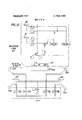
- FIG. 13 is a hydraulic diagram illustrative of a system for a spreader comprising a single master unit and a slave unit.
- FIG. 1 illustrates a typical environment in which spreaders according to the present invention are employed.
- This figure depicts a cargo ship 5 at dockside in position to receive or yield up a container 6 supported by a spreader 7.
- the spreader 7 is supported by cables from a hoist vehicle 8 in track relation with a bridge 9 of a cantilever gantry crane 10.
- This spreader as well as the other spreaders shown in the drawing comprises a frame portion which extends during use as a substantially inflexible unit over the top of a conventional cargo container and interlocks with the container, e.g., by latches entering the top comer castings thereof, such as by latches 145, of the spreader l 1 shown in FIG. 11.
- the spreader 7 is illustrated as of the expandable type comprising a lower frame-like, slave pickup unit 11 and two master slave-support units 12 and 14.
- the slave unit 11 comprises a main chassis or frame 15 and a pair of carriages l6, 17 supported by the frame 15 in relatively movable, longitudinally rectilinear guide relation therewith.
- FIG. 2 illustrates a less complicated version of a master unit than, e.g., the master unit 12 of FIG. 5.
- the unit 20 is attached to a slave pickup unit 21 by four clevisand-eye joints 22 of simple design.
- the entire spreader 24 may be of integral design with the units 21, 22 non-separably merged into one another.
- the spreader 24 is supported by three cables 26, 27, 28 which are connected with the spreader in a manner to establish three-point suspension.
- a first point of suspension is established by engagement of cable 26 with the interior surface of a hollow horn 31 of the cable anchoring fixture 32 shown affixed to the frame structure of unit 20.
- the horn 31 defines a passageway for receiving the cable 26 having about 90 degrees curvature as it extends from its outward entrance to an interior opening 34.
- the upper larger end of the horn flares with accelerating curvature to minimize localized bending of the cable during any angular adjustment of the spreader relative to its cables.
- the cable 26 terminates in a clevis 36 secured to an eye-bolt 37 by the pin 38 with the eye-bolt extending through an end wall 39 of the fixture housing which provides a bearing surface for a nut 41 in threaded relation with the bolt. Adjustment of the bolt 37 relative to the end surface 39 shifts the fixture along the length of the cable 26 and results in vertical adjustment thereof along with adjacent portions of the spreader relative to the cable.
- cables 27 and 28 are attached to extendable and shortenable connecting devices, such as doubleacting hydraulic cylinders 45, 46.
- cylinders as used herein means a power cylinder actuator which includes the actual fluid-containing cylinder, the fluid therein, the piston reciprocating within the cylinder, the connecting rod fixed to the piston and extending outwardly of one end of the fluid-containing cylinder and terminating in a bearing (hereinafter known as the rod end), and a bearing at the closed end of the cylinder (known hereinafter as the cylinder end).
- the cylinders may be ordinarily reversibly oriented within a use situs.
- the cylinder ends of the cylinders are connected to the frame of the unit 20 by clevis-and-eye joints 47 which permit limited universal pivotal movement of the cylinders relative to the frame of unit 20.
- an eye appendage 48 of the cylinder 45 may pivot universally about a spherical bearing block through which a clevis pin 51 extends.
- the cylinder 46 may be attached as shown by similar clevis-and-eye connection.
- a cable 55 which collects within a basket 56 mounted on the unit 20 as the spreader is lifted toward the crane carriage 8 contains many wires for energizing the valves, lights, and a motor-pump unit 59 connected with the reservoir tank 61 for maintaining pressure on the supply lines to the various hydraulically-actuated valves or other devices.
- the electrical circuitry for energizing the various electrical devices on the spreader resides within a well developed electrical art and is not deemed to contribute patentable significance to the invention claimed herein since the circuitry required is easily understood and provided by skilled electricians once the sequences in the operation of the hydraulic equipment is understood.
- the double acting cylinders 45, 46 may be selectively or si multaneously operated to effect movements of the spreader about the various axes shown.
- list adjustment is made about an axis MM which extends in the longitudinal direction of the spreader through the horn 31 and through a point H located halfway between the clevises 64,65. Tilting of the spreader about the axis MM occurs when one of the cylinders 45,46 is linearly contracted while the other is linearly expanded an equal amount.
- Trim adjustment is effected by tilting of the spreader and its load about the axis NN and occurs when the cylinders 45,46 are simultaneously extended or contracted to an equal extent in the embodiment shown in FIG. 2.
- the axis NN passes through the cable 26 and the horn 31 along an'interior area 69 of the horn where the cable first engages the horn. At this point the cable and the horn form a hinge joint for trim adjustment.
- the vertical locus of axis NN shifts slightly through an angling range of the spreader as the cable 26 varyingly engages the horn area 69.
- Tilting adjustment is also available along axes P--P and QQ.
- the spreader and its load may be tilted about the axis P-P by linearly contracting or extending the cylinder 46 without adjustment of the cylinder 45.
- tilting adjustment may be made about the axis 0-0 by actuating the cylinder 45 while restraining the cylinder 46 from any linear adjustment.
- the various axes just described with respect to which tilting may be effected pass approximately through a point J within the cable 26 and the horn 31.
- FIGS. 5 and 6 illustrate another embodiment wherein a slave-carrying master unit 12 is supported on four cables 71,72,73,74 depending from the mobile carriage of an overhead crane such as shown in FIG. 1.
- FIG. 1 shows, two of such master units 12,14 are attached to one slave pickup unit 11.
- the master unit 12 is shown as attached to a slave pickup unit which is served by a single master-slave support unit.
- the single master unit is secured, e.g., at four points, to the master unit to eliminate any relative movement between the master and slave units.
- the capability of the master unit 12 for trim and tilt adjustment is substantially similar to but differs slightly from that of the earlier described slave unit to effect a minor difference in the relative locations of the tilting axes.
- the cables 71,72 are normally in fixed adjustment with the rocker beam.
- the point J occurs along the horizontal longitudinal axis M'M of list adjustment.
- Tilting with respect to axes PP' or QQ' occurs freely only if the connection between the beam 78 and the frame 79 permits universal pivotal movement therebetween.
- the beam 78 has pivotal freedom only about axis MM' and trim adjustment then occurs along a transverse axis N'N' located approximately at two thirds the height of the beam 78 and at a higher level than point J.
- the three basic points of suspension then reside at point J and points S and T which occur approximately midway along the length of sheave block anchor pins 84,85, respectively, of sheave blocks 86,87 which include sheaves 81,82, respectively.
- the axis UU of the sheave pins 88,89 in neutral position is approximately in the same plane as the longitudinal list adjustment axis MM (see FIG. 9).
- axis M 'M approximately intersects axis UU at point H.
- Tilt adjustment of the master unit 12 about the axis M'M' involves, in effect, lengthening of one cable 73,74 and shortening of the other without any change of position of the cables relative to the hoist vehicle 8 in the crane bridge. Such movement is accompanied by tilting of the sheave blocks 86,87 about respective pins 84,85. Such shortening and lengthening of the effective cable length is accomplished in unit 12. by operation of hydraulic cylinders 91,92.
- each cylinder 91,92 comprises av cylinder body 93, piston rod 94, a piston 95 and a'clevis cap 96.
- the clevis cap occasionally referred to herein as the cylinder end is joined by a pin 97 to an eye bolt 98.
- the bolt extends through a frame portion 99 of the unit 12 with nuts. 101 establishing a seating relationship of the eye bolt with the frame portion99'.
- the rod end of the cylinder comprises the outer eye'portion of the connecting rod 94 which is joined by a pin 103 to a clevis terminal 1040f the cable 73 or 74.
- the pin 103 extends also through upstanding webs 105,106 of a runner 108 having a plate-likefoot 109 adapting it to slide along the top flange of frame channel 111 or 112'.
- each sheave periphery, the runner 108, and the longitudinal axis of the cylinder and eye bolt assembly associated with the sheave are constructed and arranged within the unit 12' to provide rectilinear alignment of such partsalongthe upper portion of the unit.
- the effective length of cables 73,74 may be changed in two ways.
- Thecables are adjusted in a semipermanent manner by chang* ing the position of the nuts 101 alongthethread of the eye bolts .98to allow the-respective assembly consisting: of the eye bolt, the cylinder 91 or 92, the runner 108,
- the two cylinders 91,92 are operated equilinearly and simultaneously in the same direction to tilt the spreader about the axis N'N' to effect trim adjustment.
- the cylinders 91,92 are operated equilinearly in opposite directions in a manner similar to that explained with respect to the operation of cylinders 45,46 of the earlier described embodiment.
- FIGS. 6 and 10 depict details of the construction of the rocking beam 78.
- a central eye projection 115 apertured along axis MM' is connected with upstanding clevis elements 116,117 of the master unit frame by a clevis pin or bolt 118.
- the eye projection has side walls 121,122 apertured in the horizontal transverse direction of the spreader to support an eye bolt 123 above the axis M-M' and the eye bolt 124 immediately below such axis. Eye bolts 123,124 are in pin connection with clevis terminals 125,126, respectively, of cables 71,72, respectively. As shown in FIG.
- the cables are supported in a 90 turn by curvate walls 127,128.
- the walls 127,128 are preferably grooved along a transverse vertical plane containing the cables 72 to provide circumferential grooves in the outer surfaces of these walls which partially receive the cables 71,72.
- the effective length of cables 71,72 with respect to points of cable engagement with the beam 78 may be changed by linearly adjusting the cable relative to the beam through rotation of the nuts 131,132 to the different points along the threads of bolts 123,124. Such adjustments are made only if necessary to establish the neutral position of the spreader.
- FIGS. 11 and 12 illustrate a spreader comprising two master units 12,14 and a longitudinally extendable slave pickup unit 11.
- the master units are pivotally connected to the slave unit along a pair of transverse axes X X and Y-Y. As shown, the axes X-X and Y-Y are separated along the length of the base frame 15 of the spreader to separate adjacent ends of the units 12,14.
- the pickup unit 11 is provided with columns 141,142,143,144 terminating upwardly in eye elements which are pinned to clevis elements fixed in respective master units to provide relativepivoting between each master unit and the slave unit.
- the slave pickup unit further comprises carriages 16,17'which are supported on the base frame 15 in longitudinally telescoping guide relationship to suitably spaced latches 146 carried on the carriages at opposite ends of the spreader for entering the corner castings of various length cargo containers.
- FIG. 13 identifies the various hydraulically operated units by numerals found in the other figures.
- the symbolism for valves, lines, etc. is in accordance with that sponsored by the American Society of Mechanical Engineers and should be selfexplanatory.
- This diagram is merely exemplary of a hydraulic system which may be used to effect operation of a spreader such as illustrated in FIGS. 6 to 9.
- the motor-pump unit 59 maintains pressure to trim and lift adjusting cylinders 91 and 92 of FIG. 5.
- the cylinders 45,46 of the first described embodiment may be readily substituted in this diagram for cylinders 91,92.
- the crane operator has available certain hydraulic circuitry including the electrically-actuated solenoid valves shown.
- the portion of the hydraulic system carried on the master unit is a pressure source for that portion of the system carried on the slave unit.
- the supply and return lines 151,152 respectively, connect the system portions through quick disconnect couplings 153.
- the hydraulic system can actuate hydraulic motors 155,l56,157,158 which raise and lower a corner guide 159 at each corner of the spreader.
- the system further actuates cylinders 161,162 which are mounted in the opposite ends of the slave unit to actuate through a mechanical linkage system the latches 145. If used on the spreader of FIG. 11, the cylinders 161,162 could be mounted on the carriages 16,17.
- the diagram shows that the cylinders 161,162 are operated simultaneously, whereas the guide motors 154-158 may be operated selectively.
- the spreader of FIGS. 11 and 12 is controlled with respect to trim adjustments by simultaneously lowering or raising in an equilinear manner all cables of one master unit. Minor trim adjustments are possible, if the operator prefers, by simultaneously actuating the hydraulic cylinders 91,92 of one master unit in the same direction. List adjustments of the spreader as a whole are made by actuating cylinder 91 of one master unit along with cylinder 92 of the other master unit to simultaneously effect cable shortening on both Spreaders or cable lengthening on both spreaders of cables associated with the actuated cylinders, i.e., at one side of the spreader. Cylinder 91 of the one spreader and cylinder 92 of the other spreader will always occur on the same transverse side of the spreader.
- List adjustments may be accomplished (l) by using one pair of cylinders including a cylinder 91 from one master unit and cylinder 92 of the other master unit, or (2) by actuating one of such pairs to lengthen respective cables while actuating the remaining pair of cylinders to shorten respective associated cables.
- Load-hoisting equipment comprising a crane, a spreader comprising a frame having a normally approximately horizontal longitudinal axis and comprising a portion which extends during use as a substantially inflexible unit over the top portion of a cargo container and has latching means adapting said frame portion to interlock with said container, and a plurality of cables connecting the spreader in pendant relation with the crane, said crane having means for simultaneously paying out or reeling in said cables at equilinear rates, said cables being connected with said spreader to establish a first point of connection with the frame along said axis and two points of connection with the frame spaced lengthwise of said axis from said first point and in laterally-spaced relation with, and on opposite sides of, said axis;
- each of said linking means being selectively operable to raise or lower with respect to the cable connected thereto that portion of the frame adjacent to the respective point of connection of said two points.
- said linking means comprises double acting hydraulic cylinders.
- the hoisting equipment of claim 1 comprising:
- said linking means being hydraulic cylinders attached to said frame with their lengths aligned lengthwise of the frame toward respective sheaves, each cylinder being aligned with the groove of one of said sheaves.
- said spreader comprises a master hoist unit comprising said frame and a slave pickup unit adapted for direct attachment to a load;
- said spreader comprising quick disconnect means for connecting said slave unit to said master unit in subjacent relation therewith.
- the load-hoisting equipment of claim 1 comprising:
- control and power means connected with both of said linking means for simultaneously shortening one linking means while correspondingly extending the other linking means to tilt said spreader about said longitudinal axis.
- said spreader comprises a centrally-pivoted rocking beam extending transversely of said axis in pivotal connection with said frame at said first point, said beam being constructed at each end to provide an arcuate groove extending downwardly and inwardly toward the center of the beam, a pair of said cables being received in said grooves, means on the beam in spaced and aligned relation with each of said grooves in association with means attached to the ends of said cables for linearly adjusting the cables relative to the beam.
- the hoisting equipment of claim 1 comprising:
- adjustable means for connecting the linking means to the spreader, said adjustable means operable to change the position of the linking means with respect to the spreader in the direction of the length of respective attached cables.
- linking means being hydraulic cylinders, each cylinder having a rod end and a cylinder end;
- each cylinder by one of said ends to said frame with its length aligned lengthwise of the frame toward the cable groove of one of said sheaves, each of said cylinders being attached by their other ends to respective cables extending around said sheaves;
- adjustable means being adjustable to move each cylinder lengthwise of itself toward and away from the sheave in alignment therewith.
- a level-adjusting load-hoisting unit for use with a slave unit which extends during use in substantially inflexible condition over the top portion of a cargo container and has latching means adapting said slave unit to interlock with said container, said level-adjusting unit comprising a frame having means along the lower portion thereof for attaching to a slave unit, said frame having a longitudinal axis and cable-receiving means along an upper portion of the frame for connecting with cables depending from a crane including connecting means for establishing a first point connection with the frame along said axis and second and third connecting means for establishing two points of connection with the frame spaced lengthwise of said axis from said first point'and in laterally-spaced relation with, and on opposite sides of, said axis;
- said second and third connecting means including a pair of longitudinally-extendable and shortenable linking means, each operatively connected between and with the spreader frame to receive a cable extending toward the respective connecting means, each of said linking means being selectively operable to raise or lower with respect to a cable connected thereto that portion of the frame adjacent the respective point of connection.
- Load-hoisting equipment comprising a crane; a spreader comprising a master level-adjusting unit which extends during use in substantially inflexible condition over the top portion of a cargo container and has latching means adapting said slave unit tointerlock with said container, a slave spreader unit, and quick disconnect coupling means for connecting the units; and a plurality of cables connecting the master unit with the crane to thereby dispose the spreader in pendant relation with the crane; said crane having means for simultaneously paying out or reeling in said cables at equilinear rates;
- said master unit having a longitudinal axis extending lengthwise of the slave unit when connected therewith with at least three of said cables being connected with said master unit to establish a first point of connection with the frame along said axis and two points of connection with the frame spaced lengthwise along said axis from said first point and in laterally-spaced relation with, and on opposite sides of, said axis;
- each of said linking means being selectively operable to raise or lower, with respect to the cable connected thereto, that portion of the frame adjacent to the respective associated point of connection.
- said master unit comprises a centrallypivoted rocking beam extending transversely of said axis in pivotal connection with said frame at said first point;
- said linking means comprises a pair of hydraulic cylinders, each having a rod end and a cylinder end, each cylinder attached to said frame by one end with-its other end being aligned toward the cable groove of one of said sheaves with said other end attached to the cable extending through said groove;
- Load-hoisting equipment comprising a crane; a spreader comprising two master level-adjusting units, a slave spreader unit which extends during use in substantially inflexible condition over the top portion of a cargo container and has latching means adapting said slave unit to interlock with said container, and coupling means for connecting said slave unit to said master units in subjacent relation with the master units; and a plurality of cables connecting the master units with the crane to thereby dispose the spreader in pendant-relation with the crane, said crane having means for simultaneously paying out or reeling in said cables at equilinear rates;
- said master units being spaced longitudinally along the length of the slave unit, said coupling means comprising pivotal means shared by the slave unit and each master unit providing independent pivotal relationship of each master unit with the slave unit along an axis in transverse relation with a longitudinal axis of the spreader;
- each master unit having a frame with its longitudinal axis normally'in approximate alignment with the lingitudinal axis of the other master unit and extending lengthwise of said slave unit when connected therewith, at least three of said cables being connected with each master unit to establish a first point of connection with the frame along said axis and two points of connection with the frame spaced lengthwise along said slave unit axis from said first point and in laterally-spaced relation with, and on opposite sides of, said unit axis; and
- each of said linking means being selectively operable to raise or lower, with respect to the cable connected thereto, that portion of the frame adjacent to the respective associated point of connection.
- the load-hoisting equipment of claim 12 comprising:
- control and power means connected with said linking means for simultaneously shortening the linking means located on one side of said spreader axis while correspondingly extending the other linking means located on the other side of said axis to tilt said spreader about an axis extending lengthwise of the spreader, said control and power means being also operable to simultaneously shorten or lengthen the linking means of one master unit relative to the linking means of the other master unit to change the trim of the spreader.
Abstract
Hoisting equipment adapted especially for handling cargo containers including a spreader which may be adjustably tilted to facilitate entry of containers into a cargo vessel varying in its condition of list or trim. The equipment includes a crane and cables pendently supporting the spreader from the crane and shortenable and extendable coupling devices associated with the spreader which may be selectively operated to change the effective lengths of at least certain of the cables while independently of the cable-reeling mechanism on the crane. A further aspect of the equipment is linear adjustability of each cable with respect to the spreader and the coupling devices.
Description
Fathauer etal.
HOISTING EQUIPMENT INCLUDING SPREADER WITH LONGITUDINAL AND TRANSVERSE TILTING MECHANISM Inventors: Jack E. Fathauer, Roxboro, N. C.;
Carl R. Gottlieb, Mobile, Ala.
Assignee: Midland-Ross Corporation, Cleveland, Ohio Filed: Jan. 17, 1972 Appl. No.: 218,188
US. Cl. 212/125, 294/67 R, 294/81 SF Int. Cl. B66c 19/00, B660 1/66 Field of Search 212/125, 127, 128, 129;
References Cited UNITED STATES PATENTS Wilson 212/11 1 Feb. 5, 1974 3,675,960 7/1972 Mangold 294/67 R 3,042,227 7/1962 Tantlinger 212/125 FOREIGN PATENTS OR APPLICATIONS 1,806,696 2/1970 Germany 212/125 Primary Examiner-Evon C. Blunk Assistant Examiner-Johnny D. Cherry Attorney, Agent, or FirmWoodrow W. Portz [57] ABSTRACT Hoisting equipment adapted especially for handling cargo containers including a spreader which may be adjustably tilted to facilitate entry of containers into a cargo vessel varying in its condition of list or trim. The equipment includes a crane and cables pendently supporting the spreader from the crane and shortenable and extendable coupling devices associated with the spreader which may be selectively operated to change the effective lengths of at least certain of the cables while independently of the cable-reeling mechanism on the crane. A further aspect of the equipment is linear adjustability of each cable with respect to the spreader and the coupling devices.
13 Claims, 13 Drawing Figures MASTER PAIENTED 51974 UNIT I BACKGROUND The equipment to be disclosed below is especially j useful in the operation of large cargo container handling cranes, such as a dockside gantry cantilever crane of which a mobile hoisting unit may traverse the crane bridge onto a cantilever portion thereof overhanging a docked cargo ship. As the ship may be loaded in such a way as to cause either or both its longitudinal and transverse axes to be inclined with the horizontal, i.e., the ships assumption of positions of trim and list, respectively, it is desirable to orient cargo containers being lowered into the hold into alignment with the ship s internal cellular structure extending downwardly down from its hatch openings. For example, a container being lowered under a condition of longitudinal and transverse levelness will tend to wedge within the ships structure and be abraded along its outer vertical surfaces if lowered into the hatch of a container ship having significant list or abnormal trim deviation. This problem is amplified by a practice recently adopted in maritime shipment of cargo containers, i.e., the employment of twin spreaders to lower two containers simultaneously into a ships hold.
While there are expedients obvious from the prior art for obtaining transverse as well as longitudinal capability of a cargo container spreader, a principal object of the present invention is to provide hoisting equipment of more mechanically simple design than at least some of the mechanisms from the prior art.
' It is also an important object to provide container tilting and hoisting equipment within the spreader enabling separate adjustment of the spreader with respect to each of the crane cables suspending the spreader to compensate for cable stretch, etc.
It is also an object to provide a spreader in the form of a master unit and a slave unit cooperating therewith, with the slave unit beingavailable in different species where desirable to permit the combination of more than one master unit with one slave unit, or one master with more than one slave unit.
A further object is to provide container tilting hoisting equipment adapted for use on a twin-load eightcable crane capable of handling two spreaders simultaneously.
BRIEF SUMMARY OF THE INVENTION Load hoisting equipment as contemplated by this invention comprises in its simplest form a crane, a spreader in pendent relation with the crane, and cables stored on reels in the crane connecting the spreader therewith and providing at least three points of suspension or connection with a frame. The first of such points of connection occurs in a vertical plane containing the longitudinal axis of the frame or the spreader. The two other points of connection are spaced lengthwise of the frame from the first point but in spaced relation with the vertical plane at opposite sides thereof. The reeling mechanism of the crane is constructed for paying out or reeling in the cables at equilinear rates.
Essential to the invention is that the connections of the cables with the spreader at the two latter points be established through longitudinally extendable or shortenable mechanisms for connecting the cables and the spreader, such as hydraulic cylinders, each being attached at one end to a cable and by its other end to the frame.
Another feature of the invention occurring in a preferred embodiment resides in the provision of a centrally-pivoted rocking beam pivotally attached to, and extending transversely of, the frame at the first point of suspension and supported directly from the crane by two cables which engage the beam near its ends.
A preferred embodiment includes, as another feature, adjustable terminal mechanism on the spreader for each cable enabling independent linear adjustment of each cable relative to the spreader frame such as needed in the event of cable stretching to establish the neutral or normal level position of the spreader.
In the drawing with respect to which the invention is described below:
FIG. 1 is a perspective view of a gantry crane including other container hoisting equipment, such as a spreader in pendent relation with a mobile hoisting unit in'position to serve a container ship at dockside;
FIG. 2 is a fragmentary perspective view of a spreader comprising a master power pack unit and a slave spreader frame illustrating primarily a master unit in accordance with one embodiment of the invention;
FIG. 3 is an elevation in longitudinal section illustrating a crane cable and a crane terminal assembly of the master unit of FIG. 2 for linearly adjusting the cable relative to the spreader;
FIG. 4 is a fragmentary elevation partly in section illustrating a swivel joint of a fluid cylinder of FIG. 3, with the associated slave spreader unit;
FIG. 5 is a fragmentary perspective view of a spreader illustrating a type of master unit in accordance with another embodiment;
FIG. 6 is a fragmentary end elevation of the spreader of FIG. 4 illustrating primarily a rocking beam of the master unit with parts sectioned to show the interior construction;
FIG. 7 is a longitudinal elevation in section of the master unit illustrated in FIGS. 5 and 6;
FIG. 8 is a fragmentary plan view of a crosshead connection of one of the power source cylinders and a cable terminal fitting shown in FIGS. 5 and 7;
FIGS. 9 and 10 are schematic, longitudinal and end elevations of one type of spreader employing a single master unit of the invention; v
FIGS. 11 and 12 are schematic, longitudinal and end views of an expandable spreader incorporating two master units attached to an elongate type of slave unit along parallel pivotal transverse axes; and
FIG. 13 is a hydraulic diagram illustrative of a system for a spreader comprising a single master unit and a slave unit.
DETAILED DESCRIPTION OF THE INVENTION FIG. 1 illustrates a typical environment in which spreaders according to the present invention are employed. This figure depicts a cargo ship 5 at dockside in position to receive or yield up a container 6 supported by a spreader 7. As shown, the spreader 7 is supported by cables from a hoist vehicle 8 in track relation with a bridge 9 of a cantilever gantry crane 10. This spreader as well as the other spreaders shown in the drawing comprises a frame portion which extends during use as a substantially inflexible unit over the top of a conventional cargo container and interlocks with the container, e.g., by latches entering the top comer castings thereof, such as by latches 145, of the spreader l 1 shown in FIG. 11.
The spreader 7 is illustrated as of the expandable type comprising a lower frame-like, slave pickup unit 11 and two master slave- support units 12 and 14. As more clearly shown in FIG. 11, the slave unit 11 comprises a main chassis or frame 15 and a pair of carriages l6, 17 supported by the frame 15 in relatively movable, longitudinally rectilinear guide relation therewith.
FIG. 2 illustrates a less complicated version of a master unit than, e.g., the master unit 12 of FIG. 5. The unit 20 is attached to a slave pickup unit 21 by four clevisand-eye joints 22 of simple design. Obviously, the entire spreader 24 may be of integral design with the units 21, 22 non-separably merged into one another. As shown, the spreader 24 is supported by three cables 26, 27, 28 which are connected with the spreader in a manner to establish three-point suspension. A first point of suspension is established by engagement of cable 26 with the interior surface of a hollow horn 31 of the cable anchoring fixture 32 shown affixed to the frame structure of unit 20. The horn 31 defines a passageway for receiving the cable 26 having about 90 degrees curvature as it extends from its outward entrance to an interior opening 34. The upper larger end of the horn flares with accelerating curvature to minimize localized bending of the cable during any angular adjustment of the spreader relative to its cables. The cable 26 terminates in a clevis 36 secured to an eye-bolt 37 by the pin 38 with the eye-bolt extending through an end wall 39 of the fixture housing which provides a bearing surface for a nut 41 in threaded relation with the bolt. Adjustment of the bolt 37 relative to the end surface 39 shifts the fixture along the length of the cable 26 and results in vertical adjustment thereof along with adjacent portions of the spreader relative to the cable.
Now noting the other two of the three points of suspension, cables 27 and 28 are attached to extendable and shortenable connecting devices, such as doubleacting hydraulic cylinders 45, 46. The term cylinders as used herein means a power cylinder actuator which includes the actual fluid-containing cylinder, the fluid therein, the piston reciprocating within the cylinder, the connecting rod fixed to the piston and extending outwardly of one end of the fluid-containing cylinder and terminating in a bearing (hereinafter known as the rod end), and a bearing at the closed end of the cylinder (known hereinafter as the cylinder end). In using double-acting hydraulic cylinders as herein contemplated, the cylinders may be ordinarily reversibly oriented within a use situs.
As shown in FIGS. 2 and 4, the cylinder ends of the cylinders are connected to the frame of the unit 20 by clevis-and-eye joints 47 which permit limited universal pivotal movement of the cylinders relative to the frame of unit 20. As FIG. 4 shows, an eye appendage 48 of the cylinder 45 may pivot universally about a spherical bearing block through which a clevis pin 51 extends. The cylinder 46 may be attached as shown by similar clevis-and-eye connection.
From the diagram of FIG. 13, it will be noted that the various hydraulic cylinders or motors for actuating the spreader-tilting mechanism, the corner guides, and the latches are double acting and thus require solenoid operated valves in the hydraulic system carried solely on the two units of the spreader. A cable 55 which collects within a basket 56 mounted on the unit 20 as the spreader is lifted toward the crane carriage 8 contains many wires for energizing the valves, lights, and a motor-pump unit 59 connected with the reservoir tank 61 for maintaining pressure on the supply lines to the various hydraulically-actuated valves or other devices. The electrical circuitry for energizing the various electrical devices on the spreader resides within a well developed electrical art and is not deemed to contribute patentable significance to the invention claimed herein since the circuitry required is easily understood and provided by skilled electricians once the sequences in the operation of the hydraulic equipment is understood.
Assuming that the crane is ready for operation, the double acting cylinders 45, 46 may be selectively or si multaneously operated to effect movements of the spreader about the various axes shown. Assuming for purposes of discussion that the longitudinal direction of the containers loaded on a ship always agrees with the longitudinal direction of the ship, list adjustment is made about an axis MM which extends in the longitudinal direction of the spreader through the horn 31 and through a point H located halfway between the clevises 64,65. Tilting of the spreader about the axis MM occurs when one of the cylinders 45,46 is linearly contracted while the other is linearly expanded an equal amount.
Trim adjustment is effected by tilting of the spreader and its load about the axis NN and occurs when the cylinders 45,46 are simultaneously extended or contracted to an equal extent in the embodiment shown in FIG. 2. The axis NN passes through the cable 26 and the horn 31 along an'interior area 69 of the horn where the cable first engages the horn. At this point the cable and the horn form a hinge joint for trim adjustment. The vertical locus of axis NN shifts slightly through an angling range of the spreader as the cable 26 varyingly engages the horn area 69.
Tilting adjustment is also available along axes P--P and QQ. For example, for some conditions of a ship involving both trim and list inclinations from the normal, the spreader and its load may be tilted about the axis P-P by linearly contracting or extending the cylinder 46 without adjustment of the cylinder 45. In a similar manner, tilting adjustment may be made about the axis 0-0 by actuating the cylinder 45 while restraining the cylinder 46 from any linear adjustment. In the apparatus just described, the various axes just described with respect to which tilting may be effected pass approximately through a point J within the cable 26 and the horn 31.
FIGS. 5 and 6 illustrate another embodiment wherein a slave-carrying master unit 12 is supported on four cables 71,72,73,74 depending from the mobile carriage of an overhead crane such as shown in FIG. 1. As FIG. 1 shows, two of such master units 12,14 are attached to one slave pickup unit 11. In FIGS. 5 to 9 inclusive, the master unit 12 is shown as attached to a slave pickup unit which is served by a single master-slave support unit. When using a single master unit with a slave unit as shown in connection with the first earlier described embodiment and now in the second described embodiment with respect to FIGS. 5 to 9, the single master unit is secured, e.g., at four points, to the master unit to eliminate any relative movement between the master and slave units.
The capability of the master unit 12 for trim and tilt adjustment is substantially similar to but differs slightly from that of the earlier described slave unit to effect a minor difference in the relative locations of the tilting axes. As before, there are three essential points of suspensionand connection but the suspension is derived through utilization of four crane cables. Cables 71,72 effect one point of suspension at point J occurring at the center of a clevis-and-eye connection 77 which pivotally connects a rocker beam 78 of the unit 12 with its frame 79. The cables 71,72 are normally in fixed adjustment with the rocker beam. The point J occurs along the horizontal longitudinal axis M'M of list adjustment. Tilting with respect to axes PP' or QQ' occurs freely only if the connection between the beam 78 and the frame 79 permits universal pivotal movement therebetween. As shown, the beam 78 has pivotal freedom only about axis MM' and trim adjustment then occurs along a transverse axis N'N' located approximately at two thirds the height of the beam 78 and at a higher level than point J.
' For the purpose of this invention, the three basic points of suspension then reside at point J and points S and T which occur approximately midway along the length of sheave block anchor pins 84,85, respectively, of sheave blocks 86,87 which include sheaves 81,82, respectively. It will be noted from FIG. 9 that the axis UU of the sheave pins 88,89 in neutral position is approximately in the same plane as the longitudinal list adjustment axis MM (see FIG. 9). Thus axis M 'M approximately intersects axis UU at point H. Tilt adjustment of the master unit 12 about the axis M'M' involves, in effect, lengthening of one cable 73,74 and shortening of the other without any change of position of the cables relative to the hoist vehicle 8 in the crane bridge. Such movement is accompanied by tilting of the sheave blocks 86,87 about respective pins 84,85. Such shortening and lengthening of the effective cable length is accomplished in unit 12. by operation of hydraulic cylinders 91,92.
As shown in FIGS. 7 and 9, each cylinder 91,92 comprises av cylinder body 93, piston rod 94, a piston 95 and a'clevis cap 96. The clevis cap, occasionally referred to herein as the cylinder end is joined by a pin 97 to an eye bolt 98. The bolt extends through a frame portion 99 of the unit 12 with nuts. 101 establishing a seating relationship of the eye bolt with the frame portion99'. The rod end of the cylinder comprises the outer eye'portion of the connecting rod 94 which is joined by a pin 103 to a clevis terminal 1040f the cable 73 or 74. The pin 103 extends also through upstanding webs 105,106 of a runner 108 having a plate-likefoot 109 adapting it to slide along the top flange of frame channel 111 or 112'. Preferably, each sheave periphery, the runner 108, and the longitudinal axis of the cylinder and eye bolt assembly associated with the sheave are constructed and arranged within the unit 12' to provide rectilinear alignment of such partsalongthe upper portion of the unit.
Obvious from the'drawing is that the effective length of cables 73,74 may be changed in two ways. Thecables are adjusted in a semipermanent manner by chang* ing the position of the nuts 101 alongthethread of the eye bolts .98to allow the-respective assembly consisting: of the eye bolt, the cylinder 91 or 92, the runner 108,
the cable 73 or 74 and-the. connection thereof with'rod' 94-to shift relative to the unit frame 79. Such adjustment is. normally used to establish the horizontal or neutral position of the spreader and remains constant through a period of use.'The other mode of extending the effective length of cables 73,74 is accomplished by operation of cylinder 91 or 92, respectively, by pressure feeding a fluid into-one end of the cylinder body while letting it flow out of its other end.
When the unit 12 is rigidly connected to a slave unit, as in the case of when the slave unit is short and coupled with but one master unit, the two cylinders 91,92 are operated equilinearly and simultaneously in the same direction to tilt the spreader about the axis N'N' to effect trim adjustment. To obtain list adjustment about the axis M'-M, the cylinders 91,92 are operated equilinearly in opposite directions in a manner similar to that explained with respect to the operation of cylinders 45,46 of the earlier described embodiment.
FIGS. 6 and 10 depict details of the construction of the rocking beam 78. As shown, a central eye projection 115 apertured along axis MM' is connected with upstanding clevis elements 116,117 of the master unit frame by a clevis pin or bolt 118. The eye projection has side walls 121,122 apertured in the horizontal transverse direction of the spreader to support an eye bolt 123 above the axis M-M' and the eye bolt 124 immediately below such axis. Eye bolts 123,124 are in pin connection with clevis terminals 125,126, respectively, of cables 71,72, respectively. As shown in FIG.
6, the cables are supported in a 90 turn by curvate walls 127,128. The walls 127,128 are preferably grooved along a transverse vertical plane containing the cables 72 to provide circumferential grooves in the outer surfaces of these walls which partially receive the cables 71,72. In a manner apparent by visual inspection, it will be noted that the effective length of cables 71,72 with respect to points of cable engagement with the beam 78 may be changed by linearly adjusting the cable relative to the beam through rotation of the nuts 131,132 to the different points along the threads of bolts 123,124. Such adjustments are made only if necessary to establish the neutral position of the spreader.
The unit 12 is connected with unit 5 by the four eyeand clevis connections 133,134,135,136. As shown, clevis elements of each connection are fixed within the framework of the unit l2 with corresponding eye elements, such as elements 137 of joint 135, fixed to the frame of the slave spreader unit 75 FIGS. 11 and 12 illustrate a spreader comprising two master units 12,14 and a longitudinally extendable slave pickup unit 11. The master units are pivotally connected to the slave unit along a pair of transverse axes X X and Y-Y. As shown, the axes X-X and Y-Y are separated along the length of the base frame 15 of the spreader to separate adjacent ends of the units 12,14. As shown, the pickup unit 11 is provided with columns 141,142,143,144 terminating upwardly in eye elements which are pinned to clevis elements fixed in respective master units to provide relativepivoting between each master unit and the slave unit. The slave pickup unit further comprises carriages 16,17'which are supported on the base frame 15 in longitudinally telescoping guide relationship to suitably spaced latches 146 carried on the carriages at opposite ends of the spreader for entering the corner castings of various length cargo containers.
The hydraulic diagram of FIG. 13 identifies the various hydraulically operated units by numerals found in the other figures. The symbolism for valves, lines, etc. is in accordance with that sponsored by the American Society of Mechanical Engineers and should be selfexplanatory. This diagram is merely exemplary of a hydraulic system which may be used to effect operation of a spreader such as illustrated in FIGS. 6 to 9.
As shown by the FIG. 13 diagram, the motor-pump unit 59 maintains pressure to trim and lift adjusting cylinders 91 and 92 of FIG. 5. The cylinders 45,46 of the first described embodiment may be readily substituted in this diagram for cylinders 91,92. For operation, the crane operator has available certain hydraulic circuitry including the electrically-actuated solenoid valves shown. The portion of the hydraulic system carried on the master unit is a pressure source for that portion of the system carried on the slave unit. The supply and return lines 151,152, respectively, connect the system portions through quick disconnect couplings 153. As shown, the hydraulic system can actuate hydraulic motors 155,l56,157,158 which raise and lower a corner guide 159 at each corner of the spreader. The system further actuates cylinders 161,162 which are mounted in the opposite ends of the slave unit to actuate through a mechanical linkage system the latches 145. If used on the spreader of FIG. 11, the cylinders 161,162 could be mounted on the carriages 16,17. The diagram shows that the cylinders 161,162 are operated simultaneously, whereas the guide motors 154-158 may be operated selectively.
The spreader of FIGS. 11 and 12 is controlled with respect to trim adjustments by simultaneously lowering or raising in an equilinear manner all cables of one master unit. Minor trim adjustments are possible, if the operator prefers, by simultaneously actuating the hydraulic cylinders 91,92 of one master unit in the same direction. List adjustments of the spreader as a whole are made by actuating cylinder 91 of one master unit along with cylinder 92 of the other master unit to simultaneously effect cable shortening on both Spreaders or cable lengthening on both spreaders of cables associated with the actuated cylinders, i.e., at one side of the spreader. Cylinder 91 of the one spreader and cylinder 92 of the other spreader will always occur on the same transverse side of the spreader. List adjustments may be accomplished (l) by using one pair of cylinders including a cylinder 91 from one master unit and cylinder 92 of the other master unit, or (2) by actuating one of such pairs to lengthen respective cables while actuating the remaining pair of cylinders to shorten respective associated cables.
What is claimed is:
1. Load-hoisting equipment comprising a crane, a spreader comprising a frame having a normally approximately horizontal longitudinal axis and comprising a portion which extends during use as a substantially inflexible unit over the top portion of a cargo container and has latching means adapting said frame portion to interlock with said container, and a plurality of cables connecting the spreader in pendant relation with the crane, said crane having means for simultaneously paying out or reeling in said cables at equilinear rates, said cables being connected with said spreader to establish a first point of connection with the frame along said axis and two points of connection with the frame spaced lengthwise of said axis from said first point and in laterally-spaced relation with, and on opposite sides of, said axis;
a pair of longitudinally extendable and shortenable linking means, each operatively connected between and with the spreader frame and one of said cables spaced from said axis, each of said linking means being selectively operable to raise or lower with respect to the cable connected thereto that portion of the frame adjacent to the respective point of connection of said two points.
2. The load-hoisting equipment of claim 1 wherein:
said linking means comprises double acting hydraulic cylinders.
3. The hoisting equipment of claim 1 comprising:
a pair of sheaves having peripheral cable-receiving grooves rotatably attached to said frame and receiving said pair of cables attached to the linking means to establish said two points of connection;
said linking means being hydraulic cylinders attached to said frame with their lengths aligned lengthwise of the frame toward respective sheaves, each cylinder being aligned with the groove of one of said sheaves.
4. The load-hoisting equipment of claim 1 wherein:
said spreader comprises a master hoist unit comprising said frame and a slave pickup unit adapted for direct attachment to a load;
said spreader comprising quick disconnect means for connecting said slave unit to said master unit in subjacent relation therewith.
5. The load-hoisting equipment of claim 1 comprising:
control and power means connected with both of said linking means for simultaneously shortening one linking means while correspondingly extending the other linking means to tilt said spreader about said longitudinal axis.
6. The load-hoisting equipment of claim 1 wherein:
said spreader comprises a centrally-pivoted rocking beam extending transversely of said axis in pivotal connection with said frame at said first point, said beam being constructed at each end to provide an arcuate groove extending downwardly and inwardly toward the center of the beam, a pair of said cables being received in said grooves, means on the beam in spaced and aligned relation with each of said grooves in association with means attached to the ends of said cables for linearly adjusting the cables relative to the beam.
7. The hoisting equipment of claim 1 comprising:
adjustable means for connecting the linking means to the spreader, said adjustable means operable to change the position of the linking means with respect to the spreader in the direction of the length of respective attached cables.
8. The hoisting equipment of claim 1 comprising:
a pair of sheaves rotatably attached to the frame and receiving said pair of cables attached to the linking means to establish said second and third points of connection;
said linking means being hydraulic cylinders, each cylinder having a rod end and a cylinder end;
adjustable means for attaching each cylinder by one of said ends to said frame with its length aligned lengthwise of the frame toward the cable groove of one of said sheaves, each of said cylinders being attached by their other ends to respective cables extending around said sheaves;
said adjustable means being adjustable to move each cylinder lengthwise of itself toward and away from the sheave in alignment therewith. 1
9. A level-adjusting load-hoisting unit for use with a slave unit which extends during use in substantially inflexible condition over the top portion of a cargo container and has latching means adapting said slave unit to interlock with said container, said level-adjusting unit comprising a frame having means along the lower portion thereof for attaching to a slave unit, said frame having a longitudinal axis and cable-receiving means along an upper portion of the frame for connecting with cables depending from a crane including connecting means for establishing a first point connection with the frame along said axis and second and third connecting means for establishing two points of connection with the frame spaced lengthwise of said axis from said first point'and in laterally-spaced relation with, and on opposite sides of, said axis;
said second and third connecting means including a pair of longitudinally-extendable and shortenable linking means, each operatively connected between and with the spreader frame to receive a cable extending toward the respective connecting means, each of said linking means being selectively operable to raise or lower with respect to a cable connected thereto that portion of the frame adjacent the respective point of connection.
10. Load-hoisting equipment comprising a crane; a spreader comprising a master level-adjusting unit which extends during use in substantially inflexible condition over the top portion of a cargo container and has latching means adapting said slave unit tointerlock with said container, a slave spreader unit, and quick disconnect coupling means for connecting the units; and a plurality of cables connecting the master unit with the crane to thereby dispose the spreader in pendant relation with the crane; said crane having means for simultaneously paying out or reeling in said cables at equilinear rates;
said master unit having a longitudinal axis extending lengthwise of the slave unit when connected therewith with at least three of said cables being connected with said master unit to establish a first point of connection with the frame along said axis and two points of connection with the frame spaced lengthwise along said axis from said first point and in laterally-spaced relation with, and on opposite sides of, said axis;
a pair of I longitudinally-extendable and shortenable linking means, each operatively connected between and with the spreader frame and one of said cables aligned with one of said pair of connection points, each of said linking means being selectively operable to raise or lower, with respect to the cable connected thereto, that portion of the frame adjacent to the respective associated point of connection.
11. The load-hoisting equipment of claim wherein:
said master unit comprises a centrallypivoted rocking beam extending transversely of said axis in pivotal connection with said frame at said first point;
a pair of coaxial transversely-spaced sheaves rotatably attached to said frame'along an axis extending in transverse relation with said longitudinal axis and transversely-spaced to receive a pair of said cables at said pair of points of connection;
said linking means comprises a pair of hydraulic cylinders, each having a rod end and a cylinder end, each cylinder attached to said frame by one end with-its other end being aligned toward the cable groove of one of said sheaves with said other end attached to the cable extending through said groove; and
a pair of said cables attaching to said beam at adjacent opposite ends thereof. 12. Load-hoisting equipment comprising a crane; a spreader comprising two master level-adjusting units, a slave spreader unit which extends during use in substantially inflexible condition over the top portion of a cargo container and has latching means adapting said slave unit to interlock with said container, and coupling means for connecting said slave unit to said master units in subjacent relation with the master units; and a plurality of cables connecting the master units with the crane to thereby dispose the spreader in pendant-relation with the crane, said crane having means for simultaneously paying out or reeling in said cables at equilinear rates;
said master units being spaced longitudinally along the length of the slave unit, said coupling means comprising pivotal means shared by the slave unit and each master unit providing independent pivotal relationship of each master unit with the slave unit along an axis in transverse relation with a longitudinal axis of the spreader;
each master unit having a frame with its longitudinal axis normally'in approximate alignment with the lingitudinal axis of the other master unit and extending lengthwise of said slave unit when connected therewith, at least three of said cables being connected with each master unit to establish a first point of connection with the frame along said axis and two points of connection with the frame spaced lengthwise along said slave unit axis from said first point and in laterally-spaced relation with, and on opposite sides of, said unit axis; and
a pair of longitudinally-extendable and shortenable linking means, each operatively connected and with the spreader frame and one of said cables aligned with one of said pair of connection points, each of said linking means being selectively operable to raise or lower, with respect to the cable connected thereto, that portion of the frame adjacent to the respective associated point of connection.
13. The load-hoisting equipment of claim 12 comprising:
control and power means connected with said linking means for simultaneously shortening the linking means located on one side of said spreader axis while correspondingly extending the other linking means located on the other side of said axis to tilt said spreader about an axis extending lengthwise of the spreader, said control and power means being also operable to simultaneously shorten or lengthen the linking means of one master unit relative to the linking means of the other master unit to change the trim of the spreader.
Claims (13)
1. Load-hoisting equipment comprising a crane, a spreader comprising a frame having a normally approximately horizontal longitudinal axis and comprising a portion which extends during use as a substantially inflexible unit over the top portion of a cargo container and has latching means adapting said frame portion to interlock with said container, and a plurality of cables connecting the spreader in pendant relation with the crane, said crane having means for simultaneously paying out or reeling in said cables at equilinear rates, said cables being connected with said spreader to establish a first point of connection with the frame along said axis and two points of connection with the frame spaced lengthwise of said axis from said first point and in laterally-spaced relation with, and on opposite sides of, said axis; a pair of longitudinally extendable and shortenable linking means, each operatively connected between and with the spreader frame and one of said cables spaced from said axis, each of said linking means being selectively operable to raise or lower with respect to the cable connected thereto that portion of the frame adjacent to the respective point of connection of said two points.
2. The load-hoisting equipment of claim 1 wherein: said linking means comprises double acting hydraulic cylinders.
3. The hoisting equipment of claim 1 comprising: a pair of sheaves having peripheral cable-receiving grooves rotatably attached to said frame and receiving said pair of cables attached to the linking means to establish said two points of connection; said linking means being hydraulic cylinders attached to said frame with their lengths aligned lengthwise of the frame toward respective sheaves, each cylinder being aligned with the groove of one of said sheaves.
4. The load-hoisting equipment of claim 1 wherein: said spreader comprises a master hoist unit comprising said frame and a slave pickup unit adapted for direct attachment to a load; said spreader comprising quick disconnect means for connecting said slave unit to said master unit in subjacent relation therewith.
5. The load-hoisting equipment of claim 1 comprising: control and power means connected with both of said linking means for simultaneously shortening one linking means while correspondingly extending the other linking means to tilt said spreader about said longitudinal axis.
6. The load-hoisting equipment of claim 1 wherein: said spreader comprises a centrally-pivoted rocking beam extending transversely of said axis in pivotal connection with said frame at said first point, said beam being constructed at each end to provide an arcuate groove extending downwardly and inwardly toward the center of the beam, a pair of said cables being received in said grooves, means on the beam in spaced and aligned relation with each of said grooves in association with means attaChed to the ends of said cables for linearly adjusting the cables relative to the beam.
7. The hoisting equipment of claim 1 comprising: adjustable means for connecting the linking means to the spreader, said adjustable means operable to change the position of the linking means with respect to the spreader in the direction of the length of respective attached cables.
8. The hoisting equipment of claim 1 comprising: a pair of sheaves rotatably attached to the frame and receiving said pair of cables attached to the linking means to establish said second and third points of connection; said linking means being hydraulic cylinders, each cylinder having a rod end and a cylinder end; adjustable means for attaching each cylinder by one of said ends to said frame with its length aligned lengthwise of the frame toward the cable groove of one of said sheaves, each of said cylinders being attached by their other ends to respective cables extending around said sheaves; said adjustable means being adjustable to move each cylinder lengthwise of itself toward and away from the sheave in alignment therewith.
9. A level-adjusting load-hoisting unit for use with a slave unit which extends during use in substantially inflexible condition over the top portion of a cargo container and has latching means adapting said slave unit to interlock with said container, said level-adjusting unit comprising a frame having means along the lower portion thereof for attaching to a slave unit, said frame having a longitudinal axis and cable-receiving means along an upper portion of the frame for connecting with cables depending from a crane including connecting means for establishing a first point connection with the frame along said axis and second and third connecting means for establishing two points of connection with the frame spaced lengthwise of said axis from said first point and in laterally-spaced relation with, and on opposite sides of, said axis; said second and third connecting means including a pair of longitudinally-extendable and shortenable linking means, each operatively connected between and with the spreader frame to receive a cable extending toward the respective connecting means, each of said linking means being selectively operable to raise or lower with respect to a cable connected thereto that portion of the frame adjacent the respective point of connection.
10. Load-hoisting equipment comprising a crane; a spreader comprising a master level-adjusting unit which extends during use in substantially inflexible condition over the top portion of a cargo container and has latching means adapting said slave unit to interlock with said container, a slave spreader unit, and quick disconnect coupling means for connecting the units; and a plurality of cables connecting the master unit with the crane to thereby dispose the spreader in pendant relation with the crane; said crane having means for simultaneously paying out or reeling in said cables at equilinear rates; said master unit having a longitudinal axis extending lengthwise of the slave unit when connected therewith with at least three of said cables being connected with said master unit to establish a first point of connection with the frame along said axis and two points of connection with the frame spaced lengthwise along said axis from said first point and in laterally-spaced relation with, and on opposite sides of, said axis; a pair of longitudinally-extendable and shortenable linking means, each operatively connected between and with the spreader frame and one of said cables aligned with one of said pair of connection points, each of said linking means being selectively operable to raise or lower, with respect to the cable connected thereto, that portion of the frame adjacent to the respective associated point of connection.
11. The load-hoisting equipment of claim 10 wherein: said master unit comprises a centrally-pivoted rocking beam extending transversely of said axis in Pivotal connection with said frame at said first point; a pair of coaxial transversely-spaced sheaves rotatably attached to said frame along an axis extending in transverse relation with said longitudinal axis and transversely-spaced to receive a pair of said cables at said pair of points of connection; said linking means comprises a pair of hydraulic cylinders, each having a rod end and a cylinder end, each cylinder attached to said frame by one end with its other end being aligned toward the cable groove of one of said sheaves with said other end attached to the cable extending through said groove; and a pair of said cables attaching to said beam at adjacent opposite ends thereof.
12. Load-hoisting equipment comprising a crane; a spreader comprising two master level-adjusting units, a slave spreader unit which extends during use in substantially inflexible condition over the top portion of a cargo container and has latching means adapting said slave unit to interlock with said container, and coupling means for connecting said slave unit to said master units in subjacent relation with the master units; and a plurality of cables connecting the master units with the crane to thereby dispose the spreader in pendant relation with the crane, said crane having means for simultaneously paying out or reeling in said cables at equilinear rates; said master units being spaced longitudinally along the length of the slave unit, said coupling means comprising pivotal means shared by the slave unit and each master unit providing independent pivotal relationship of each master unit with the slave unit along an axis in transverse relation with a longitudinal axis of the spreader; each master unit having a frame with its longitudinal axis normally in approximate alignment with the lingitudinal axis of the other master unit and extending lengthwise of said slave unit when connected therewith, at least three of said cables being connected with each master unit to establish a first point of connection with the frame along said axis and two points of connection with the frame spaced lengthwise along said slave unit axis from said first point and in laterally-spaced relation with, and on opposite sides of, said unit axis; and a pair of longitudinally-extendable and shortenable linking means, each operatively connected and with the spreader frame and one of said cables aligned with one of said pair of connection points, each of said linking means being selectively operable to raise or lower, with respect to the cable connected thereto, that portion of the frame adjacent to the respective associated point of connection.
13. The load-hoisting equipment of claim 12 comprising: control and power means connected with said linking means for simultaneously shortening the linking means located on one side of said spreader axis while correspondingly extending the other linking means located on the other side of said axis to tilt said spreader about an axis extending lengthwise of the spreader, said control and power means being also operable to simultaneously shorten or lengthen the linking means of one master unit relative to the linking means of the other master unit to change the trim of the spreader.
Applications Claiming Priority (1)
| Application Number | Priority Date | Filing Date | Title |
|---|---|---|---|
| US21818872A | 1972-01-17 | 1972-01-17 |
Publications (1)
| Publication Number | Publication Date |
|---|---|
| US3789998A true US3789998A (en) | 1974-02-05 |
Family
ID=22814093
Family Applications (1)
| Application Number | Title | Priority Date | Filing Date |
|---|---|---|---|
| US00218188A Expired - Lifetime US3789998A (en) | 1972-01-17 | 1972-01-17 | Hoisting equipment including spreader with longitudinal and transverse tilting mechanism |
Country Status (6)
| Country | Link |
|---|---|
| US (1) | US3789998A (en) |
| JP (1) | JPS574591B2 (en) |
| CA (1) | CA961894A (en) |
| DE (1) | DE2301362A1 (en) |
| GB (1) | GB1406122A (en) |
| NL (1) | NL7300106A (en) |
Cited By (22)
| Publication number | Priority date | Publication date | Assignee | Title |
|---|---|---|---|---|
| US3858728A (en) * | 1974-01-11 | 1975-01-07 | Midland Ross Corp | Radio control crane and spreader system for handling containers |
| US3944272A (en) * | 1974-08-12 | 1976-03-16 | Midland-Ross Corporation | Cargo container spreader with articulated structure for skewing and tilting |
| DE2722550A1 (en) * | 1977-05-18 | 1978-11-23 | Demag Ag | CRANE SYSTEM |
| US4158416A (en) * | 1975-05-27 | 1979-06-19 | Container Cargo Carriers Corporation | System for handling container cargo and a novel ship and lifting device |
| FR2410023A1 (en) * | 1977-11-28 | 1979-06-22 | Ciba Geigy Ag | MONOAZOIC COLORANTS, THEIR PREPARATION PROCESS AND THEIR USE |
| US4418953A (en) * | 1981-02-04 | 1983-12-06 | Dunbar Glenn G | Material handler |
| DE4142778A1 (en) * | 1991-12-23 | 1993-06-24 | Gutehoffnungshuette Man | DEVICE AND METHOD FOR SPREADER POSITIONING IN CONTAINER CRANES |
| US5257891A (en) * | 1991-02-19 | 1993-11-02 | Mi-Jack Products, Inc. | Bi-planar cable cross reeving system |
| US5398613A (en) * | 1992-01-10 | 1995-03-21 | Thomson-Brandt Armements | System for the tilting of a suspended object with tensioning roller for suspension line |
| US6021911A (en) * | 1998-03-02 | 2000-02-08 | Mi-Jack Products | Grappler sway stabilizing system for a gantry crane |
| US6129396A (en) * | 1997-12-15 | 2000-10-10 | Sumitomo Heavy Industries, Ltd. | Container-piling spreader |
| US20050199650A1 (en) * | 2002-05-06 | 2005-09-15 | Material Transfer & Storage, Inc. | Bulk bag discharging system assembly |
| EP1612182A1 (en) * | 2004-06-28 | 2006-01-04 | Murata Kikai Kabushiki Kaisha | Overhead travelling carriage |
| US7150366B1 (en) | 2004-07-29 | 2006-12-19 | Mi-Jack Products, Inc. | Hanger chain anti-sway device for gantry crane |
| US7152895B1 (en) * | 1999-07-15 | 2006-12-26 | Kci Konecranes Plc | System and method for controlling the movements of container handling device |
| US20090301984A1 (en) * | 2005-11-03 | 2009-12-10 | Maersk Espana S.A | Movable pulley heads for a lateral spreader movement |
| CN101948076A (en) * | 2010-09-30 | 2011-01-19 | 三一集团有限公司 | Container spreader |
| US20150300659A1 (en) * | 2012-06-18 | 2015-10-22 | Razional Energie Systeme Gmbh | System of Boiler Equipment and the Components and Structural Elements of Such a System |
| WO2019206482A1 (en) * | 2018-04-25 | 2019-10-31 | Autostore Technology AS | Container-handling vehicle |
| CN112020467A (en) * | 2018-04-25 | 2020-12-01 | 自动存储科技股份有限公司 | Container handling carrier |
| CN112623923A (en) * | 2020-12-21 | 2021-04-09 | 中国建筑第八工程局有限公司 | Hoisting sling for hoisting split type bent cap |
| US11479407B2 (en) | 2018-01-09 | 2022-10-25 | Autostore Technology AS | Displacement mechanism for a remotely operated vehicle |
Families Citing this family (7)
| Publication number | Priority date | Publication date | Assignee | Title |
|---|---|---|---|---|
| DE2917588C2 (en) * | 1979-04-30 | 1983-12-01 | Tax, Hans, 8000 München | Load lifting system |
| JPS5998095U (en) * | 1982-12-23 | 1984-07-03 | ワイケイケイ株式会社 | shutters |
| US4705180A (en) * | 1985-02-19 | 1987-11-10 | Marine Travelift, Inc. | Suspended load positioning stabilizing system |
| US4883184A (en) * | 1986-05-23 | 1989-11-28 | Albus James S | Cable arrangement and lifting platform for stabilized load lifting |
| FR2669317A1 (en) * | 1990-11-16 | 1992-05-22 | Yvonne Rouzier | Automatic lifting movements which are synchronised and guided by sensors |
| CN110002007A (en) * | 2019-05-06 | 2019-07-12 | 吉林大学 | A kind of adjustable suspension of manned lunar rover of four-wheel |
| CN113790916A (en) * | 2021-09-18 | 2021-12-14 | 上海卫星装备研究所 | Large-load eccentric suspension device suitable for SAR antenna vacuum thermal test |
-
1972
- 1972-01-17 US US00218188A patent/US3789998A/en not_active Expired - Lifetime
- 1972-08-24 CA CA150,105A patent/CA961894A/en not_active Expired
-
1973
- 1973-01-03 NL NL7300106A patent/NL7300106A/xx unknown
- 1973-01-12 DE DE2301362A patent/DE2301362A1/en active Pending
- 1973-01-16 GB GB225573A patent/GB1406122A/en not_active Expired
- 1973-01-16 JP JP731773A patent/JPS574591B2/ja not_active Expired
Cited By (29)
| Publication number | Priority date | Publication date | Assignee | Title |
|---|---|---|---|---|
| US3858728A (en) * | 1974-01-11 | 1975-01-07 | Midland Ross Corp | Radio control crane and spreader system for handling containers |
| US3944272A (en) * | 1974-08-12 | 1976-03-16 | Midland-Ross Corporation | Cargo container spreader with articulated structure for skewing and tilting |
| US4158416A (en) * | 1975-05-27 | 1979-06-19 | Container Cargo Carriers Corporation | System for handling container cargo and a novel ship and lifting device |
| DE2722550A1 (en) * | 1977-05-18 | 1978-11-23 | Demag Ag | CRANE SYSTEM |
| FR2410023A1 (en) * | 1977-11-28 | 1979-06-22 | Ciba Geigy Ag | MONOAZOIC COLORANTS, THEIR PREPARATION PROCESS AND THEIR USE |
| US4418953A (en) * | 1981-02-04 | 1983-12-06 | Dunbar Glenn G | Material handler |
| US5257891A (en) * | 1991-02-19 | 1993-11-02 | Mi-Jack Products, Inc. | Bi-planar cable cross reeving system |
| DE4142778A1 (en) * | 1991-12-23 | 1993-06-24 | Gutehoffnungshuette Man | DEVICE AND METHOD FOR SPREADER POSITIONING IN CONTAINER CRANES |
| US5398613A (en) * | 1992-01-10 | 1995-03-21 | Thomson-Brandt Armements | System for the tilting of a suspended object with tensioning roller for suspension line |
| US5460422A (en) * | 1992-01-10 | 1995-10-24 | Thomson-Brandt Armements | System for the tilting of a suspended object with tensioning roller for suspension line |
| US6129396A (en) * | 1997-12-15 | 2000-10-10 | Sumitomo Heavy Industries, Ltd. | Container-piling spreader |
| US6021911A (en) * | 1998-03-02 | 2000-02-08 | Mi-Jack Products | Grappler sway stabilizing system for a gantry crane |
| US7152895B1 (en) * | 1999-07-15 | 2006-12-26 | Kci Konecranes Plc | System and method for controlling the movements of container handling device |
| US20050199650A1 (en) * | 2002-05-06 | 2005-09-15 | Material Transfer & Storage, Inc. | Bulk bag discharging system assembly |
| US20060180565A1 (en) * | 2004-06-28 | 2006-08-17 | Murata Kikai Kabushiki Kaisha | Overhead travelling carrige |
| EP1612182A1 (en) * | 2004-06-28 | 2006-01-04 | Murata Kikai Kabushiki Kaisha | Overhead travelling carriage |
| US7464823B2 (en) | 2004-06-28 | 2008-12-16 | Murata Kikai Kabushiki Kaisha | Overhead travelling carriage |
| US7150366B1 (en) | 2004-07-29 | 2006-12-19 | Mi-Jack Products, Inc. | Hanger chain anti-sway device for gantry crane |
| US20090301984A1 (en) * | 2005-11-03 | 2009-12-10 | Maersk Espana S.A | Movable pulley heads for a lateral spreader movement |
| CN101948076A (en) * | 2010-09-30 | 2011-01-19 | 三一集团有限公司 | Container spreader |
| CN101948076B (en) * | 2010-09-30 | 2012-09-05 | 三一集团有限公司 | Container spreader |
| US20150300659A1 (en) * | 2012-06-18 | 2015-10-22 | Razional Energie Systeme Gmbh | System of Boiler Equipment and the Components and Structural Elements of Such a System |
| US11479407B2 (en) | 2018-01-09 | 2022-10-25 | Autostore Technology AS | Displacement mechanism for a remotely operated vehicle |
| US11548731B2 (en) | 2018-01-09 | 2023-01-10 | Autostore Technology AS | Displacement mechanism for a remotely operated vehicle |
| WO2019206482A1 (en) * | 2018-04-25 | 2019-10-31 | Autostore Technology AS | Container-handling vehicle |
| CN112020467A (en) * | 2018-04-25 | 2020-12-01 | 自动存储科技股份有限公司 | Container handling carrier |
| CN112041244A (en) * | 2018-04-25 | 2020-12-04 | 自动存储科技股份有限公司 | Container carrying vehicle |
| EP3784605A1 (en) * | 2018-04-25 | 2021-03-03 | Autostore Technology As | Container-handling vehicle |
| CN112623923A (en) * | 2020-12-21 | 2021-04-09 | 中国建筑第八工程局有限公司 | Hoisting sling for hoisting split type bent cap |
Also Published As
| Publication number | Publication date |
|---|---|
| DE2301362A1 (en) | 1973-07-26 |
| CA961894A (en) | 1975-01-28 |
| JPS574591B2 (en) | 1982-01-26 |
| NL7300106A (en) | 1973-07-19 |
| JPS4881255A (en) | 1973-10-31 |
| GB1406122A (en) | 1975-09-17 |
Similar Documents
| Publication | Publication Date | Title |
|---|---|---|
| US3789998A (en) | Hoisting equipment including spreader with longitudinal and transverse tilting mechanism | |
| US3558176A (en) | Expandable spreader and grappling device for cargo containers and trailers | |
| US4279347A (en) | Anti-sway load handling apparatus | |
| US3653518A (en) | Stabilized reeving for cranes | |
| US4273242A (en) | Stabilizing device | |
| US3191983A (en) | Self-leveling cargo container spreader | |
| HU213557B (en) | Lifting device | |
| KR20060130673A (en) | System for manipulating containers | |
| US3764032A (en) | Container handling device | |
| US3863970A (en) | Fork truck spreader for cargo containers | |
| US3923163A (en) | Crane | |
| KR900001039B1 (en) | Semi-adjustable service platform apparatus for gantry crane | |
| US5765981A (en) | Wire rope tensioning and reeving system for cargo container handling cranes | |
| US3249235A (en) | Variable base alpha-frame hoist | |
| US4303166A (en) | Horizontal slewing crane | |
| US4353471A (en) | Apparatus for and method for lifting large objects | |
| US6494330B1 (en) | Variable length crane jib with automatic balancing | |
| US3802575A (en) | Retractable posts | |
| KR100251593B1 (en) | Controlling apparatus of spreader for a crane of container | |
| US4360309A (en) | Hydraulic cylinder with spherical bearing mount | |
| US3228534A (en) | Crane arrangement for use on board a ship | |
| US3438516A (en) | Cranes,derricks and like cargo handling installations of ships | |
| US4191300A (en) | Hoisting device for high-power crane | |
| GB2166411A (en) | Lifting device | |
| KR20210044498A (en) | Port crane installation method |
Legal Events
| Date | Code | Title | Description |
|---|---|---|---|
| AS | Assignment |
Owner name: BROMMA, INC., P.O. BOX 659, NEW MILFORD, CT, A SWE Free format text: ASSIGNMENT OF ASSIGNORS INTEREST.;ASSIGNOR:YEAGER, WILLIAM L., TRUSTEE OF THE ESTATE OF RPC CORPORATION D/B/A REPCO;REEL/FRAME:004721/0235 Effective date: 19861231 |