US3774708A - Triangular track resilient bogie suspension - Google Patents
Triangular track resilient bogie suspension Download PDFInfo
- Publication number
- US3774708A US3774708A US00212396A US3774708DA US3774708A US 3774708 A US3774708 A US 3774708A US 00212396 A US00212396 A US 00212396A US 3774708D A US3774708D A US 3774708DA US 3774708 A US3774708 A US 3774708A
- Authority
- US
- United States
- Prior art keywords
- track
- idler
- frame
- track frame
- crank member
- Prior art date
- Legal status (The legal status is an assumption and is not a legal conclusion. Google has not performed a legal analysis and makes no representation as to the accuracy of the status listed.)
- Expired - Lifetime
Links
- 239000000725 suspension Substances 0.000 title description 12
- 230000006835 compression Effects 0.000 claims abstract description 20
- 238000007906 compression Methods 0.000 claims abstract description 20
- 239000012530 fluid Substances 0.000 abstract description 12
- 230000035939 shock Effects 0.000 abstract description 8
- 230000000750 progressive effect Effects 0.000 abstract description 5
- 230000001747 exhibiting effect Effects 0.000 abstract description 3
- 230000007246 mechanism Effects 0.000 description 7
- 230000009471 action Effects 0.000 description 6
- 230000008901 benefit Effects 0.000 description 3
- 238000006243 chemical reaction Methods 0.000 description 3
- 230000000694 effects Effects 0.000 description 3
- 238000012423 maintenance Methods 0.000 description 3
- 230000010355 oscillation Effects 0.000 description 3
- 238000010521 absorption reaction Methods 0.000 description 2
- 230000005540 biological transmission Effects 0.000 description 2
- 230000001627 detrimental effect Effects 0.000 description 2
- 238000006073 displacement reaction Methods 0.000 description 2
- 206010013710 Drug interaction Diseases 0.000 description 1
- 241000364057 Peoria Species 0.000 description 1
- 239000006096 absorbing agent Substances 0.000 description 1
- 230000002411 adverse Effects 0.000 description 1
- 230000003190 augmentative effect Effects 0.000 description 1
- 230000008859 change Effects 0.000 description 1
- 238000004891 communication Methods 0.000 description 1
- 238000013461 design Methods 0.000 description 1
- 230000003993 interaction Effects 0.000 description 1
- 230000004048 modification Effects 0.000 description 1
- 238000012986 modification Methods 0.000 description 1
- 230000036316 preload Effects 0.000 description 1
- 230000009467 reduction Effects 0.000 description 1
- 238000012360 testing method Methods 0.000 description 1
- 239000013598 vector Substances 0.000 description 1
Images


Classifications
-
- B—PERFORMING OPERATIONS; TRANSPORTING
- B62—LAND VEHICLES FOR TRAVELLING OTHERWISE THAN ON RAILS
- B62D—MOTOR VEHICLES; TRAILERS
- B62D55/00—Endless track vehicles
- B62D55/08—Endless track units; Parts thereof
- B62D55/104—Suspension devices for wheels, rollers, bogies or frames
- B62D55/108—Suspension devices for wheels, rollers, bogies or frames with mechanical springs, e.g. torsion bars
-
- B—PERFORMING OPERATIONS; TRANSPORTING
- B62—LAND VEHICLES FOR TRAVELLING OTHERWISE THAN ON RAILS
- B62D—MOTOR VEHICLES; TRAILERS
- B62D55/00—Endless track vehicles
- B62D55/08—Endless track units; Parts thereof
- B62D55/10—Bogies; Frames
Definitions
- ABSTRACT An assembly for supporting and driving a vehicle with a crawler track has the track chain engaged on a pair of spaced apart idler wheels and a drive sprocket situated between the idlers and upwardly therefrom whereby the chain is maintained in a triangular configuration with the sprocket and drive elements situated well above the abrasive conditions at ground level, the entire assembly being oscillatable relative to the associated vehicle.
- each idler is mounted on one leg of an angled member which is pivoted to a fluid shock absorbing cylinder attached to an oscillatable track frame.
- Resilient means acting on the other leg comprises compression pads exhibiting a progressive spring rate whereby the idler may shift upwardly or backwardly as necessary to absorb shocks and reduce wear.
- Pairs of load carrying track rollers are mounted on bogies pivoted to the other leg of the angled member.
- the track roller bogies are pivoted directly to the oscillatable track frame.
- the track chain of most commercial crawler vehicles is usually engaged on a pair of large longitudinally spaced wheels wherein the forward'wheel is an idler and the rear wheel is toothed and constitutes the drive sprocket for the chain; smaller roller wheels being distributed between the two major wheels for support and load bearing purposes. It has been recognized that this close proximity of the sprocket and associated drive elements to ground level has adverse effects on durability maintained in a substantially triangular configuration,
- Triangular track chain suspensions as heretofore constructed have either lacked the desired degree of resiliency and recoiling ability or have been unduly complex, heavy and costly.
- the present invention is a powered crawler vehicle track chain assembly of the triangular form discussed above which is characterized by extreme resiliency and recoiling ability with a resultant reduction in wear, increased absorption of shock, and provision of an aggressive, efficient driving action on rough terrain and increased speed of operation.
- the chain is engaged upon longitudinally spaced front and rear idlers and an intermediate elevated drive sprocket in an arrangement wherein the idlers are attached to an oscillatable track frame through a pivotal connection to a fluid shock absorber on the track frame, providing for an essentially longitudinal recoil; and wherein resilient means act on the idler to cushion essentially vertical movements.
- FIG. 1 is a side elevation view of a first embodiment of a crawler vehicle track chain assembly in accordance with the invention with portionsof the mechanism broken out;
- FIG. 2 is a sectioned view taken along staggered line Il-Il of FIG. 1;
- FIG. 3 is a perspective view of a resilient element uti lized in the track chain assembly of FIGS. 1 and 2;
- FIG. 4 is a sectioned view of a portion of the mechanism of FIGS]. and 2 showing the deformation of a resilient element thereof which occurs under certain operating conditions to be described;
- FIG. 5 is a view of a portion of the mechanism shown at FIG. 1 illustrating effects which occur when the track chain assembly encounters an obstacle;
- FIG. 6 is a side elevation view of a second embodiment of a crawler vehicle track assembly
- FIG. 7 is a sectioned view taken along the line VII- VII of FIG. 6;
- FIG. 8 is a side elevation view of still another crawler vehicle track chain assembly constituting" a third embodiment of the invention.
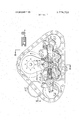
- FIG. 9 is an elevation section view of the mechanism of FIG. 8 taken along line IX-IX thereof;
- FIG. 10 is a plan section view of the mechanism of FIG. 8 taken along line X-X thereof;
- FIG. 11 is a side elevation of another crawler vehicle illustrating still another embodiment of the present invention.
- the track chain assembly 11 of the present invention may be utilized with any of the diverse known forms of crawler vehicles and accordingly only a small portion 12 of such a vehicle is shown for purposes of reference.
- a suitable vehicle of this form is disclosed, for example, in US. Pat. No. 3,435,908.
- the vehicle is usually equipped with a sidewardly projecting tubular axle housing 13 having a power drive axle 14 extending axially therefrom.
- axle housing 13 and drive axle l4 depicted in FIGS. 1 and 2 is commonly employed on certain commercially available articulated earth moving vehicles and was originally designed and is normally employed for attaching powered wheels to the vehicle.
- the track chain assembly 11 of the present invention is designed to replace such wheels without requiring any major modification of the vehicle itself including the axle housing 13 and drive axle 14.
- a main pivot shaft 15 is secured to the end of the axle housing 13 by a bracket 16 and housing 18.
- a track frame 17 is oscillatably carried on the pivot shaft and has ends which extend forwardly and rearwardly from the shaft.
- a housing 18 rotatably mounting a drive sprocket 19 which is connected to drive axle 14 through'freduction gearing 20 mounted in housing 18 adjacent the" drive sprocket.
- Front and rear idlers 22 are rotatably mounted on one end of idler support members comprising cranks 23 which are pivotally and reciprocally mounted at intermediate points on the forwardly and rearwardly ends of track frame 17 by means of trunnions 24 attached to recoil pistons 25 slidable within hydropneumatic cylinders 26 provided in the track frame ends.
- Bogi es 27 are pivotally mounted on the other ends of cranks 23.
- the bogies in turn carry pairs of track rollers 28 which support the vehicle.
- a conventional track chain 29 encompasses idlers 22, track rollers 28 and drive sprocket 19 and is maintained at a proper operating tension by the hydropneumatic cylinders 26.
- Pistons 25, pilot pistons 32 disposed within pistons 25, and cylinders 26 define a fluid chamber 35 which is filled with sufficient fluid to maintain the track chain 29 at the proper operating tension. Chambers 35 may be filled with fluid by means of conduits 36.
- cushioning of the track rollers is provided by wedgeshaped compression pads 37 disposed on the upper surfaces of the bogey-supporting ends of the cranks 23.
- the compression pads project upwardly between the cylinders 26 where they are engagable by plates 38 which are an integral part of cylinder housings 39 enclosing cylinders 26.
- each compression pad 37 comprises a resilient rubber block which tapers upwardly. Plates 38 diverge downwardly at a greater angle than the upward taper of the pads.
- the shape of compression pad 37 and plates 38 are so related that as the pads move toward the plates, they are initially engaged by the plates only at the apex of the pads.
- compression pads 37 exhibit a progressive spring rate asthey cushion upward deflection of the track roller 28.
- the spring rate of the idler recoil pistons 25 may be low.
- a relatively large object may be easily overcome by relatively unrestrained vertical displacement of the lead idler until the track rollers and bogey encounter and absorb the entire load initiated by the obstacle.
- FIG. 5 The configuration of the track suspension of the present invention during negotiation of an obstacle is illustrated in FIG. 5.
- crank 23 pivots on trunnion 24, inherently urging the bogiemounted rollers into a relatively light load area of the track. Consequently, the cycle time in which the track rollers pick-up the load encountered earlier by the track idler is shorter than in conventional track suspensions.
- crank 23 pivots on trunnion 24, returning the track rollers and idler to their original positions, at which time the rubber compression pads 37 return to engagement with plates 38, cushioning the track rollers as they pass over the obstacle.
- the forward idler and crank rotate on trunnion 24 to effect an advantageous change in the moment arm and load forces acting upon the suspension.
- the low spring rate allows the front idler and track to overcome an obstacle through a very aggressive effort of the track.
- the bridging action of the track rollers reduces substantially the load on the idler and the track rollers. In tests it has been found that this bridging action can reduce roller loads froma 37,000/87,000 pound range to a l4,000/22,000 pound range.
- FIG. 6 An alternative embodiment of an idler recoil mechanism that may be employed in the triangular track suspension of the present invention to eliminate detrimental shear and abrasive wear of the compression pads 37 is shown in FIG. 6.
- cranks 23 are rotatably mounted on slide bearings 41 which are mounted for reciprocal movement on slides 42.
- Compression pads 37, mounted on the cranks 23, are engageable by plates 38 integrally formed on the slide bearings 41. Since the plates 38' recoil with the cranks 23, the compression pads 37 will not be subject to shear forces and abrasive conditions that would otherwise be encountered when the cranks recoil.
- a single recoil cylinder 43 accommodates both the front and rear idlers. Pistons 44 disposed within the recoil cylinder have rods 45 extending therefrom which engage the slide bearings 41. Recoil cylinder 43 and pistons 44 define a chamber 46 which is filled with pressurized fluid. Chamber 46 communicates with an accumulator 52 through parallel conduits 47 and 48, having a relief valve 49 and a directional check valve 50 respectively disposed therein.
- FIG. 8 Another embodiment of the present invention is shown in FIG. 8. Idlers 22 are rotatably mounted on cranks 23' which are pivotally mounted by mean of trunnions 24'on pistons 25 slidable within hydropneumatiE' cylinders 26 provided in oscillatable track frame 17
- the cranks 23' are preloaded and cushioned by preload springs 53 connected between the cranks and brackets 54 on main pivot shaft 15.
- Suitable brackets 55 and side plates 56 forming the main structure of track frame 17', extend downwardly to permit two pairs of bogie-mounted track rollers 28 to be pivotally supported thereon.
- the hydropneumatic cylinders 26' which provide for recoiling of the idlers, have stub shafts 57 disposed coaxially therein. Hollow tubular pistons 25 are journaled for reciprocation within cylinders 26' and on stub shafts 57. Stub shafts 57 are provided with passages 58 and lines 59 for communication with a nitrogencharged accumulator 60.
- the precharge is sufficient to assure satisfactory pressure for the recoil mechanism and tension of the track.
- inter-action with the suspension and sprocket automatically results in the rear or high loaded portion of the track being under tension which consequently results in the more lightly loaded front recoil cylinder 26 exengine to the transmission, and a drive shaft 74 extending from the transmission.
- a drive sprocket 75 is rotatably mounted on the tractor frame 70 and driven by a gear 76 mounted on the end of drive shaft 74.
- a track frame 77 is pivotally mounted on the tractor frame 70 by a pivot mounting 78.
- a pivot mounting 78 In this embodiment,
- Accumulator 60 is arranged laterally within the track frame 17 so that four lines 5S connected by fittings 62 may communicate pressure through passages 58 of shafts 57 to chambers 63 serving to load recoil pistons 25' when passages 64 are covered by pistons 25'.
- the specific geometry provided the track frame and idlers in relation to the drive sprocket is such that the load vectors or reaction force of each recoil linkage is balanced within the system. Normally there is sufficient torque reaction from the driving force that a pivotally mounted track tends to walk around the sprocket or support hearing if unbalanced loading exists.
- the new mean line of force resulting from vertical oscillation and/or recoiling of the idlers falls just above the main pivot shaft 15.
- the particular arrangement of springs 53 and cranks 23' also results in parallelogram-type action that a single track frame 79 is mounted on each side of the tractor vehicle toward the rear of the vehicle.
- the for- I wardly extending end of the track frame with respect to the pivot mounting is greatly elongated, and the rearwardly extending end of the track frame is relatively short.
- Idlers 22 are rotatably mounted on one end of idler support members comprising cranks 80 and 81 respectively, which in turn are mounted on the rearwardly and forwardly extending ends of track frame 79.
- a bogie 27 is pivotally mounted on the other ends of crank 80 and 81, and has track rollers 28 rotatably mounted thereon which engage a track chain 29 encompassing idlers 22 and drive sprocket 75.
- An intermediate point of crank 80 is pivotally mounted on track frame 79.
- Crank 81 has an intermediate point pivotally mounted on a slide 41 which in turn is mounted for reciprocation on slide bearing 42' mounted on track frame 79.
- a push rod 45' is connected between slide 41 and a piston 44' disposed in a recoil cylinder 43 mounted on track frame 79 and constructed similar to recoil cylinder 43 already described.
- trailing links 82 having bogies 27' pivotally mounted thereon, are also pivotally mounted on the track frame 79.
- the bogies in turn rotatably mount track rollers 28 which engage track chain 29.
- Crank members 80 and 81 and links 82 all have resilient blocks 37' mounted thereon for engagement with plates 38' to cushion pivoting of the crank members and links when the track rollers pass over a bump.
- Blocks 37 and plates 38 are similar to blocks 37 and plates 38 previously described, exhibiting a progressive spring rate as the crank members and links pivot with respect to the track frame.
- tractor frame is resiliently supported on track frame 70 by conventional means not shown.
- Small idlers 84 and 85 rotatably mounted on tractor frame 70 maintain the track chain 29' in proper alignment between sprocket and the forward idler 22.
- a supporting and driving assembly in a vehicle having a vehicle frame and a drive shaft comprising:
- first and second idlers associated with the first and second track frame ends respectively, the first idler being movable toward and away from the second idler;
- a drive sprocket associated with said drive shaft and positioned between the ends of the trackframe and above the idlers;
- a track chain encompassing the idlers and drive sprocket and in driven engagement with the drive sprocket;
- crank member having an intermediate point pivotally secured to the first end of the track frame and having first and second legs extending from said intermediate point, with the first idler associated with the first end of the trackframe being mounted on'said first leg of the crank member;
- roller means mounted to the second leg of the crank member and in engagement with the track chain wherein said roller means mounted to the second leg comprise a bogey pivotally mounted on the second leg of the crank member, and track rollers rotatably mounted on the bogey and engaging the track chain;
- a link pivotally mounted to the track frame inwardly of the first and second idlers, and roller means mounted to the link and in engagement with the track chain.
- roller means mounted to the link comprise a bogey pivotally mounted to the link, and track rollers relatively rotatably mounted on the link bogey and engaging the track chain.
- the supporting and driving assembly in a vehicle having a vehicle frame and a drive shaft comprising:
- a track frame mounted to the vehicle frame and having forwardly and rearwardly extending ends;
- a first crank member having an intermediate point pivotally secured to the forwardlyextending end of the track frame and having first and second legs extending from said intermediate point;
- first roller means mounted on the second leg of the first crank member
- a second crank member having an intermediate point pivotally secured to the rearwardly extending end of the track frame and having first and second legs extending from said intermediate point;
- a drive sprocket associated with said drive shaft and positioned between the ends of the track frame and above the idlers;
- a track chain encompassing the first and second idlers and drive sprocket, and in driven engagement with the drive sprocket, and engaged by the first and second roller means;
- ond roller means comprise first and second bogeys pivotally mounted to the second legs of the first and second crank members respectively, and track rollers rotatably mounted to the first and second bogeys and engaging the track chain.
- third and fourth roller means comprise third and fourth bogeys pivotally mounted to the first and second links respectively, and track rollers rotatably mounted to the third and fourth bogeys and engaging the track chain.
- a supporting and driving assembly in a vehicle having a vehicle frame and a drive shaft comprising:
- first and second idlers associated with the first and second track frame ends respectively, the first idler being movable toward and away from the second idler;
- a drive sprocket associated with said drive shaft and positioned between the ends of the track frame and above the idlers;
- a track chain encompassing the idlers and drive sprocket and in driven engagement with the drive sprocket;
- crank member having an intermediate point pivotally secured to the first end of the track frame and having first and second legs extending from said intermediate point, with the first idler associated with the first end of the track frame being mounted on said first leg of the crank member;
Landscapes
- Engineering & Computer Science (AREA)
- Chemical & Material Sciences (AREA)
- Combustion & Propulsion (AREA)
- Transportation (AREA)
- Mechanical Engineering (AREA)
- Devices For Conveying Motion By Means Of Endless Flexible Members (AREA)
- Motor Power Transmission Devices (AREA)
- Soil Working Implements (AREA)
Applications Claiming Priority (1)
| Application Number | Priority Date | Filing Date | Title |
|---|---|---|---|
| US21239671A | 1971-12-27 | 1971-12-27 |
Publications (1)
| Publication Number | Publication Date |
|---|---|
| US3774708A true US3774708A (en) | 1973-11-27 |
Family
ID=22790830
Family Applications (1)
| Application Number | Title | Priority Date | Filing Date |
|---|---|---|---|
| US00212396A Expired - Lifetime US3774708A (en) | 1971-12-27 | 1971-12-27 | Triangular track resilient bogie suspension |
Country Status (5)
| Country | Link |
|---|---|
| US (1) | US3774708A (it) |
| JP (1) | JPS563832B2 (it) |
| DE (1) | DE2264015C3 (it) |
| GB (3) | GB1418646A (it) |
| IT (1) | IT974331B (it) |
Cited By (58)
| Publication number | Priority date | Publication date | Assignee | Title |
|---|---|---|---|---|
| US3938606A (en) * | 1974-11-04 | 1976-02-17 | Caterpillar Tractor Co. | Track-idler recoil suspension mechanism |
| US4227748A (en) * | 1978-05-26 | 1980-10-14 | Caterpillar Tractor Co. | Track tensioning apparatus |
| WO1981001394A1 (en) * | 1979-11-09 | 1981-05-28 | Caterpillar Tractor Co | Track tensioning apparatus |
| EP0049044A1 (en) * | 1980-08-29 | 1982-04-07 | Caterpillar Tractor Co. | Single-roller-idler assembly for a tracked undercarriage |
| US4373758A (en) * | 1981-08-10 | 1983-02-15 | Caterpillar Tractor Co. | Multiple roller bogey assembly |
| GB2155415A (en) * | 1984-03-13 | 1985-09-25 | Komatsu Mfg Co Ltd | Crawler vehicle undercarriage |
| US4647116A (en) * | 1979-06-22 | 1987-03-03 | Riggers Manufacturing Co. | Crawler suspension system |
| US4817746A (en) * | 1987-12-22 | 1989-04-04 | Caterpillar Inc. | Suspension mechanism for a track-type vehicle |
| US4874052A (en) * | 1987-12-23 | 1989-10-17 | Caterpillar Inc. | Suspension system for a vehicle |
| US4881609A (en) * | 1987-12-22 | 1989-11-21 | Caterpillar Inc. | Suspension mechanism for a track-type vehicle |
| US4953919A (en) * | 1989-02-15 | 1990-09-04 | Phoenix Engineering, Inc. | Track suspension system |
| US5316381A (en) * | 1992-11-13 | 1994-05-31 | Deere & Company | Tensioning and suspension system for a tracked vehicle |
| US5340205A (en) * | 1992-11-13 | 1994-08-23 | Deere & Company | Suspension system for a tracked vehicle |
| US5409075A (en) * | 1993-11-12 | 1995-04-25 | Nieman; Donnie L. | Pneumatic suspension system for farm equipment |
| US5452949A (en) * | 1993-12-13 | 1995-09-26 | Kelderman; Gary L. | Track system for vehicles |
| US5829848A (en) * | 1995-06-23 | 1998-11-03 | Agtracks, Inc. | Track suspension apparatus for vehicles of various types |
| US5842757A (en) * | 1997-01-31 | 1998-12-01 | Agtracks, Inc. | Track system for vehicles |
| US5899542A (en) * | 1997-02-14 | 1999-05-04 | Case Corporation | Support system for roller wheels of rubber tracked vehicle |
| US5899543A (en) * | 1997-02-14 | 1999-05-04 | Case Corporation | Resilient support element for roller wheels of a rubber tracked vehicle |
| USRE36284E (en) * | 1993-12-13 | 1999-08-31 | Agtracks, Inc. | Track system for vehicles |
| US6062661A (en) * | 1998-07-10 | 2000-05-16 | Agtracks, Inc. | Track system drive wheel for agricultural implements |
| US6062662A (en) * | 1998-07-10 | 2000-05-16 | Agtracks, Inc. | Mounting device for track apparatus |
| US6068353A (en) * | 1998-07-10 | 2000-05-30 | Agtracks, Inc. | Track apparatus incorporating non-pneumatic wheels |
| US6074024A (en) * | 1998-07-10 | 2000-06-13 | Agtracks, Inc. | Guide wheel for flexible track of a track system |
| US6074025A (en) * | 1998-07-10 | 2000-06-13 | Agtracks, Inc. | Track apparatus incorporating cantilever mounted wheels |
| US6247547B1 (en) * | 1998-04-21 | 2001-06-19 | A.S.V., Inc. | Suspension and drive mechanism for a multi-surface vehicle |
| US20030034189A1 (en) * | 2001-06-07 | 2003-02-20 | Gary Lemke | Slick track |
| USD488171S1 (en) | 2002-03-18 | 2004-04-06 | Agtracks, Inc. | Track apparatus for use in place of a vehicle wheel |
| US20050077784A1 (en) * | 2003-10-10 | 2005-04-14 | Piotr Dudzinski | Vehicle track with idler and roller suspension |
| US6945342B1 (en) * | 2003-11-03 | 2005-09-20 | Hill John D | Track drive undercarriage device, kit and method |
| US20050231035A1 (en) * | 2002-07-19 | 2005-10-20 | Giovanni Vertoni | Track-tightening device for crawlers |
| US20060181148A1 (en) * | 2005-01-28 | 2006-08-17 | Robert Bessette | Traction assembly for a vehicle |
| US20070102173A1 (en) * | 2003-12-08 | 2007-05-10 | Ati, Inc. | Soil stabilizer with track apparatus |
| US20070236085A1 (en) * | 2006-03-30 | 2007-10-11 | Satzler Ronald L | Track roller unit |
| USD563438S1 (en) * | 2004-05-24 | 2008-03-04 | Clark Equipment Company | Track for a small loader |
| US20080105472A1 (en) * | 2006-11-02 | 2008-05-08 | Tuhy Lance S | Suspension system for track vehicle |
| US20090050379A1 (en) * | 2007-08-22 | 2009-02-26 | Clark Equipment Company | Track vehicle having drive and suspension systems |
| WO2011041704A1 (en) * | 2009-10-01 | 2011-04-07 | Camoplast Inc. | Track assembly for traction of a vehicle |
| US20120023881A1 (en) * | 2010-07-30 | 2012-02-02 | Dirk Speckamp | Self-propelled harvesting machine |
| US20120080937A1 (en) * | 2009-06-08 | 2012-04-05 | Dong-Il Rubber Belt Co., Ltd. | Apparatus for Controlling Tension of Track |
| US8430188B2 (en) | 2006-12-11 | 2013-04-30 | Vermeer Manufacturing Company | Apparatus for converting a wheeled vehicle to a tracked vehicle |
| US20140008134A1 (en) * | 2007-10-03 | 2014-01-09 | Camoplast Solideal, Inc. | Track assembly for an all-terrain vehicle |
| CN103847826A (zh) * | 2013-01-28 | 2014-06-11 | 中国科学院合肥物质科学研究院 | 仿生履带式粘附行走机构及其运动方法 |
| US8801115B2 (en) | 2008-12-09 | 2014-08-12 | Vermeer Manufacturing Company | Apparatus for converting a wheeled vehicle to a tracked vehicle |
| US9033431B1 (en) | 2010-06-30 | 2015-05-19 | Camoplast Solideal Inc | Track assembly for an off-road vehicle |
| US9505454B1 (en) | 2011-06-13 | 2016-11-29 | Camso Inc. | Track assembly for traction of an off-road vehicle |
| US9643667B2 (en) | 2006-12-12 | 2017-05-09 | A.S.V., Llc | Conversion system for a wheeled vehicle |
| US10343734B2 (en) * | 2014-09-29 | 2019-07-09 | Soucy International Inc. | Track system having low vibrations |
| US10494041B2 (en) | 2015-04-29 | 2019-12-03 | Clark Equipment Company | Apparatus for mounting a track frame to a frame of a power machine |
| US10526026B2 (en) * | 2017-01-27 | 2020-01-07 | Barreto Manufacturing, Inc. | Carriage for a track drive vehicle |
| US10526027B2 (en) | 2014-09-29 | 2020-01-07 | Soucy International Inc. | Damping system for an endless track system |
| US10633044B2 (en) | 2014-09-29 | 2020-04-28 | Soucy International Inc. | Dynamic tensioner locking device for a track system and method thereof |
| US10640160B2 (en) | 2014-09-29 | 2020-05-05 | Soucy International Inc. | Progressive damping system for a track system |
| US10668962B2 (en) | 2014-09-29 | 2020-06-02 | Soucy International Inc. | Track system |
| US10875591B2 (en) | 2015-08-04 | 2020-12-29 | Camso Inc. | Track system for traction of an agricultural vehicle travelling on fields and roads |
| US11077897B2 (en) | 2015-10-23 | 2021-08-03 | Camso Manufacturing Italy S.R.L. | Track system for traction of a vehicle |
| US11485434B2 (en) * | 2019-02-27 | 2022-11-01 | Claas Selbstfahrende Erntemaschinen Gmbh | Harvester and method for harvesting using a harvester |
| CN117719407A (zh) * | 2024-02-02 | 2024-03-19 | 临汾市埠瑞联特煤机有限公司 | 气动履带升高一体运载车 |
Families Citing this family (3)
| Publication number | Priority date | Publication date | Assignee | Title |
|---|---|---|---|---|
| GB2423288B (en) * | 2005-02-19 | 2007-01-10 | Steve Heard | Track apparatus |
| JP5826589B2 (ja) * | 2011-10-21 | 2015-12-02 | ヤンマー株式会社 | 作業車両 |
| CN108575272A (zh) * | 2018-04-27 | 2018-09-28 | 王学彦 | 一种新能源农作物收割装置 |
Family Cites Families (2)
| Publication number | Priority date | Publication date | Assignee | Title |
|---|---|---|---|---|
| US3082044A (en) * | 1960-10-10 | 1963-03-19 | Massey Ferguson Inc | Endless track driving assembly |
| GB925032A (en) * | 1961-02-15 | 1963-05-01 | James Archibald Cuthbertson | Endless-track attachment for motor-propelled land vehicles |
-
1971
- 1971-12-27 US US00212396A patent/US3774708A/en not_active Expired - Lifetime
-
1972
- 1972-12-21 GB GB5920372A patent/GB1418646A/en not_active Expired
- 1972-12-21 GB GB2894475A patent/GB1418648A/en not_active Expired
- 1972-12-21 GB GB2892275A patent/GB1418647A/en not_active Expired
- 1972-12-23 DE DE2264015A patent/DE2264015C3/de not_active Expired
- 1972-12-26 JP JP12967872A patent/JPS563832B2/ja not_active Expired
- 1972-12-27 IT IT55047/72A patent/IT974331B/it active
Cited By (88)
| Publication number | Priority date | Publication date | Assignee | Title |
|---|---|---|---|---|
| US3938606A (en) * | 1974-11-04 | 1976-02-17 | Caterpillar Tractor Co. | Track-idler recoil suspension mechanism |
| US4227748A (en) * | 1978-05-26 | 1980-10-14 | Caterpillar Tractor Co. | Track tensioning apparatus |
| US4279318A (en) * | 1978-05-26 | 1981-07-21 | Caterpillar Tractor Co. | Track tensioning apparatus |
| US4647116A (en) * | 1979-06-22 | 1987-03-03 | Riggers Manufacturing Co. | Crawler suspension system |
| WO1981001394A1 (en) * | 1979-11-09 | 1981-05-28 | Caterpillar Tractor Co | Track tensioning apparatus |
| EP0049044A1 (en) * | 1980-08-29 | 1982-04-07 | Caterpillar Tractor Co. | Single-roller-idler assembly for a tracked undercarriage |
| US4373758A (en) * | 1981-08-10 | 1983-02-15 | Caterpillar Tractor Co. | Multiple roller bogey assembly |
| GB2155415A (en) * | 1984-03-13 | 1985-09-25 | Komatsu Mfg Co Ltd | Crawler vehicle undercarriage |
| FR2561609A1 (fr) * | 1984-03-13 | 1985-09-27 | Komatsu Mfg Co Ltd | Train de roulement pour vehicule a chenilles |
| AU602265B2 (en) * | 1987-12-22 | 1990-10-04 | Caterpillar Inc. | Suspension mechanism for a track-type vehicle |
| US4817746A (en) * | 1987-12-22 | 1989-04-04 | Caterpillar Inc. | Suspension mechanism for a track-type vehicle |
| US4881609A (en) * | 1987-12-22 | 1989-11-21 | Caterpillar Inc. | Suspension mechanism for a track-type vehicle |
| US4874052A (en) * | 1987-12-23 | 1989-10-17 | Caterpillar Inc. | Suspension system for a vehicle |
| US4953919A (en) * | 1989-02-15 | 1990-09-04 | Phoenix Engineering, Inc. | Track suspension system |
| US5316381A (en) * | 1992-11-13 | 1994-05-31 | Deere & Company | Tensioning and suspension system for a tracked vehicle |
| US5340205A (en) * | 1992-11-13 | 1994-08-23 | Deere & Company | Suspension system for a tracked vehicle |
| AU659760B2 (en) * | 1992-11-13 | 1995-05-25 | Deere & Company | Tensioning and suspension system for a tracked vehicle |
| AU666810B2 (en) * | 1993-06-30 | 1996-02-22 | Deere & Company | Suspension system for a tracked vehicle |
| US5409075A (en) * | 1993-11-12 | 1995-04-25 | Nieman; Donnie L. | Pneumatic suspension system for farm equipment |
| US5452949A (en) * | 1993-12-13 | 1995-09-26 | Kelderman; Gary L. | Track system for vehicles |
| USRE36284E (en) * | 1993-12-13 | 1999-08-31 | Agtracks, Inc. | Track system for vehicles |
| US5829848A (en) * | 1995-06-23 | 1998-11-03 | Agtracks, Inc. | Track suspension apparatus for vehicles of various types |
| US5842757A (en) * | 1997-01-31 | 1998-12-01 | Agtracks, Inc. | Track system for vehicles |
| US5899543A (en) * | 1997-02-14 | 1999-05-04 | Case Corporation | Resilient support element for roller wheels of a rubber tracked vehicle |
| US5899542A (en) * | 1997-02-14 | 1999-05-04 | Case Corporation | Support system for roller wheels of rubber tracked vehicle |
| US6247547B1 (en) * | 1998-04-21 | 2001-06-19 | A.S.V., Inc. | Suspension and drive mechanism for a multi-surface vehicle |
| US7188915B2 (en) | 1998-04-21 | 2007-03-13 | A.S.V., Inc. | Suspension and drive mechanism for a multi-surface vehicle |
| US6497460B2 (en) | 1998-04-21 | 2002-12-24 | A. S. V., Inc. | Suspension and drive mechanism for a multi-surface vehicle |
| US6435292B2 (en) | 1998-04-21 | 2002-08-20 | A.S.V., Inc. | Suspension and drive mechanism for a multi-surface vehicle |
| US6435291B2 (en) | 1998-04-21 | 2002-08-20 | A.S.V., Inc. | Suspension and drive mechanism for multi-surface vehicle |
| US6068353A (en) * | 1998-07-10 | 2000-05-30 | Agtracks, Inc. | Track apparatus incorporating non-pneumatic wheels |
| US6074025A (en) * | 1998-07-10 | 2000-06-13 | Agtracks, Inc. | Track apparatus incorporating cantilever mounted wheels |
| US6074024A (en) * | 1998-07-10 | 2000-06-13 | Agtracks, Inc. | Guide wheel for flexible track of a track system |
| US6062662A (en) * | 1998-07-10 | 2000-05-16 | Agtracks, Inc. | Mounting device for track apparatus |
| US6062661A (en) * | 1998-07-10 | 2000-05-16 | Agtracks, Inc. | Track system drive wheel for agricultural implements |
| US20030034189A1 (en) * | 2001-06-07 | 2003-02-20 | Gary Lemke | Slick track |
| USD488171S1 (en) | 2002-03-18 | 2004-04-06 | Agtracks, Inc. | Track apparatus for use in place of a vehicle wheel |
| US20050231035A1 (en) * | 2002-07-19 | 2005-10-20 | Giovanni Vertoni | Track-tightening device for crawlers |
| US7467831B2 (en) * | 2002-07-19 | 2008-12-23 | Berco S.P.A | Track-tightening device for crawlers |
| US20050077784A1 (en) * | 2003-10-10 | 2005-04-14 | Piotr Dudzinski | Vehicle track with idler and roller suspension |
| US6945342B1 (en) * | 2003-11-03 | 2005-09-20 | Hill John D | Track drive undercarriage device, kit and method |
| US8291993B2 (en) * | 2003-12-08 | 2012-10-23 | Ati, Inc. | Soil stabilizer with track apparatus |
| US20070102173A1 (en) * | 2003-12-08 | 2007-05-10 | Ati, Inc. | Soil stabilizer with track apparatus |
| USD563438S1 (en) * | 2004-05-24 | 2008-03-04 | Clark Equipment Company | Track for a small loader |
| US7497530B2 (en) * | 2005-01-28 | 2009-03-03 | Soucy International Inc. | Traction assembly for a vehicle |
| US20060181148A1 (en) * | 2005-01-28 | 2006-08-17 | Robert Bessette | Traction assembly for a vehicle |
| US20070236085A1 (en) * | 2006-03-30 | 2007-10-11 | Satzler Ronald L | Track roller unit |
| US7628235B2 (en) * | 2006-03-30 | 2009-12-08 | Claas Industrietechnik Gmbh | Track roller unit |
| US7552785B2 (en) | 2006-11-02 | 2009-06-30 | Clark Equipment Company | Suspension system for track vehicle |
| US20080105472A1 (en) * | 2006-11-02 | 2008-05-08 | Tuhy Lance S | Suspension system for track vehicle |
| US8430188B2 (en) | 2006-12-11 | 2013-04-30 | Vermeer Manufacturing Company | Apparatus for converting a wheeled vehicle to a tracked vehicle |
| US9352776B2 (en) | 2006-12-11 | 2016-05-31 | Vermeer Manufacturing Company | Apparatus for converting a wheeled vehicle to a tracked vehicle |
| US9180910B2 (en) | 2006-12-11 | 2015-11-10 | Vermeer Manufacturing Company | Apparatus for converting a wheeled vehicle to a tracked vehicle |
| US9079614B2 (en) | 2006-12-11 | 2015-07-14 | Vermeer Manufacturing Company | Apparatus for converting a wheeled vehicle to a tracked vehicle |
| US8827013B2 (en) | 2006-12-11 | 2014-09-09 | Vermeer Manufacturing Company | Apparatus for converting a wheeled vehicle to a tracked vehicle |
| US9643667B2 (en) | 2006-12-12 | 2017-05-09 | A.S.V., Llc | Conversion system for a wheeled vehicle |
| US7798260B2 (en) | 2007-08-22 | 2010-09-21 | Clark Equipment Company | Track vehicle having drive and suspension systems |
| US20090050379A1 (en) * | 2007-08-22 | 2009-02-26 | Clark Equipment Company | Track vehicle having drive and suspension systems |
| US20140008134A1 (en) * | 2007-10-03 | 2014-01-09 | Camoplast Solideal, Inc. | Track assembly for an all-terrain vehicle |
| US10005507B2 (en) * | 2007-10-03 | 2018-06-26 | Camso Inc. | Track assembly for an all-terrain vehicle |
| US8801115B2 (en) | 2008-12-09 | 2014-08-12 | Vermeer Manufacturing Company | Apparatus for converting a wheeled vehicle to a tracked vehicle |
| US20120080937A1 (en) * | 2009-06-08 | 2012-04-05 | Dong-Il Rubber Belt Co., Ltd. | Apparatus for Controlling Tension of Track |
| US8733850B2 (en) * | 2009-06-08 | 2014-05-27 | Dong-Il Rubber Belt Co., Ltd. | Apparatus for controlling tension of track |
| WO2011041704A1 (en) * | 2009-10-01 | 2011-04-07 | Camoplast Inc. | Track assembly for traction of a vehicle |
| US9033431B1 (en) | 2010-06-30 | 2015-05-19 | Camoplast Solideal Inc | Track assembly for an off-road vehicle |
| US8341926B2 (en) * | 2010-07-30 | 2013-01-01 | Claas Selbstfahrende Erntemaschinen Gmbh | Self-propelled harvesting machine with hydropneumatic dampening system |
| US20120023881A1 (en) * | 2010-07-30 | 2012-02-02 | Dirk Speckamp | Self-propelled harvesting machine |
| US10399619B1 (en) | 2011-06-13 | 2019-09-03 | Camso Inc. | Track assembly for traction of an off-road vehicle |
| US9505454B1 (en) | 2011-06-13 | 2016-11-29 | Camso Inc. | Track assembly for traction of an off-road vehicle |
| US11661125B2 (en) | 2011-06-13 | 2023-05-30 | Camso Inc. | Track assembly for traction of an off-road vehicle |
| US10112663B1 (en) | 2011-06-13 | 2018-10-30 | Camso Inc. | Track assembly for traction of an off-road vehicle |
| CN103847826B (zh) * | 2013-01-28 | 2016-07-06 | 中国科学院合肥物质科学研究院 | 仿生履带式粘附行走机构及其运动方法 |
| CN103847826A (zh) * | 2013-01-28 | 2014-06-11 | 中国科学院合肥物质科学研究院 | 仿生履带式粘附行走机构及其运动方法 |
| US11286013B2 (en) | 2014-09-29 | 2022-03-29 | Soucy International Inc. | Dynamic tensioner locking device for a track system and method thereof |
| US10526027B2 (en) | 2014-09-29 | 2020-01-07 | Soucy International Inc. | Damping system for an endless track system |
| US10633044B2 (en) | 2014-09-29 | 2020-04-28 | Soucy International Inc. | Dynamic tensioner locking device for a track system and method thereof |
| US10640162B2 (en) | 2014-09-29 | 2020-05-05 | Soucy International Inc. | Tensioning system for an endless track system |
| US10640160B2 (en) | 2014-09-29 | 2020-05-05 | Soucy International Inc. | Progressive damping system for a track system |
| US10668962B2 (en) | 2014-09-29 | 2020-06-02 | Soucy International Inc. | Track system |
| US10343734B2 (en) * | 2014-09-29 | 2019-07-09 | Soucy International Inc. | Track system having low vibrations |
| US10494041B2 (en) | 2015-04-29 | 2019-12-03 | Clark Equipment Company | Apparatus for mounting a track frame to a frame of a power machine |
| US10875591B2 (en) | 2015-08-04 | 2020-12-29 | Camso Inc. | Track system for traction of an agricultural vehicle travelling on fields and roads |
| US11077897B2 (en) | 2015-10-23 | 2021-08-03 | Camso Manufacturing Italy S.R.L. | Track system for traction of a vehicle |
| US11524731B2 (en) | 2017-01-27 | 2022-12-13 | Barreto Manufacturing, Inc. | Carriage for a track drive vehicle |
| US10526026B2 (en) * | 2017-01-27 | 2020-01-07 | Barreto Manufacturing, Inc. | Carriage for a track drive vehicle |
| US11485434B2 (en) * | 2019-02-27 | 2022-11-01 | Claas Selbstfahrende Erntemaschinen Gmbh | Harvester and method for harvesting using a harvester |
| CN117719407A (zh) * | 2024-02-02 | 2024-03-19 | 临汾市埠瑞联特煤机有限公司 | 气动履带升高一体运载车 |
| CN117719407B (zh) * | 2024-02-02 | 2024-04-12 | 临汾市埠瑞联特煤机有限公司 | 气动履带升高一体运载车 |
Also Published As
| Publication number | Publication date |
|---|---|
| JPS4876229A (it) | 1973-10-13 |
| DE2264015C3 (de) | 1982-02-25 |
| JPS563832B2 (it) | 1981-01-27 |
| IT974331B (it) | 1974-06-20 |
| DE2264015A1 (de) | 1973-07-05 |
| DE2264015B2 (de) | 1981-05-27 |
| GB1418648A (en) | 1975-12-24 |
| GB1418646A (en) | 1975-12-24 |
| GB1418647A (en) | 1975-12-24 |
Similar Documents
| Publication | Publication Date | Title |
|---|---|---|
| US3774708A (en) | Triangular track resilient bogie suspension | |
| US3841424A (en) | Triangular track resilient bogie suspension | |
| US6810975B2 (en) | Suspension system for a tracked vehicle | |
| US9434426B2 (en) | Track suspension | |
| EP0049044B1 (en) | Single-roller-idler assembly for a tracked undercarriage | |
| US8499877B1 (en) | Suspension architecture for a snowmobile | |
| US7467831B2 (en) | Track-tightening device for crawlers | |
| US4572311A (en) | Walking beam arrangement for adverse terrain vehicle | |
| US4053171A (en) | Spring suspension arrangement for off-road vehicles | |
| JPS6132193B2 (it) | ||
| WO1983002596A1 (en) | Recoil system for track-type vehicles | |
| US2612387A (en) | Vehicle wheel compensating suspension | |
| US4582153A (en) | Suspension assembly for track-type vehicle | |
| US20050077784A1 (en) | Vehicle track with idler and roller suspension | |
| RU142289U1 (ru) | Подвеска рулевой лыжи снегохода | |
| CN117681981A (zh) | 一种用于拖拉机的橡胶履带结构 | |
| US3554574A (en) | Arrangement in the suspension system of traction vehicles for semitrailers | |
| US3464511A (en) | Hydropneumatic suspension system | |
| US3724587A (en) | Suspension for pivotal track frames on terrain motor vehicles | |
| AU2003241626B2 (en) | A suspension system for a tracked vehicle | |
| CN221710406U (zh) | 一种小型山地拖拉机悬挂自适应地形平衡机构 | |
| CN221114141U (zh) | 一种用于拖拉机的橡胶履带结构 | |
| RU2059502C1 (ru) | Горная двухгусеничная машина | |
| US4070037A (en) | Suspension for vehicles |
Legal Events
| Date | Code | Title | Description |
|---|---|---|---|
| AS | Assignment |
Owner name: CATERPILLAR INC., A CORP. OF DE.,ILLINOIS Free format text: ASSIGNMENT OF ASSIGNORS INTEREST;ASSIGNOR:CATERPILLAR TRACTOR CO., A CORP. OF CALIF.;REEL/FRAME:004669/0905 Effective date: 19860515 Owner name: CATERPILLAR INC., 100 N.E. ADAMS STREET, PEORIA, I Free format text: ASSIGNMENT OF ASSIGNORS INTEREST.;ASSIGNOR:CATERPILLAR TRACTOR CO., A CORP. OF CALIF.;REEL/FRAME:004669/0905 Effective date: 19860515 |