US3772637A - Device for sealing electrical connectors - Google Patents
Device for sealing electrical connectors Download PDFInfo
- Publication number
- US3772637A US3772637A US00226689A US3772637DA US3772637A US 3772637 A US3772637 A US 3772637A US 00226689 A US00226689 A US 00226689A US 3772637D A US3772637D A US 3772637DA US 3772637 A US3772637 A US 3772637A
- Authority
- US
- United States
- Prior art keywords
- flange
- openings
- cavities
- pressure plate
- plate member
- Prior art date
- Legal status (The legal status is an assumption and is not a legal conclusion. Google has not performed a legal analysis and makes no representation as to the accuracy of the status listed.)
- Expired - Lifetime
Links
Images
Classifications
-
- B—PERFORMING OPERATIONS; TRANSPORTING
- B25—HAND TOOLS; PORTABLE POWER-DRIVEN TOOLS; MANIPULATORS
- B25B—TOOLS OR BENCH DEVICES NOT OTHERWISE PROVIDED FOR, FOR FASTENING, CONNECTING, DISENGAGING, OR HOLDING
- B25B27/00—Hand tools, specially adapted for fitting together or separating parts or objects whether or not involving some deformation, not otherwise provided for
- B25B27/02—Hand tools, specially adapted for fitting together or separating parts or objects whether or not involving some deformation, not otherwise provided for for connecting objects by press fit or detaching same
-
- B—PERFORMING OPERATIONS; TRANSPORTING
- B25—HAND TOOLS; PORTABLE POWER-DRIVEN TOOLS; MANIPULATORS
- B25B—TOOLS OR BENCH DEVICES NOT OTHERWISE PROVIDED FOR, FOR FASTENING, CONNECTING, DISENGAGING, OR HOLDING
- B25B7/00—Pliers; Other hand-held gripping tools with jaws on pivoted limbs; Details applicable generally to pivoted-limb hand tools
-
- H—ELECTRICITY
- H01—ELECTRIC ELEMENTS
- H01R—ELECTRICALLY-CONDUCTIVE CONNECTIONS; STRUCTURAL ASSOCIATIONS OF A PLURALITY OF MUTUALLY-INSULATED ELECTRICAL CONNECTING ELEMENTS; COUPLING DEVICES; CURRENT COLLECTORS
- H01R13/00—Details of coupling devices of the kinds covered by groups H01R12/70 or H01R24/00 - H01R33/00
- H01R13/46—Bases; Cases
- H01R13/52—Dustproof, splashproof, drip-proof, waterproof, or flameproof cases
- H01R13/5205—Sealing means between cable and housing, e.g. grommet
- H01R13/5208—Sealing means between cable and housing, e.g. grommet having at least two cable receiving openings
-
- Y—GENERAL TAGGING OF NEW TECHNOLOGICAL DEVELOPMENTS; GENERAL TAGGING OF CROSS-SECTIONAL TECHNOLOGIES SPANNING OVER SEVERAL SECTIONS OF THE IPC; TECHNICAL SUBJECTS COVERED BY FORMER USPC CROSS-REFERENCE ART COLLECTIONS [XRACs] AND DIGESTS
- Y10—TECHNICAL SUBJECTS COVERED BY FORMER USPC
- Y10S—TECHNICAL SUBJECTS COVERED BY FORMER USPC CROSS-REFERENCE ART COLLECTIONS [XRACs] AND DIGESTS
- Y10S277/00—Seal for a joint or juncture
- Y10S277/924—Deformation, material removal, or molding for manufacture of seal
-
- Y—GENERAL TAGGING OF NEW TECHNOLOGICAL DEVELOPMENTS; GENERAL TAGGING OF CROSS-SECTIONAL TECHNOLOGIES SPANNING OVER SEVERAL SECTIONS OF THE IPC; TECHNICAL SUBJECTS COVERED BY FORMER USPC CROSS-REFERENCE ART COLLECTIONS [XRACs] AND DIGESTS
- Y10—TECHNICAL SUBJECTS COVERED BY FORMER USPC
- Y10S—TECHNICAL SUBJECTS COVERED BY FORMER USPC CROSS-REFERENCE ART COLLECTIONS [XRACs] AND DIGESTS
- Y10S439/00—Electrical connectors
- Y10S439/933—Special insulation
- Y10S439/936—Potting material or coating, e.g. grease, insulative coating, sealant or, adhesive
-
- Y—GENERAL TAGGING OF NEW TECHNOLOGICAL DEVELOPMENTS; GENERAL TAGGING OF CROSS-SECTIONAL TECHNOLOGIES SPANNING OVER SEVERAL SECTIONS OF THE IPC; TECHNICAL SUBJECTS COVERED BY FORMER USPC CROSS-REFERENCE ART COLLECTIONS [XRACs] AND DIGESTS
- Y10—TECHNICAL SUBJECTS COVERED BY FORMER USPC
- Y10T—TECHNICAL SUBJECTS COVERED BY FORMER US CLASSIFICATION
- Y10T29/00—Metal working
- Y10T29/53—Means to assemble or disassemble
- Y10T29/53796—Puller or pusher means, contained force multiplying operator
- Y10T29/53896—Puller or pusher means, contained force multiplying operator having lever operator
- Y10T29/539—Plier type means
Definitions
- ABSTRACT This invention relates to a device and method for sealing openings such as found on the rear faces of electrical connectors from which a number of electrical leads emanate. More particularly, the invention relates to a layer of scalable material attached to a rigid member to form a disk which can be pressed into a recess in the rear face of a connector, the pressure causing the material to flow into passageways and openings and sealing the electrical leads therein.
- Circular electrical connectors have one or more electrical terminal contacts, crimped or otherwise fastened onto electrical conductors, retained therein.
- the terminal contacts are inserted into suitable passageways in the connector from the rear face and extend therethrough to a mating face where they may be electrically connected with mateable terminal contacts retained in another connector.
- the rear faces of such connectors are often exposed and require some form of sealing.
- Prior art discloses various means for waterproofing or otherwise protecting the rear face of the circular connectors.
- the most prevalent means includes a resilient grommet, generally made from neoprene or silicone rubber, which fits over the rear face and is bonded to the connector.
- the grommet contains a plurality of openings to accommodate the emanating electrical leads.
- the grommet is first slipped over the rear end of the connector and bonded thereto.
- the terminal contacts and attached conductors are then pushed thru the openings in the grommet and into the passageways in the connector. Sealing of the conductors takes place via glands positioned in each of the several openings in the grommet.
- extreme care must be exercised when pushing the terminal contact through the grommet so the walls defining the openings will not be torn, or ripped. For this reason, expensive screw-machine terminal contacts having hooded contact tines are almost exclusively used with such grommets.
- Another commonly used technique for sealing the rear faces of circular connectors is that of potting.
- a flowable material such as an epoxy resin
- the material sets, either by applying heat or other commonly known setting means, forming a rigid, impervious seal. While the potting technique produces a satisfactory seal, it is time consuming, complex to applyand messy.
- the present invention provides a sealing device consisting of a disk having one layer of an impervious, sealing material capable of flowing under pressure and retaining such shape impressed thereon by such pressure, and a second member of rigid material operable to transfer pressure applied thereto to the layer of sealing material causing such to flow into and seal openings and passageways adjacent to the layer of sealing material.
- FIG. 5 shows the preferred embodiment of the present invention in position prior to being attached to the rear face of the electrical connector of FIG. 1;
- FIG. 6 shows the preferred embodiment of the present invention after being applied to the electrical connector of FIG. 5.
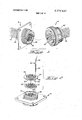
- FIG. 1 a pair of mateable electrical connectors of the type used herein to describe the present invention is shown. On the left is connector 12 and on the right is connector 14, the latter adapted to telescopingly mate with the former as is well known in the art.
- the bodies 16 (see FIG. 3) of connector 12 connector 14 are solid with a number of passageways 18 therethrough adapted to house a plurality of terminal contacts 22. These contacts can be of the pin type seen emerging from mating face 20 in connector 12 or of the socket type which is represented by circles on mating face 20 on connector 14.
- Electrical conductors 24, crimped or otherwise fastened to one or other type of terminal contact 22 as seen in FIG. 2, can be seen emerging from faces 26 26 of connector 12 and connector 14 respectively.
- the combination of terminal contact 22 and electrical conductor 24 is hereinafter referred to as lead 25.
- FIG. 2 shows in exploded fashion the rear face 26 of connector 12 and a recess 28 therein.
- a sealing member 30 which is normally affixed to the bottom side 32 of rearward face cover and pressure plate 34 to form a sealing disk 35.
- Sealing member 30 is fabricated from butyl rubber or other like sticky material having the property of being able to flow under modest pressure and to hold the shape impressed upon it after pressure is released therefrom.
- Pressure plate 34 has an annular flange 36 and a skirt 37, the former having a diameter at least equal to that of rearward face 26 as can be seen in FIG. 3, and the latter having a diametr equal to that of recess 28.
- Plate 34 is made from a rigid material such as a glass-filled nylon. Both member 30 and plate 34 have openings 38 and 39, respectively, which can be aligned with passageways 18 in connector 12 connector 14 is seen in FIGS. 2, 3, 5 and 6.
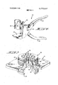
- FIG. 3 shows the positioning of sealing disk 35 into recess 28 in rear face 26 of connector 12 before pressure is applied thereto. For reasons of clarity, leads 25 have been omitted.
- FIG. 4 illustrates one embodiment of a tool 40 suitable for applying pressure to the assembly shown in FIG. 3.
- the tool consists of a pair of arms 41, 42 pivotally connected at pin 44. Arm 41 terminates in plate 46 and arm 42 terminates in a cylinder 48 which has a longitudinal slot 50 shaped like a funnel.
- Tool 40 shows a rack at 52, which cooperates with a gear (not shown) on arm 42 so that the space between plate 46 and cylinder 48 can be adjusted.
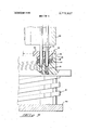
- FIG. shows the aforementioned assembly placed on plate 46 of tool 40. Leads 25 have been fed through cylinder 48 via slot 50, the cone portion of the funnel shaped slot facilitating that process.
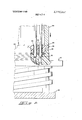
- Cylinder 48 is now brought to bear down on sealing disk 35 as seen in FIG. 6. This pressure, transferred from plate 34, causes the sealing member 30 to extrude or flow into and fill up openings 39 in pressure plate 34 and into passageways 18 in connector 12. At the same time, pressure plate 34 is being wedged into recess 28. Tool 40 may now be removed from the connector whose rearward face 26 is sealed against water, dust and other contaminents.
- the present invention provides a simple device and means for sealing a surface.
- the device is suited for an unbroken surface, its novelty makes it well adapted to uneven surfaces where the sealing layer can flow into pits, openings, cracks and so forth.
- the device is extremely well adapted to sealing electrical connectors as shown and described above.
- the present invention is insensitive to and unaffected by tears and rips which may be imaprted to the walls of the openings in the disk as terminal contacts are pushed through.
- the device is very simple to assemble and does not require post-assembly bonding, heating or chemical treating.
- Yet another advantage of the present invention is that it is non-contaminating and safe to handle and use.
- a multi-contact electrical connector housing said housing being adapted to receive electrical contact terminals which are crimped onto wires, said housing comprising:
- a molded block of hard plastic insulating material said block having a mating face and a rearward face
- a sealing member of flowable material in said enclosure against said rearward face said sealing member having a thickness which is less than the height of said flange whereby said sealing member is received from the edge of said flange, said sealing 5 member having first openings therein in alignment with said cavities, and a pressure plate member in said enclosure, said pressure plate member fitting snugly within said enclosure and having a radially extending flange, said flange being spaced from said edge, said pressure plate member being of a hard plastic material and having second openings therein which are in alignment with said first openings and said cavities whereby, upon inserting said terminals through said openings and into said cavities and thereafter pressing said pressure plate member into said enclosure until said radially extending flange is seated against said edge of said axial flange, said sealing member is compressed and caused to flow into said second openings and into said cavities, and circumferential seals are thereby formed around said terminals.
- a sealed multi-contact electrical connector comprising:
- a generally cylindrical insulating housing said housing being of a hard plastic material and having a mating face and a rearward face, a plurality of cavities extending through said housing from said rearward face to said mating face, an axially extending circular flange extending from said rearward face, said flange defining an enclosure surrounding said 35 cavities.
- a pressure plate member in said enclosure said pressure plate member comprising a disc snugly fitted within said enclosure, said disc being spaced from said rearward face and having a radially extending flange, said radially extending flange being against the edge of said circular flange, said pressure plate member having a plurality of openings therein in alignment with said cavities,
- an electrical contact terminal having a wire secured thereto in each of said cavities, said wires extending through said openings, and a compressed matrix of sealing material between said rearward face and said pressure plate member, said sealing material being extruded through said openings and onto external surface portions of said pressure plate member, said sealing material forming a seal around said wires and terminals.
Landscapes
- Engineering & Computer Science (AREA)
- Mechanical Engineering (AREA)
- Connector Housings Or Holding Contact Members (AREA)
Abstract
This invention relates to a device and method for sealing openings such as found on the rear faces of electrical connectors from which a number of electrical leads emanate. More particularly, the invention relates to a layer of sealable material attached to a rigid member to form a disk which can be pressed into a recess in the rear face of a connector, the pressure causing the material to flow into passageways and openings and sealing the electrical leads therein.
Description
United States Patent [191 Paullus et a1.
[ 1 Nov. 13, 1973 1 DEVICE FOR SEALING ELECTRICAL CONNECTORS [75] Inventors: Clarence Leonard Paullus,
Lewisberry; Larry Ronald Stauffer, Camp Hill, both of Pa.
[73] Assignee: AMP Incorporated, Harrisburg, Pa. [22] Filed: Feb. 16, 1972 [211 App]. No.: 226,689
[52] US. Cl. 339/102 R, 29/268, 8l/5.l R,
81/418, 174/76, 174/77 R, 277/12, 339/89 M [51] Int. Cl H01! 13/52, B25b 27/02 [58] Field of Search 174/20, 22 R, 23 R,
174/65 SS, 76, 77 R, 151; 277/12, 125, 227, 233; 339/60 M, 89 M, 94 R, 94 M, 218 R,
[56] References Cited UNITED STATES PATENTS 2,443,654 6/1948 Else et al 339/60 M 2,621,228 12/1952 Tompers 174/22 R UX 2,700,140 1/1955 Phillips 174/77 R X 3,151,209 9/1964 D'Ascoli ct n1. 174/77 R X 3,504,099 3/1970 Beinhaur 174/76 X 3,555,171 1/1971 Larson 174/77 R X FOREIGN PATENTS OR APPLICATIONS 589,697 6/1947 Great Britain 174/151 1,215,893 11/1959 France 339/89 M 885,191 12/1961 Great Britain 174/151 958,528 5/1964 Great Britain 174/151 Primary ExaminerLaramie E. Askin Attorney-William J. Keating et a1.
[57] ABSTRACT This invention relates to a device and method for sealing openings such as found on the rear faces of electrical connectors from which a number of electrical leads emanate. More particularly, the invention relates to a layer of scalable material attached to a rigid member to form a disk which can be pressed into a recess in the rear face of a connector, the pressure causing the material to flow into passageways and openings and sealing the electrical leads therein.
3 Claims, 6 Drawing Figures PATENTEU HEY I 3 I975 3.772.637 sum 10F 4 I PAIENIEnnnv 13 Ian $772,637
sum 30F 4 PAIENTEDNUV 13 ms I S; 772.637
sum m 4 l 39 I 30 I x 26 J X I i 2. w :22; 1
DEVICE FOR SEALING ELECTRICAL CONNECTORS BACKGROUND OF THE INVENTION Circular electrical connectors have one or more electrical terminal contacts, crimped or otherwise fastened onto electrical conductors, retained therein. The terminal contacts are inserted into suitable passageways in the connector from the rear face and extend therethrough to a mating face where they may be electrically connected with mateable terminal contacts retained in another connector. The rear faces of such connectors are often exposed and require some form of sealing. Prior art discloses various means for waterproofing or otherwise protecting the rear face of the circular connectors. The most prevalent means includes a resilient grommet, generally made from neoprene or silicone rubber, which fits over the rear face and is bonded to the connector. The grommet contains a plurality of openings to accommodate the emanating electrical leads. The grommet is first slipped over the rear end of the connector and bonded thereto. The terminal contacts and attached conductors are then pushed thru the openings in the grommet and into the passageways in the connector. Sealing of the conductors takes place via glands positioned in each of the several openings in the grommet. As is well known in the art, extreme care must be exercised when pushing the terminal contact through the grommet so the walls defining the openings will not be torn, or ripped. For this reason, expensive screw-machine terminal contacts having hooded contact tines are almost exclusively used with such grommets.
Another commonly used technique for sealing the rear faces of circular connectors is that of potting. A flowable material, such as an epoxy resin, is poured into a recess in the rear face of an electrical connector wherein the terminal contacts with electrical conductors attached thereto have already been inserted. The material sets, either by applying heat or other commonly known setting means, forming a rigid, impervious seal. While the potting technique produces a satisfactory seal, it is time consuming, complex to applyand messy.
Accordingly, the present invention provides a sealing device consisting of a disk having one layer of an impervious, sealing material capable of flowing under pressure and retaining such shape impressed thereon by such pressure, and a second member of rigid material operable to transfer pressure applied thereto to the layer of sealing material causing such to flow into and seal openings and passageways adjacent to the layer of sealing material.
BRIEF DESCRIPTION OF THE DRAWINGS FIG. 5 shows the preferred embodiment of the present invention in position prior to being attached to the rear face of the electrical connector of FIG. 1; and
FIG. 6 shows the preferred embodiment of the present invention after being applied to the electrical connector of FIG. 5.
DESCRIPTION OF THE PREFERRED EMBODIMENT In FIG. 1 a pair of mateable electrical connectors of the type used herein to describe the present invention is shown. On the left is connector 12 and on the right is connector 14, the latter adapted to telescopingly mate with the former as is well known in the art. The bodies 16 (see FIG. 3) of connector 12 connector 14 are solid with a number of passageways 18 therethrough adapted to house a plurality of terminal contacts 22. These contacts can be of the pin type seen emerging from mating face 20 in connector 12 or of the socket type which is represented by circles on mating face 20 on connector 14. Electrical conductors 24, crimped or otherwise fastened to one or other type of terminal contact 22 as seen in FIG. 2, can be seen emerging from faces 26 26 of connector 12 and connector 14 respectively. The combination of terminal contact 22 and electrical conductor 24 .is hereinafter referred to as lead 25.
FIG. 2 shows in exploded fashion the rear face 26 of connector 12 and a recess 28 therein. Directly above connector 12 is a sealing member 30 which is normally affixed to the bottom side 32 of rearward face cover and pressure plate 34 to form a sealing disk 35. Sealing member 30 is fabricated from butyl rubber or other like sticky material having the property of being able to flow under modest pressure and to hold the shape impressed upon it after pressure is released therefrom.
Above pressure plate 34 and shown being aligned with one of the openings 38 39 and passageway 18 is lead 25.
FIG. 3 shows the positioning of sealing disk 35 into recess 28 in rear face 26 of connector 12 before pressure is applied thereto. For reasons of clarity, leads 25 have been omitted.
FIG. 4 illustrates one embodiment of a tool 40 suitable for applying pressure to the assembly shown in FIG. 3. The tool consists of a pair of arms 41, 42 pivotally connected at pin 44. Arm 41 terminates in plate 46 and arm 42 terminates in a cylinder 48 which has a longitudinal slot 50 shaped like a funnel. Tool 40 shows a rack at 52, which cooperates with a gear (not shown) on arm 42 so that the space between plate 46 and cylinder 48 can be adjusted.
UTILIZATION OF THE PREFERRED EMBODIMENT In the utilization of sealing disk 35, the disk is placed partly into recess 28 manually. Leads 25 are then threaded through openings 38 and 39 in disk 35 and pushed into passageways 18 in connector 12 (or connector 14 as the case may be). FIG. shows the aforementioned assembly placed on plate 46 of tool 40. Leads 25 have been fed through cylinder 48 via slot 50, the cone portion of the funnel shaped slot facilitating that process.
As is now apparent, the present invention provides a simple device and means for sealing a surface. Although the device is suited for an unbroken surface, its novelty makes it well adapted to uneven surfaces where the sealing layer can flow into pits, openings, cracks and so forth. Quite obviously the device is extremely well adapted to sealing electrical connectors as shown and described above. And as is also apparent, the present invention is insensitive to and unaffected by tears and rips which may be imaprted to the walls of the openings in the disk as terminal contacts are pushed through. Further, the device is very simple to assemble and does not require post-assembly bonding, heating or chemical treating. Yet another advantage of the present invention is that it is non-contaminating and safe to handle and use.
Although the invention has been described with reference to the embodiment illustrated, it will be appreciated by those skilled in the art that additions, modifications, substitutions, deletions and other changes not specifically described may be made which fall within the spirit of the invention as defined in the following claims.
What is claimed is:
1. A multi-contact electrical connector housing, said housing being adapted to receive electrical contact terminals which are crimped onto wires, said housing comprising:
a molded block of hard plastic insulating material, said block having a mating face and a rearward face,
a plurality of contact-receiving cavities extending through said block from said rearward face to said mating face, an axial flange extending around the periphery of said rearward face, said flange defining an enclosure extending continuously around said cavities,
a sealing member of flowable material in said enclosure against said rearward face, said sealing member having a thickness which is less than the height of said flange whereby said sealing member is received from the edge of said flange, said sealing 5 member having first openings therein in alignment with said cavities, and a pressure plate member in said enclosure, said pressure plate member fitting snugly within said enclosure and having a radially extending flange, said flange being spaced from said edge, said pressure plate member being of a hard plastic material and having second openings therein which are in alignment with said first openings and said cavities whereby, upon inserting said terminals through said openings and into said cavities and thereafter pressing said pressure plate member into said enclosure until said radially extending flange is seated against said edge of said axial flange, said sealing member is compressed and caused to flow into said second openings and into said cavities, and circumferential seals are thereby formed around said terminals. 2. A connector housing as set forth in claim 1, said connector housing being cylindrical.
3. A sealed multi-contact electrical connector, said connector comprising:
a generally cylindrical insulating housing, said housing being of a hard plastic material and having a mating face and a rearward face, a plurality of cavities extending through said housing from said rearward face to said mating face, an axially extending circular flange extending from said rearward face, said flange defining an enclosure surrounding said 35 cavities.
a pressure plate member in said enclosure, said pressure plate member comprising a disc snugly fitted within said enclosure, said disc being spaced from said rearward face and having a radially extending flange, said radially extending flange being against the edge of said circular flange, said pressure plate member having a plurality of openings therein in alignment with said cavities,
an electrical contact terminal having a wire secured thereto in each of said cavities, said wires extending through said openings, and a compressed matrix of sealing material between said rearward face and said pressure plate member, said sealing material being extruded through said openings and onto external surface portions of said pressure plate member, said sealing material forming a seal around said wires and terminals.
Claims (3)
1. A multi-contact electrical connector housing, said housing being adapted to receive electrical contact terminals which are crimped onto wires, said housing comprising: a molded block of hard plastic insulating material, said block having a mating face and a rearward face, a plurality of contact-receiving cavities extending through said block from said rearward face to said mating face, an axial flange extending around the periphery of said rearward face, said flange defining an enclosure extending continuously around said cavities, a sealing member of flowable material in said enclosure against said rearward face, said sealing member having a thickness which is less than the height of said flange whereby said sealing member is received from the edge of said flange, said sealing member having first openings therein in alignment with said cavities, and a pressure plate member in said enclosure, said pressure plate member fitting snugly within said enclosure and having a radially extending flange, said flange being spaced from said edge, said pressure plate member being of a hard plastic material and having second openings therein which are in alignment with said first openings and said cavities whereby, upon inserting said terminals through said openings and into said cavities and thereafter pressing said pressure plate member into said enclosure until said radially extending flange is seated against said edge of said axial flange, said sealing member is compressed and caused to flow into said second openings and into said cavities, and circumferential seals are thereby formed around said terminals.
2. A connector housing as set forth in claim 1, said connector housing being cylindrical.
3. A sealed multi-contact electrical connector, said connector comprising: a generally cylindrical insulating housing, said housing being of a hard plastic material and having a mating face and a rearward face, a plurality of cavities extending through said housing from said rearward face to said mating face, an axially extending circular flange extending from said rearward face, said flange defining an enclosure surrounding said cavities. a pressure plate member in said enclosure, said pressure plate member comprising a disc snugly fitted within said enclosure, said disc being spaced from said rearward face and having a radiallY extending flange, said radially extending flange being against the edge of said circular flange, said pressure plate member having a plurality of openings therein in alignment with said cavities, an electrical contact terminal having a wire secured thereto in each of said cavities, said wires extending through said openings, and a compressed matrix of sealing material between said rearward face and said pressure plate member, said sealing material being extruded through said openings and onto external surface portions of said pressure plate member, said sealing material forming a seal around said wires and terminals.
Applications Claiming Priority (1)
| Application Number | Priority Date | Filing Date | Title |
|---|---|---|---|
| US22668972A | 1972-02-16 | 1972-02-16 |
Publications (1)
| Publication Number | Publication Date |
|---|---|
| US3772637A true US3772637A (en) | 1973-11-13 |
Family
ID=22849990
Family Applications (1)
| Application Number | Title | Priority Date | Filing Date |
|---|---|---|---|
| US00226689A Expired - Lifetime US3772637A (en) | 1972-02-16 | 1972-02-16 | Device for sealing electrical connectors |
Country Status (1)
| Country | Link |
|---|---|
| US (1) | US3772637A (en) |
Cited By (26)
| Publication number | Priority date | Publication date | Assignee | Title |
|---|---|---|---|---|
| FR2501919A1 (en) * | 1981-03-12 | 1982-09-17 | Thomas & Betts Corp | ELECTRICAL CONNECTOR FOR HOSTILE ENVIRONMENTS |
| FR2551272A1 (en) * | 1983-08-22 | 1985-03-01 | Courtaigne Bertrand | Insulated and sealed electrical connector. |
| US4820196A (en) * | 1987-10-01 | 1989-04-11 | Unisys Corporation | Sealing of contact openings for conformally coated connectors for printed circuit board assemblies |
| US4875870A (en) * | 1987-07-16 | 1989-10-24 | Raychem Limited | Article for protecting a substrate |
| US4910867A (en) * | 1988-05-27 | 1990-03-27 | Amp Incorporated | Method of forming a sealed electrical connector |
| US5205977A (en) * | 1989-08-31 | 1993-04-27 | Amp Incorporated | Method of securing an insert in a shell |
| US5235138A (en) * | 1991-06-24 | 1993-08-10 | Shah Jagdish H | Penetration plug for pressure vessels |
| US5450765A (en) * | 1994-03-01 | 1995-09-19 | Tdw Delaware, Inc. | Apparatus for providing signal communication between the interior and exterior of a pipeline |
| US5510577A (en) * | 1993-03-15 | 1996-04-23 | I/O Exploration Products (U.S.A.), Inc. | Multiple wire connector assembly for marine streamer |
| US5588858A (en) * | 1995-03-15 | 1996-12-31 | Itt Corporation | Connector system with wedge and grommet retainer |
| US5823811A (en) * | 1995-05-25 | 1998-10-20 | The Whitaker Corporation | Sealed electrical connector |
| US6071148A (en) * | 1997-09-30 | 2000-06-06 | The Whitaker Corporation | Seal retention member |
| US6077081A (en) * | 1997-07-11 | 2000-06-20 | Dunn; John B. | Firefighting training method and apparatus |
| US6083040A (en) * | 1997-07-25 | 2000-07-04 | Itt Manufacturing Enterprises, Inc. | Connector with releasable mounting flange |
| US20050106916A1 (en) * | 2003-10-27 | 2005-05-19 | Autonetworks Technologies, Ltd. | Connector |
| US20070193766A1 (en) * | 2006-02-22 | 2007-08-23 | Harris Corporation | Cable stuffing tube |
| US20080020634A1 (en) * | 2006-07-24 | 2008-01-24 | Fanuc Ltd | Seal structure for electric circuit unit |
| US20120100739A1 (en) * | 2010-10-21 | 2012-04-26 | Jack Ton | Web membrane connector seal |
| US8614400B2 (en) | 2011-06-10 | 2013-12-24 | Cooper Technologies Company | Damming device for cable sealing |
| CN103872830A (en) * | 2012-12-17 | 2014-06-18 | 罗伯特·博世有限公司 | Housing for an electrical machine comprising a seal |
| US8969741B2 (en) | 2011-06-10 | 2015-03-03 | Cooper Technologies Company | Damming device for cable sealing |
| US20160006160A1 (en) * | 2014-07-03 | 2016-01-07 | Electronic Motion Systems Holding Limited | Sealed connector and method of sealing a connector |
| DE102020001414A1 (en) | 2020-03-05 | 2021-09-09 | Baumer Electric Ag | Cable entry |
| US11228132B2 (en) | 2019-07-01 | 2022-01-18 | Panduit Corp. | Single pair ethernet field terminable connector |
| US20220109279A1 (en) * | 2020-10-05 | 2022-04-07 | Mark SCHILLING | Circular connector alignment tool |
| US11411350B2 (en) * | 2019-06-12 | 2022-08-09 | Pgs Geophysical As | Electrical connector apparatus and methods of manufacturing the same |
Citations (10)
| Publication number | Priority date | Publication date | Assignee | Title |
|---|---|---|---|---|
| GB589697A (en) * | 1944-03-29 | 1947-06-27 | Charles Duncan Henry Webb | Improvements in electrical plug and socket connection |
| US2443654A (en) * | 1944-09-20 | 1948-06-22 | Westinghouse Electric Corp | Electrical connector |
| US2621228A (en) * | 1949-08-08 | 1952-12-09 | Theodore C Tompers | Cable splicing sleeve with sealing chambers |
| US2700140A (en) * | 1953-06-26 | 1955-01-18 | Titeflex Inc | Shielded, multiconductor waterproof connector |
| FR1215893A (en) * | 1958-11-21 | 1960-04-21 | Equip Soc Gen | Device for locking in translation of multiple elements |
| GB885191A (en) * | 1959-11-09 | 1961-12-20 | Verolme United Shipyards N V | A cable lead-through device for ship's cables |
| GB958528A (en) * | 1961-06-16 | 1964-05-21 | Automatic Telephone & Elect | Improvements in or relating to cable-entry arrangements |
| US3151209A (en) * | 1961-11-07 | 1964-09-29 | Anaconda Wire & Cable Co | Pothead and cable entrance seal |
| US3504099A (en) * | 1968-08-01 | 1970-03-31 | Amp Inc | Electrical connections and insulating boot therefor |
| US3555171A (en) * | 1968-07-29 | 1971-01-12 | Robert L Larson | Cable connection insulator and seal |
-
1972
- 1972-02-16 US US00226689A patent/US3772637A/en not_active Expired - Lifetime
Patent Citations (10)
| Publication number | Priority date | Publication date | Assignee | Title |
|---|---|---|---|---|
| GB589697A (en) * | 1944-03-29 | 1947-06-27 | Charles Duncan Henry Webb | Improvements in electrical plug and socket connection |
| US2443654A (en) * | 1944-09-20 | 1948-06-22 | Westinghouse Electric Corp | Electrical connector |
| US2621228A (en) * | 1949-08-08 | 1952-12-09 | Theodore C Tompers | Cable splicing sleeve with sealing chambers |
| US2700140A (en) * | 1953-06-26 | 1955-01-18 | Titeflex Inc | Shielded, multiconductor waterproof connector |
| FR1215893A (en) * | 1958-11-21 | 1960-04-21 | Equip Soc Gen | Device for locking in translation of multiple elements |
| GB885191A (en) * | 1959-11-09 | 1961-12-20 | Verolme United Shipyards N V | A cable lead-through device for ship's cables |
| GB958528A (en) * | 1961-06-16 | 1964-05-21 | Automatic Telephone & Elect | Improvements in or relating to cable-entry arrangements |
| US3151209A (en) * | 1961-11-07 | 1964-09-29 | Anaconda Wire & Cable Co | Pothead and cable entrance seal |
| US3555171A (en) * | 1968-07-29 | 1971-01-12 | Robert L Larson | Cable connection insulator and seal |
| US3504099A (en) * | 1968-08-01 | 1970-03-31 | Amp Inc | Electrical connections and insulating boot therefor |
Cited By (33)
| Publication number | Priority date | Publication date | Assignee | Title |
|---|---|---|---|---|
| FR2501919A1 (en) * | 1981-03-12 | 1982-09-17 | Thomas & Betts Corp | ELECTRICAL CONNECTOR FOR HOSTILE ENVIRONMENTS |
| FR2551272A1 (en) * | 1983-08-22 | 1985-03-01 | Courtaigne Bertrand | Insulated and sealed electrical connector. |
| US4875870A (en) * | 1987-07-16 | 1989-10-24 | Raychem Limited | Article for protecting a substrate |
| EP0299797A3 (en) * | 1987-07-16 | 1990-06-06 | Raychem Limited | Article for protecting a substrate |
| US4820196A (en) * | 1987-10-01 | 1989-04-11 | Unisys Corporation | Sealing of contact openings for conformally coated connectors for printed circuit board assemblies |
| US4910867A (en) * | 1988-05-27 | 1990-03-27 | Amp Incorporated | Method of forming a sealed electrical connector |
| US5205977A (en) * | 1989-08-31 | 1993-04-27 | Amp Incorporated | Method of securing an insert in a shell |
| US5235138A (en) * | 1991-06-24 | 1993-08-10 | Shah Jagdish H | Penetration plug for pressure vessels |
| US5510577A (en) * | 1993-03-15 | 1996-04-23 | I/O Exploration Products (U.S.A.), Inc. | Multiple wire connector assembly for marine streamer |
| US5450765A (en) * | 1994-03-01 | 1995-09-19 | Tdw Delaware, Inc. | Apparatus for providing signal communication between the interior and exterior of a pipeline |
| US5588858A (en) * | 1995-03-15 | 1996-12-31 | Itt Corporation | Connector system with wedge and grommet retainer |
| US5823811A (en) * | 1995-05-25 | 1998-10-20 | The Whitaker Corporation | Sealed electrical connector |
| US6077081A (en) * | 1997-07-11 | 2000-06-20 | Dunn; John B. | Firefighting training method and apparatus |
| US6083040A (en) * | 1997-07-25 | 2000-07-04 | Itt Manufacturing Enterprises, Inc. | Connector with releasable mounting flange |
| US6071148A (en) * | 1997-09-30 | 2000-06-06 | The Whitaker Corporation | Seal retention member |
| US20050106916A1 (en) * | 2003-10-27 | 2005-05-19 | Autonetworks Technologies, Ltd. | Connector |
| US20070193766A1 (en) * | 2006-02-22 | 2007-08-23 | Harris Corporation | Cable stuffing tube |
| US7534960B2 (en) * | 2006-02-22 | 2009-05-19 | Harris Corporation | Cable stuffing tube |
| US20080020634A1 (en) * | 2006-07-24 | 2008-01-24 | Fanuc Ltd | Seal structure for electric circuit unit |
| US20120100739A1 (en) * | 2010-10-21 | 2012-04-26 | Jack Ton | Web membrane connector seal |
| US8523584B2 (en) * | 2010-10-21 | 2013-09-03 | Amphenol Corporation | Web membrane connector seal |
| US8969741B2 (en) | 2011-06-10 | 2015-03-03 | Cooper Technologies Company | Damming device for cable sealing |
| US8614400B2 (en) | 2011-06-10 | 2013-12-24 | Cooper Technologies Company | Damming device for cable sealing |
| CN103872830A (en) * | 2012-12-17 | 2014-06-18 | 罗伯特·博世有限公司 | Housing for an electrical machine comprising a seal |
| US20140170878A1 (en) * | 2012-12-17 | 2014-06-19 | Robert Bosch Gmbh | Housing for an electrical machine comprising a seal |
| FR2999823A1 (en) * | 2012-12-17 | 2014-06-20 | Bosch Gmbh Robert | ELECTRIC MACHINE HOUSING COMPRISING A SEAL |
| US9356379B2 (en) * | 2012-12-17 | 2016-05-31 | Robert Bosch Gmbh | Housing for an electrical machine comprising a seal |
| US20160006160A1 (en) * | 2014-07-03 | 2016-01-07 | Electronic Motion Systems Holding Limited | Sealed connector and method of sealing a connector |
| US11411350B2 (en) * | 2019-06-12 | 2022-08-09 | Pgs Geophysical As | Electrical connector apparatus and methods of manufacturing the same |
| US11228132B2 (en) | 2019-07-01 | 2022-01-18 | Panduit Corp. | Single pair ethernet field terminable connector |
| DE102020001414A1 (en) | 2020-03-05 | 2021-09-09 | Baumer Electric Ag | Cable entry |
| DE102020001414B4 (en) | 2020-03-05 | 2022-02-17 | Baumer Electric Ag | cable entry |
| US20220109279A1 (en) * | 2020-10-05 | 2022-04-07 | Mark SCHILLING | Circular connector alignment tool |
Similar Documents
| Publication | Publication Date | Title |
|---|---|---|
| US3772637A (en) | Device for sealing electrical connectors | |
| US3810076A (en) | Sealed coaxial connector | |
| US4352240A (en) | Method of connecting a coaxial cable to an electrical connector | |
| US3850495A (en) | Multi-pin shielded high voltage connector | |
| US3787796A (en) | Low cost sealed connector and method of making same | |
| US6409541B1 (en) | Waterproof structure in cable insertion section, method of manufacturing the same, and die for waterproof molding | |
| GB1230136A (en) | ||
| US5532433A (en) | Waterproof-type terminal connection structure and method of producing same | |
| JP4837756B2 (en) | Waterproof connector | |
| CA2150522C (en) | Universal battery cable assembly | |
| US3760342A (en) | Terminal construction for electrical conductors | |
| CA2123566A1 (en) | Gel filled electrical connector | |
| GB868047A (en) | Electrical connector | |
| JP2714784B2 (en) | Shielded electrical connector | |
| US20020115328A1 (en) | Waterproof connector used for a flexible flat cable | |
| US3685006A (en) | Cable connector | |
| CN102150329A (en) | Device for connecting a servomotor to at least one electrical cable | |
| US3855568A (en) | Forced contact electrical connector | |
| US4391483A (en) | Sealing sleeve for use with electrical connectors | |
| US3573710A (en) | Means and method for insulating connectors from ambient atmosphere during mating | |
| US3977750A (en) | Ruggedized high voltage connector | |
| US3319211A (en) | Electrical connector | |
| US3328745A (en) | Electrical connector | |
| CN210092424U (en) | Socket for electric connector and electric connector | |
| CN222015776U (en) | A waterproof circular electrical connector |