US3769768A - Anchoring device - Google Patents
Anchoring device Download PDFInfo
- Publication number
- US3769768A US3769768A US00256439A US3769768DA US3769768A US 3769768 A US3769768 A US 3769768A US 00256439 A US00256439 A US 00256439A US 3769768D A US3769768D A US 3769768DA US 3769768 A US3769768 A US 3769768A
- Authority
- US
- United States
- Prior art keywords
- vanes
- elongated member
- ground
- bar
- head
- Prior art date
- Legal status (The legal status is an assumption and is not a legal conclusion. Google has not performed a legal analysis and makes no representation as to the accuracy of the status listed.)
- Expired - Lifetime
Links
- 238000004873 anchoring Methods 0.000 title claims abstract description 17
- 238000005452 bending Methods 0.000 claims abstract description 8
- 230000001154 acute effect Effects 0.000 claims abstract description 6
- 238000003780 insertion Methods 0.000 claims abstract description 5
- 230000037431 insertion Effects 0.000 claims abstract description 5
- 230000000149 penetrating effect Effects 0.000 claims abstract description 5
- 239000002184 metal Substances 0.000 claims description 4
- 238000009434 installation Methods 0.000 description 5
- 230000000694 effects Effects 0.000 description 2
- 239000003550 marker Substances 0.000 description 2
- 241000257303 Hymenoptera Species 0.000 description 1
- 230000000052 comparative effect Effects 0.000 description 1
- 230000007812 deficiency Effects 0.000 description 1
- 230000002708 enhancing effect Effects 0.000 description 1
- 239000004226 guanylic acid Substances 0.000 description 1
- 230000003116 impacting effect Effects 0.000 description 1
- 230000014759 maintenance of location Effects 0.000 description 1
- 238000012986 modification Methods 0.000 description 1
- 230000004048 modification Effects 0.000 description 1
- 230000035515 penetration Effects 0.000 description 1
- 230000002035 prolonged effect Effects 0.000 description 1
- 239000002689 soil Substances 0.000 description 1
- 238000006467 substitution reaction Methods 0.000 description 1
Images
Classifications
-
- E—FIXED CONSTRUCTIONS
- E04—BUILDING
- E04H—BUILDINGS OR LIKE STRUCTURES FOR PARTICULAR PURPOSES; SWIMMING OR SPLASH BATHS OR POOLS; MASTS; FENCING; TENTS OR CANOPIES, IN GENERAL
- E04H12/00—Towers; Masts or poles; Chimney stacks; Water-towers; Methods of erecting such structures
- E04H12/22—Sockets or holders for poles or posts
- E04H12/2207—Sockets or holders for poles or posts not used
- E04H12/2215—Sockets or holders for poles or posts not used driven into the ground
-
- E—FIXED CONSTRUCTIONS
- E02—HYDRAULIC ENGINEERING; FOUNDATIONS; SOIL SHIFTING
- E02D—FOUNDATIONS; EXCAVATIONS; EMBANKMENTS; UNDERGROUND OR UNDERWATER STRUCTURES
- E02D5/00—Bulkheads, piles, or other structural elements specially adapted to foundation engineering
- E02D5/74—Means for anchoring structural elements or bulkheads
- E02D5/80—Ground anchors
- E02D5/805—Ground anchors with deformable anchoring members
Definitions
- ABSTRACT [30] Foreign Application Priority Data
- An anchoring device comprising an elongated member, May 25 1971 France 71 l8762 a plurality ihchhed lateral "ahes extending fwm said elongated member adjacent a first ground penetrating 521 US.
- Cl 52/154 52/98 52/127 end that, said "ants each fmmihg acute angle 51 Int.
- the present invention relates to anchoring devices adapted to be driven into the ground for the purpose of providing boundary markings, points of attachment for guy wires and other similar purposes. Accordingly, the general objects of the present invention are to provide novel and improved apparatus of such character.
- ground engaging anchor devices are known in the art.
- One of the more popular previously available devices includes a rod bent helically; the device being driven into the ground by rotation about the longitudinal axis of the helix.
- An anchor of the helical type is quite difficult to accidentally withdraw from the ground but suffers from the drawback of requiring a comparatively long time to insert in the ground.
- a number of such devices comprise a rod having, adjacent the end which is driven into the ground, a plurality of outwardly extending studs or vanes.
- Anchors characterized by vanes may be installed more easily than the devices which have to be rotated but suffer from the disadvantage that the laterally extending parts disturb the ground as the device is driven into the ground and accordingly the devices may be withdrawn with comparative ease.
- Anchor devices are also known wherein the main rod portion is provided with pivotal lateral projections in the vicinity of the leading end. These projections are designed to spread outwardly when an attempt is made to withdraw the anchor thereby enhancing the anchor-- ing effect.
- Devices with the movable projections possess the inherent disadvantages that they are comparatively expensive, when compared to other devices for performing the same function, and after the devices have been installed for a period of time soil tends to clog the joints thereby possibly preventing the spreading'of the projections when the withdrawing force is applied. Additionally, such devices must be extracted a limited distance in order to obtainmaximum retention effect from the movable projections thereby permitting, at the very least, a degree of vertical movement which may be undesirable.
- the present invention overcomes the above briefly discussed and other deficiencies and disadvantages of the prior art by providing a novel and improved an-' choring device which is easy to use, economic to produce and which will resist considerable tractive stress without being pulled from the ground.
- the present invention comprises an elongated member having a first end which will be driven into the ground.
- the elongated member, adjacent its ground penetrating end, is provided with a plurality of lateral vanes which are oriented so as to define acute angles with the axis of the member at the side thereof which terminates in the second end.
- The'inclined vanes are each provided with a weakened portion which facilitates the bending of the vanes at a point intermediate their length.
- the second or head end of the elongated member which is engaged by a suitable tool or object to drive the device into the ground, is further provided with means which enable the member to be engaged by a tool in order to rotate the elongated member about its axis after it has been driven into the ground to the desired depth.
- the devices of the present invention are driven into the ground by striking the second or upper end with a suitable weighted object. Thereafter the elongated member portion of the devices are engaged by a suitable tool and rotated through an angle of approximately 90. During rotation the inclined vanes will be subjected to considerable strain and will bend about the weakened point intermediate their length. The bending action will result in the upper portions of the vanes spreading out transversely to the axis of the elongated member thereby providing means which will resist considerable tractive stresses attempting to withdraw the device from the ground.
- each vane will be comprised of a flat metal bar with the weakened portion which enables the vanes to be bent over after installation consisting of at least one notch provided along an edgeof each bar.
- the elongated member portion of the devices of the present invention may be comprised of the tubular element open at both ends. If such a tubular element is employed the device may be inserted into the ground with the aid of a pointed bar which is inserted through the tubular element and extends beyond the first end thereof. The device is installed by striking the head portion of the pointed bar whereby the pointed end produces a preliminary'or pilot hole which facilitates the penetration of the ground.
- the use of a tubular elongated member and pointed rod is particularly advantageous when the anchoring devices are to be installed in rocky ground.
- the present invention also encompasses a tool for use in the installation of embodiments of the anchoring devices which are characterized by an elongated member comprised of a tubular element.
- the installation tool comprises the aforementioned pointed bar which is provided with a detachable coaxial handle at its other or head end. This arrangement permits insertion of the anchoring device into the ground by causing the bar to slide alternately in one direction and then in the other with the point on the bar producing a preliminary hole in the ground on each downward movement while the head, when contacting the upper end of the anchoring device elongated member, pushes the anchoring device vertically downwards.
- the tool may also include a bent socket adapted as a first end to be engaged by the elongated member and, at its other end, being provided with the two parallel radial points designed to interconnect with the holes in the head of the anchoring device to achieve rotation.
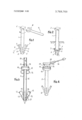
- FIG. 1 is a perspective view of a first embodiment of the present invention
- FIG. 2 is a perspective view of the anchoring device of FIG. 1 installed in the ground;
- FIG. 3 is a partial cross-sectional side elevation view of a second embodiment of the inventiondepicting a tool utilized in the installation of the device;
- FIG. 4 is a perspective view of the embodiment of FIG. 3, FIG. 4 showing the tool by which the device may be rotated after installation in the ground.
- a first embodiment of the invention comprises an elongated rod 1 terminating at one end in a head 2 of square cross-section.
- the opposite end 3 of rodl is, as shown in FIG. 2, the end which is adapted to be driven into the ground.
- the rod is provided with four vanes 5 which are welded onto the lateral wall of rod 1.
- Vanes S consist of flat metal bars arranged in such a manner that the angle a which they form with the rod portion to the head side of .their points of attachm'ent will be an acute angle.
- Each of vanes 5 is provided, on two opposite edges at a point intermediate its length, with notches 6 which define a zone of reduced resistance c around which the free ends 7 of the vanes can bend. These zones c of reduced resistance define lines which form an obtuse angle b with the portion of rod 1 to the head side of the vanes.
- the anchoringdevice of the embodiment of FIGS. 1 and 2 is driven into the ground to the desired depth, which will be commensurate with a point intermediate the length of rod 1, by striking the head 2 with a suitable weighted object.
- the rod is caused to rotate about its own axis by means of a tool such as wrench 8 fitted with a long handle 9.
- a tool such as wrench 8 fitted with a long handle 9.
- the free end portions 7 of the vanes are subjected to greater lateral force than the parts of the vanes which are supported on the rod since the end portions 7 are further away from the axis of rotation and thus have to move over a greater distance.
- the vanes 5 accordingly tend to bend and, due to the presence of the notches 6, the free ends 7 will be bent over comparatively easily.
- the bending over of the ends 7 of vanes 5 reduces the force required for rotation of the device and will result in the ends 7 spreading out in a direction which is substantially transverse to the axis of rod 1.
- the free ends of the vanes 7 will come to rest against the bending zones 0 of the adjacent vanes as shown in FIG. 2. In this position the device will offer considerable resistance to any force tending to pull it out of the ground and the device can be applied to a number of purposes such as, for example, the anchoring of guy wires.
- the boundary marker embodiment comprises a tubular member 11 provided'with vanes 12 adjacent its leading end. As in the embodiment of FIGS. 1 and 2, the vanes 12 of FIG. 3 are provided with notches 13 at an intermediate point along their length.
- the upper end of tubular member 11 is integral with a spherical cap 14 provided with a pair of oppositely disposed holes 15.
- the boundary marker device is designed to be driven into the ground with the aid ofa bar 16 having a pointed lower end 17.
- the upper end of bar 16 defines a head 18 which is comparatively heavy and coaxially prolonged by a tenon 19.
- One end of a handle member 20 is fitted on tenon 19 and these elements are thereafter assembled by a pin 21 which is passed through aligned holes in tenon 19 and hole. 20.
- the bar 16 is slightly longer than tubular member 11 and the boundary device may thus be driven into the ground by sliding the bar 16 within member 11 so that the point 17 of bar 16 bores a hole and the head 18, periodically impacting against the upper end of member 11, drives the device downwardly into the pilot hole formed by bar 16.
- Tool 22 comprises a bent sleeve defining a socket at one end which receives the end of bar 16.
- the bent sleeve is provided with a pair of radial points 23 designed to engage the holes 15 in spherical cap 14 of member 11.
- An anchoring device of the type adapted to be driven into the ground, saiddevice' comprising:
- each of said vanes including:
- a flat metal bar said bar being provided with oppositely disposed notches in its side edges intermediate the ends of said bar for the purpose of defining a weakened portion thereof whereby rotation of said elongated member after insertion in the ground will result in the bending of said vanes, said weakened portion defining a line which forms an obtuse angle with said axis of said elongated member, the oppositely disposed faces of said bar between said side edges lying entirely in parallel planes prior to rotation of said elongated member, the length of the portion of the bar between the weakened portion and the free end thereof being greater. than the spacing between adjacent vanes at the weakened portion thereof; and
- a head on the second end'of said tubular member said head being provided with a pair of holes in its upper surface, said holes being located apart.
Landscapes
- Engineering & Computer Science (AREA)
- Structural Engineering (AREA)
- Architecture (AREA)
- Civil Engineering (AREA)
- Life Sciences & Earth Sciences (AREA)
- General Life Sciences & Earth Sciences (AREA)
- Mining & Mineral Resources (AREA)
- Paleontology (AREA)
- General Engineering & Computer Science (AREA)
- Piles And Underground Anchors (AREA)
Abstract
An anchoring device comprising an elongated member, a plurality of inclined lateral vanes extending from said elongated member adjacent a first ground penetrating end thereof, said vanes each forming an acute angle with the axis of said elongated member and being provided with a weakened portion intermediate its length whereby rotation of said elongated member after insertion in the ground will result in the bending of said vanes and head means on the second end of said elongated member for enabling the rotation of said member.
Description
ilmted States Patent 1 1 3,769,768 Bertrand Nov. 6, 1973 [54] ANCHORING DEVICE 3,302,347 2/1967 Jackson 52/154 a 3,330,632 7 1967 De Moor 52 160 x [761 Inventor: Jean Jacques Bertrand 3,685,237 8/1972 Johnson 52/98 11, Rue de Breban 51, H 7 g a WWW Primary ExaminerPrice C. Faw, Jr. 2 2] Filed: May 24, 1972 AttorneyDavid S. Fishman et al.
[21] App]. No.: 256,439
[57] ABSTRACT [30] Foreign Application Priority Data An anchoring device comprising an elongated member, May 25 1971 France 71 l8762 a plurality ihchhed lateral "ahes extending fwm said elongated member adjacent a first ground penetrating 521 US. Cl 52/154 52/98 52/127 end that, said "ants each fmmihg acute angle 51 Int. Cl E626 5/80 with the axis 0f said ehhgated member and being [58] Field of Search 52/154 153 165 vided with a weakened P intermediate its length 52/155 156 57 158 159 whereby rotation ofsaid elongated member after insertion in the ground will result in the bending ofv said 7 g vanes and head 'means on the second end of said elon- [56] References Cited gated member for enabling the rotation of said mem- UNITED STATES PATENTS Rl0,366 8/1883 Oliver 52 154 1 Claim, 4 Drawing Figures 841,812 1/1907 Pement 52/157 mlLINCHORING DEVICE BACKGROUND OF THE INVENTION 1. Field of the Invention The present invention relates to anchoring devices adapted to be driven into the ground for the purpose of providing boundary markings, points of attachment for guy wires and other similar purposes. Accordingly, the general objects of the present invention are to provide novel and improved apparatus of such character.
2. Description of the Prior Art Numerous ground engaging anchor devices are known in the art. One of the more popular previously available devices includes a rod bent helically; the device being driven into the ground by rotation about the longitudinal axis of the helix. An anchor of the helical type is quite difficult to accidentally withdraw from the ground but suffers from the drawback of requiring a comparatively long time to insert in the ground.
Devices easier to install than the previously described helical anchors have been proposed. A number of such devices comprise a rod having, adjacent the end which is driven into the ground, a plurality of outwardly extending studs or vanes. Anchors characterized by vanes may be installed more easily than the devices which have to be rotated but suffer from the disadvantage that the laterally extending parts disturb the ground as the device is driven into the ground and accordingly the devices may be withdrawn with comparative ease.
Anchor devices are also known wherein the main rod portion is provided with pivotal lateral projections in the vicinity of the leading end. These projections are designed to spread outwardly when an attempt is made to withdraw the anchor thereby enhancing the anchor-- ing effect. Devices with the movable projections possess the inherent disadvantages that they are comparatively expensive, when compared to other devices for performing the same function, and after the devices have been installed for a period of time soil tends to clog the joints thereby possibly preventing the spreading'of the projections when the withdrawing force is applied. Additionally, such devices must be extracted a limited distance in order to obtainmaximum retention effect from the movable projections thereby permitting, at the very least, a degree of vertical movement which may be undesirable.
SUMMARY OF THE INVENTION The present invention overcomes the above briefly discussed and other deficiencies and disadvantages of the prior art by providing a novel and improved an-' choring device which is easy to use, economic to produce and which will resist considerable tractive stress without being pulled from the ground. In accomplishing the above objectives the present invention comprises an elongated member having a first end which will be driven into the ground. The elongated member, adjacent its ground penetrating end, is provided with a plurality of lateral vanes which are oriented so as to define acute angles with the axis of the member at the side thereof which terminates in the second end. The'inclined vanes are each provided with a weakened portion which facilitates the bending of the vanes at a point intermediate their length. The second or head end of the elongated member, which is engaged by a suitable tool or object to drive the device into the ground, is further provided with means which enable the member to be engaged by a tool in order to rotate the elongated member about its axis after it has been driven into the ground to the desired depth.
In accordance with a preferred embodiment, the devices of the present invention are driven into the ground by striking the second or upper end with a suitable weighted object. Thereafter the elongated member portion of the devices are engaged by a suitable tool and rotated through an angle of approximately 90. During rotation the inclined vanes will be subjected to considerable strain and will bend about the weakened point intermediate their length. The bending action will result in the upper portions of the vanes spreading out transversely to the axis of the elongated member thereby providing means which will resist considerable tractive stresses attempting to withdraw the device from the ground.
In a preferred embodiment of the invention the weakened part of each of the vanes defines a line which forms an obtuse angle with the axis of that portion of the elongated member located to the second or head end side of the vanes. Accordingly, by providing the vanes with sufficient length, upon rotation the free ends of the vanes will come to rest against the adjacent vanes after the elongated member has been rotated. Accordingly, when a vertical tractive force is applied the vanes will be supported on one another and will be unable to bend any further about the weakened portions. In accordance with the preferred embodiment each vane will be comprised of a flat metal bar with the weakened portion which enables the vanes to be bent over after installation consisting of at least one notch provided along an edgeof each bar.
The elongated member portion of the devices of the present invention may be comprised of the tubular element open at both ends. If such a tubular element is employed the device may be inserted into the ground with the aid of a pointed bar which is inserted through the tubular element and extends beyond the first end thereof. The device is installed by striking the head portion of the pointed bar whereby the pointed end produces a preliminary'or pilot hole which facilitates the penetration of the ground. The use of a tubular elongated member and pointed rod is particularly advantageous when the anchoring devices are to be installed in rocky ground.
- ing a pair of holes located apart. This enables the rotational movement to be imparted to the anchoring device by means of a simple lever which is provided, adjacent one of its ends, with two parallel radial points designed to interact with the holes in the head of the elongated member.
The present invention also encompasses a tool for use in the installation of embodiments of the anchoring devices which are characterized by an elongated member comprised of a tubular element. The installation tool comprises the aforementioned pointed bar which is provided with a detachable coaxial handle at its other or head end. This arrangement permits insertion of the anchoring device into the ground by causing the bar to slide alternately in one direction and then in the other with the point on the bar producing a preliminary hole in the ground on each downward movement while the head, when contacting the upper end of the anchoring device elongated member, pushes the anchoring device vertically downwards. The tool may also include a bent socket adapted as a first end to be engaged by the elongated member and, at its other end, being provided with the two parallel radial points designed to interconnect with the holes in the head of the anchoring device to achieve rotation.
BRIEF DESCRIPTION OF THE DRAWING The present invention may be better understood and its numerous objects and advantages will become apparent to those skilled in the art by reference to the accompanying drawing wherein like reference numerals refer to like elements in the several figures and in which:
FIG. 1 is a perspective view of a first embodiment of the present invention;
FIG. 2 is a perspective view of the anchoring device of FIG. 1 installed in the ground;
FIG. 3 is a partial cross-sectional side elevation view of a second embodiment of the inventiondepicting a tool utilized in the installation of the device; and
FIG. 4 is a perspective view of the embodiment of FIG. 3, FIG. 4 showing the tool by which the device may be rotated after installation in the ground.
DESCRIPTION OF THE PREFERRED EMBODIMENTS Referring first simultaneously to FIGS. 1 and 2, a first embodiment of the invention comprises an elongated rod 1 terminating at one end in a head 2 of square cross-section. The opposite end 3 of rodl is, as shown in FIG. 2, the end which is adapted to be driven into the ground. In the vicinity of end 3 the rod is provided with four vanes 5 which are welded onto the lateral wall of rod 1. Vanes S consist of flat metal bars arranged in such a manner that the angle a which they form with the rod portion to the head side of .their points of attachm'ent will be an acute angle.
Each of vanes 5 is provided, on two opposite edges at a point intermediate its length, with notches 6 which define a zone of reduced resistance c around which the free ends 7 of the vanes can bend. These zones c of reduced resistance define lines which form an obtuse angle b with the portion of rod 1 to the head side of the vanes.
The anchoringdevice of the embodiment of FIGS. 1 and 2 is driven into the ground to the desired depth, which will be commensurate with a point intermediate the length of rod 1, by striking the head 2 with a suitable weighted object. After the device has been inserted in the ground the rod is caused to rotate about its own axis by means of a tool such as wrench 8 fitted with a long handle 9. During rotation, which should be through an angle of approximately 90, the free end portions 7 of the vanes are subjected to greater lateral force than the parts of the vanes which are supported on the rod since the end portions 7 are further away from the axis of rotation and thus have to move over a greater distance. The vanes 5 accordingly tend to bend and, due to the presence of the notches 6, the free ends 7 will be bent over comparatively easily. The bending over of the ends 7 of vanes 5 reduces the force required for rotation of the device and will result in the ends 7 spreading out in a direction which is substantially transverse to the axis of rod 1. By proper positioning of the notches 6 and selection of the length of the vanes 5 the free ends of the vanes 7 will come to rest against the bending zones 0 of the adjacent vanes as shown in FIG. 2. In this position the device will offer considerable resistance to any force tending to pull it out of the ground and the device can be applied to a number of purposes such as, for example, the anchoring of guy wires.
With reference now to FIGS. 3 and 4, an embodiment of the invention particularly well suited for use by surveyors for marking boundaries is shownsThe boundary marker embodiment comprises a tubular member 11 provided'with vanes 12 adjacent its leading end. As in the embodiment of FIGS. 1 and 2, the vanes 12 of FIG. 3 are provided with notches 13 at an intermediate point along their length. The upper end of tubular member 11 is integral with a spherical cap 14 provided with a pair of oppositely disposed holes 15. The boundary marker device is designed to be driven into the ground with the aid ofa bar 16 having a pointed lower end 17. The upper end of bar 16 defines a head 18 which is comparatively heavy and coaxially prolonged by a tenon 19. One end ofa handle member 20 is fitted on tenon 19 and these elements are thereafter assembled by a pin 21 which is passed through aligned holes in tenon 19 and hole. 20. The bar 16 is slightly longer than tubular member 11 and the boundary device may thus be driven into the ground by sliding the bar 16 within member 11 so that the point 17 of bar 16 bores a hole and the head 18, periodically impacting against the upper end of member 11, drives the device downwardly into the pilot hole formed by bar 16.
In order to rotate the boundary device after it has been driven to the desired depth, the tool 22 of FIG. 4 may be employed. Tool 22 comprises a bent sleeve defining a socket at one end which receives the end of bar 16. The bent sleeve is provided with a pair of radial points 23 designed to engage the holes 15 in spherical cap 14 of member 11.
While preferred embodiments have been shown and described various modifications and substitutions may be made thereto without departing from the spirit and scope of the invention. Accordingly, it is to be understood that the present invention has been described by way'of illustration and not limitation.
What is claimed is:
1. An anchoring device of the type adapted to be driven into the ground, saiddevice' comprising:
an elongated tubular member open at both ends;
a plurality of inclined lateral vanes extending from said elongated member adjacent a first ground penetrating end thereof, said vanes each forming an acute angle with the axis of said elongated member, each of said vanes including:
a flat metal bar, said bar being provided with oppositely disposed notches in its side edges intermediate the ends of said bar for the purpose of defining a weakened portion thereof whereby rotation of said elongated member after insertion in the ground will result in the bending of said vanes, said weakened portion defining a line which forms an obtuse angle with said axis of said elongated member, the oppositely disposed faces of said bar between said side edges lying entirely in parallel planes prior to rotation of said elongated member, the length of the portion of the bar between the weakened portion and the free end thereof being greater. than the spacing between adjacent vanes at the weakened portion thereof; and
a head on the second end'of said tubular member, said head being provided with a pair of holes in its upper surface, said holes being located apart.
Claims (1)
1. An anchoring device of the type adapted to be driven into the ground, said device comprising: an elongated tubular member open at both ends; a plurality of inclined lateral vanes extending from said elongated member adjacent a first ground penetrating end thereof, said vanes each forming an acute angle with the axis of said elongated member, each of said vanes including: a flat metal bar, said bar being provided with oppositely disposed notches in its side edges intermediate the ends of said bar for the purpose of defining a weakened portion thereof whereby rotation of said elongated member after insertion in the ground will result in the bending of said vanes, said weakened portion defining a line which forms an obtuse angle with said axis of said elongated member, the oppositely disposed faces of said bar between said side edges lying entirely in parallel planes prior to rotation of said elongated member, the length of the portion of the bar between the weakened portion and the free end thereof being greater than the spacing between adjacent vanes at the weakened portion thereof; and a head on the second end of said tubular member, said head being provided with a pair of holes in its upper surface, said holes being located 180* apart.
Applications Claiming Priority (1)
| Application Number | Priority Date | Filing Date | Title |
|---|---|---|---|
| FR7118762A FR2095035A5 (en) | 1971-05-25 | 1971-05-25 |
Publications (1)
| Publication Number | Publication Date |
|---|---|
| US3769768A true US3769768A (en) | 1973-11-06 |
Family
ID=9077551
Family Applications (1)
| Application Number | Title | Priority Date | Filing Date |
|---|---|---|---|
| US00256439A Expired - Lifetime US3769768A (en) | 1971-05-25 | 1972-05-24 | Anchoring device |
Country Status (7)
| Country | Link |
|---|---|
| US (1) | US3769768A (en) |
| BR (1) | BR7203244D0 (en) |
| DE (1) | DE2138964B2 (en) |
| FR (1) | FR2095035A5 (en) |
| GB (1) | GB1347591A (en) |
| IT (1) | IT958834B (en) |
| OA (1) | OA04088A (en) |
Cited By (9)
| Publication number | Priority date | Publication date | Assignee | Title |
|---|---|---|---|---|
| US5095667A (en) * | 1990-03-07 | 1992-03-17 | Chester Ryan | Telescopic manhole and storm drain installation |
| US5224310A (en) * | 1991-11-18 | 1993-07-06 | A. B. Chance Company | Hand-installed landscape foundation |
| US5295336A (en) * | 1987-05-12 | 1994-03-22 | Egaas Roy B | Releasable post anchoring device |
| US6018920A (en) * | 1997-10-01 | 2000-02-01 | Fancher; Hershel E. | Modular panel assembly system |
| US6050034A (en) * | 1995-07-28 | 2000-04-18 | Klaus Krinner | Anchoring device for a pole- or post-like object |
| US6253517B1 (en) * | 1997-10-01 | 2001-07-03 | Hershel E. Fancher | Modular panel assembly system |
| US20040115009A1 (en) * | 2002-12-13 | 2004-06-17 | Bradley John J. | Ground retention stake for outdoor pedestal |
| DE102005023663A1 (en) * | 2005-05-23 | 2006-11-30 | Müller, Thomas | Base sleeve for e.g. inserting in soil, has anvil surface with bilateral or multilateral edge, and retaining plate adjustable and/or movable in all directions so that pipe, rod and pillar are arranged after inserting in shank and fastened |
| US7437857B1 (en) * | 2004-02-11 | 2008-10-21 | Spectrum Products, Llc | Compression anchor |
Families Citing this family (4)
| Publication number | Priority date | Publication date | Assignee | Title |
|---|---|---|---|---|
| GB2087460B (en) * | 1980-10-15 | 1984-05-31 | Pandrol Ltd | Rail clip anchorages |
| GB2130267B (en) * | 1982-11-08 | 1985-10-16 | Brian John | Ground fixing support |
| GB2140842A (en) * | 1983-03-07 | 1984-12-05 | Terence Roland Dunn | Finned post socket for driving into the ground |
| FR2660026B1 (en) * | 1990-03-26 | 1992-05-29 | Bertrand Dominique | ANCHORING DEVICE. |
Citations (5)
| Publication number | Priority date | Publication date | Assignee | Title |
|---|---|---|---|---|
| US10366A (en) * | 1854-01-03 | Method of hanging and operating saw-gates | ||
| US841812A (en) * | 1906-09-05 | 1907-01-22 | Philemon Pement | Tent-stake. |
| US3302347A (en) * | 1964-11-27 | 1967-02-07 | Zelm Associates Inc Van | Drive anchors with retaining flukes |
| US3330632A (en) * | 1965-05-10 | 1967-07-11 | Jasper Blackburn Corp | Earth anchor wing |
| US3685237A (en) * | 1970-02-24 | 1972-08-22 | John David Johnson | Property boundary marker |
Family Cites Families (1)
| Publication number | Priority date | Publication date | Assignee | Title |
|---|---|---|---|---|
| US2999572A (en) * | 1958-02-12 | 1961-09-12 | John D Hinckley | Earth anchor |
-
1971
- 1971-05-25 FR FR7118762A patent/FR2095035A5/fr not_active Expired
- 1971-08-04 DE DE2138964A patent/DE2138964B2/en not_active Withdrawn
-
1972
- 1972-05-09 GB GB2157672A patent/GB1347591A/en not_active Expired
- 1972-05-10 IT IT68463/72A patent/IT958834B/en active
- 1972-05-17 OA OA54572A patent/OA04088A/en unknown
- 1972-05-23 BR BR3244/72A patent/BR7203244D0/en unknown
- 1972-05-24 US US00256439A patent/US3769768A/en not_active Expired - Lifetime
Patent Citations (5)
| Publication number | Priority date | Publication date | Assignee | Title |
|---|---|---|---|---|
| US10366A (en) * | 1854-01-03 | Method of hanging and operating saw-gates | ||
| US841812A (en) * | 1906-09-05 | 1907-01-22 | Philemon Pement | Tent-stake. |
| US3302347A (en) * | 1964-11-27 | 1967-02-07 | Zelm Associates Inc Van | Drive anchors with retaining flukes |
| US3330632A (en) * | 1965-05-10 | 1967-07-11 | Jasper Blackburn Corp | Earth anchor wing |
| US3685237A (en) * | 1970-02-24 | 1972-08-22 | John David Johnson | Property boundary marker |
Cited By (11)
| Publication number | Priority date | Publication date | Assignee | Title |
|---|---|---|---|---|
| US5295336A (en) * | 1987-05-12 | 1994-03-22 | Egaas Roy B | Releasable post anchoring device |
| US5095667A (en) * | 1990-03-07 | 1992-03-17 | Chester Ryan | Telescopic manhole and storm drain installation |
| US5224310A (en) * | 1991-11-18 | 1993-07-06 | A. B. Chance Company | Hand-installed landscape foundation |
| US6050034A (en) * | 1995-07-28 | 2000-04-18 | Klaus Krinner | Anchoring device for a pole- or post-like object |
| US6018920A (en) * | 1997-10-01 | 2000-02-01 | Fancher; Hershel E. | Modular panel assembly system |
| US6253517B1 (en) * | 1997-10-01 | 2001-07-03 | Hershel E. Fancher | Modular panel assembly system |
| US20040115009A1 (en) * | 2002-12-13 | 2004-06-17 | Bradley John J. | Ground retention stake for outdoor pedestal |
| US6922954B2 (en) * | 2002-12-13 | 2005-08-02 | Corning Cable Systems Llc | Ground retention stake for outdoor pedestal |
| US7437857B1 (en) * | 2004-02-11 | 2008-10-21 | Spectrum Products, Llc | Compression anchor |
| DE102005023663A1 (en) * | 2005-05-23 | 2006-11-30 | Müller, Thomas | Base sleeve for e.g. inserting in soil, has anvil surface with bilateral or multilateral edge, and retaining plate adjustable and/or movable in all directions so that pipe, rod and pillar are arranged after inserting in shank and fastened |
| DE102005023663B4 (en) * | 2005-05-23 | 2009-05-14 | Müller, Thomas | ground socket |
Also Published As
| Publication number | Publication date |
|---|---|
| DE2138964A1 (en) | 1972-12-07 |
| FR2095035A5 (en) | 1972-02-04 |
| GB1347591A (en) | 1974-02-27 |
| BR7203244D0 (en) | 1974-08-29 |
| OA04088A (en) | 1979-10-30 |
| IT958834B (en) | 1973-10-30 |
| DE2138964B2 (en) | 1973-11-08 |
Similar Documents
| Publication | Publication Date | Title |
|---|---|---|
| US3769768A (en) | Anchoring device | |
| US6871455B1 (en) | Drive/auger anchor and stabilizer | |
| US3012644A (en) | Anchor pile | |
| US3888057A (en) | Ground anchor with pivoting fluke | |
| EA011700B1 (en) | An anchoring device | |
| US2396276A (en) | Expansible prong device | |
| US5010698A (en) | Anchoring post assembly | |
| US1940938A (en) | Earth anchor | |
| US3080024A (en) | Ground anchor | |
| US3861097A (en) | Earth anchor | |
| US3378968A (en) | Cement form stake | |
| US3431924A (en) | Tent stake | |
| KR20100022767A (en) | A rock bed extension type ground anchor | |
| US2063052A (en) | Self-securing and propelling anchor | |
| KR101927736B1 (en) | A soil ancher having excellent ground fixing force and constructing method for planting mat or retaining wall using thereof | |
| US728609A (en) | Guy-anchor. | |
| US1273890A (en) | Drive-anchor. | |
| CH449984A (en) | Boundary mark for surveying purposes and for marking property boundaries | |
| US1422301A (en) | Post for wire fencing | |
| US20090309007A1 (en) | Concrete form anchor device, system and method for forming trenches | |
| US1408007A (en) | Metallic fencepost | |
| CH674872A5 (en) | ||
| KR102039997B1 (en) | Supporting piller for pepper | |
| US1049549A (en) | Metal fence-post. | |
| US1659210A (en) | Post anchor |
Legal Events
| Date | Code | Title | Description |
|---|---|---|---|
| AS | Assignment |
Owner name: SOCIETE SPAR-AGRO, 08450 REMILLY-AILLICOURT, FRANC Free format text: ASSIGNMENT OF ASSIGNORS INTEREST.;ASSIGNOR:BERTRAND, JEAN-JACQUES;REEL/FRAME:004527/0397 Effective date: 19841001 |