US3767971A - Static bleed resistor - Google Patents
Static bleed resistor Download PDFInfo
- Publication number
- US3767971A US3767971A US00140461A US3767971DA US3767971A US 3767971 A US3767971 A US 3767971A US 00140461 A US00140461 A US 00140461A US 3767971D A US3767971D A US 3767971DA US 3767971 A US3767971 A US 3767971A
- Authority
- US
- United States
- Prior art keywords
- bleed resistor
- static
- static bleed
- tow
- resistor
- Prior art date
- Legal status (The legal status is an assumption and is not a legal conclusion. Google has not performed a legal analysis and makes no representation as to the accuracy of the status listed.)
- Expired - Lifetime
Links
- 230000003068 static effect Effects 0.000 title claims abstract description 55
- 239000000835 fiber Substances 0.000 claims abstract description 18
- 239000004033 plastic Substances 0.000 claims abstract description 9
- 239000011159 matrix material Substances 0.000 claims description 15
- 230000000740 bleeding effect Effects 0.000 abstract description 3
- 239000002131 composite material Substances 0.000 abstract description 3
- 239000012260 resinous material Substances 0.000 abstract description 2
- 229910052751 metal Inorganic materials 0.000 description 8
- 239000002184 metal Substances 0.000 description 8
- 230000008878 coupling Effects 0.000 description 7
- 238000010168 coupling process Methods 0.000 description 7
- 238000005859 coupling reaction Methods 0.000 description 7
- 239000000853 adhesive Substances 0.000 description 5
- 230000001070 adhesive effect Effects 0.000 description 5
- 239000000463 material Substances 0.000 description 5
- OKTJSMMVPCPJKN-UHFFFAOYSA-N Carbon Chemical compound [C] OKTJSMMVPCPJKN-UHFFFAOYSA-N 0.000 description 4
- 229910052799 carbon Inorganic materials 0.000 description 4
- 230000005611 electricity Effects 0.000 description 4
- 239000000919 ceramic Substances 0.000 description 2
- 239000012141 concentrate Substances 0.000 description 2
- 239000004020 conductor Substances 0.000 description 2
- 230000003628 erosive effect Effects 0.000 description 2
- 238000000034 method Methods 0.000 description 2
- 230000035515 penetration Effects 0.000 description 2
- 239000000088 plastic resin Substances 0.000 description 2
- 229920000049 Carbon (fiber) Polymers 0.000 description 1
- 229920005123 Celcon® Polymers 0.000 description 1
- 229920004943 Delrin® Polymers 0.000 description 1
- 229920004459 Kel-F® PCTFE Polymers 0.000 description 1
- 229920000297 Rayon Polymers 0.000 description 1
- 239000004809 Teflon Substances 0.000 description 1
- 229920006362 Teflon® Polymers 0.000 description 1
- 239000004917 carbon fiber Substances 0.000 description 1
- 229920002678 cellulose Polymers 0.000 description 1
- 239000001913 cellulose Substances 0.000 description 1
- UUAGAQFQZIEFAH-UHFFFAOYSA-N chlorotrifluoroethylene Chemical compound FC(F)=C(F)Cl UUAGAQFQZIEFAH-UHFFFAOYSA-N 0.000 description 1
- 230000000295 complement effect Effects 0.000 description 1
- 229920001577 copolymer Polymers 0.000 description 1
- IDLFZVILOHSSID-OVLDLUHVSA-N corticotropin Chemical compound C([C@@H](C(=O)N[C@@H](CO)C(=O)N[C@@H](CCSC)C(=O)N[C@@H](CCC(O)=O)C(=O)N[C@@H](CC=1NC=NC=1)C(=O)N[C@@H](CC=1C=CC=CC=1)C(=O)N[C@@H](CCCNC(N)=N)C(=O)N[C@@H](CC=1C2=CC=CC=C2NC=1)C(=O)NCC(=O)N[C@@H](CCCCN)C(=O)N1[C@@H](CCC1)C(=O)N[C@@H](C(C)C)C(=O)NCC(=O)N[C@@H](CCCCN)C(=O)N[C@@H](CCCCN)C(=O)N[C@@H](CCCNC(N)=N)C(=O)N[C@@H](CCCNC(N)=N)C(=O)N1[C@@H](CCC1)C(=O)N[C@@H](C(C)C)C(=O)N[C@@H](CCCCN)C(=O)N[C@@H](C(C)C)C(=O)N[C@@H](CC=1C=CC(O)=CC=1)C(=O)N1[C@@H](CCC1)C(=O)N[C@@H](CC(N)=O)C(=O)NCC(=O)N[C@@H](C)C(=O)N[C@@H](CCC(O)=O)C(=O)N[C@@H](CC(O)=O)C(=O)N[C@@H](CCC(O)=O)C(=O)N[C@@H](CO)C(=O)N[C@@H](C)C(=O)N[C@@H](CCC(O)=O)C(=O)N[C@@H](C)C(=O)N[C@@H](CC=1C=CC=CC=1)C(=O)N1[C@@H](CCC1)C(=O)N[C@@H](CC(C)C)C(=O)N[C@@H](CCC(O)=O)C(=O)N[C@@H](CC=1C=CC=CC=1)C(O)=O)NC(=O)[C@@H](N)CO)C1=CC=C(O)C=C1 IDLFZVILOHSSID-OVLDLUHVSA-N 0.000 description 1
- 230000002542 deteriorative effect Effects 0.000 description 1
- 238000010891 electric arc Methods 0.000 description 1
- 230000007613 environmental effect Effects 0.000 description 1
- 229940014425 exodus Drugs 0.000 description 1
- 239000011521 glass Substances 0.000 description 1
- 238000012986 modification Methods 0.000 description 1
- 230000004048 modification Effects 0.000 description 1
- 230000008520 organization Effects 0.000 description 1
- 230000000149 penetrating effect Effects 0.000 description 1
- 229920006324 polyoxymethylene Polymers 0.000 description 1
- 230000002265 prevention Effects 0.000 description 1
- 239000002964 rayon Substances 0.000 description 1
- 229910052709 silver Inorganic materials 0.000 description 1
- 239000004332 silver Substances 0.000 description 1
Images
Classifications
-
- H—ELECTRICITY
- H05—ELECTRIC TECHNIQUES NOT OTHERWISE PROVIDED FOR
- H05F—STATIC ELECTRICITY; NATURALLY-OCCURRING ELECTRICITY
- H05F3/00—Carrying-off electrostatic charges
Definitions
- ABSTRACT This invention covers a drain for electrostatic charge commonly called a static bleed resistor in which a resistance element forms the core of a composite structure which includes a non-tracking plastic resinous material.
- the core may be made from a fibrous tow, and in this event, one end of the fibers making up the tow may be exposed to the atmosphere to constitute the active bleeding elements.
- INV E NTOR STATIC BLEED RESISTOR The prevention of the buildup of an electrostatic charge on an insulated conducting body is typically accomplished with a sharp pointed conducting rod attached to the body. The charge concentrates, typically, at the point. Because of the high charge density at the sharp point, ionization of the surrounding air occurs and the charge bleeds away. Generally, in most applications, it is necessary to limit the current that flows through the bleeder resistor to prevent sparking. This is accomplished by making the resistance means of the rod very high, several million ohms.
- the static bleed resistor must also be able to withstand lightening strikes to the body that it is protecting because it is in itself the logical point of exodus for the lightening bolt from the body into the surrounding atmosphere.
- a static bleed resistor which (1) is self-healing; (2) is resistant to atmospheric erosion and other deteriorating effects of the atmosphere; (3) contains an internal resistance network provided with an essentially non-conducting surface so that it can be used in improved lightening handling techniques; (4) is formed from a non-tracking matrix to maintain an essentially non-conducting surface when raised to temperatures where tracking materials char; and (5) contains a fibrous tow resistance element which prevents lightening penetration.
- a static bleed resistor comprises an electrical resistance element substantially enclosed within a non-tracking plastic resin matrix.
- the resistor is provided with an electrical coupling means for coupling the resistance element to the body which the static bleed resistor is intended to protect.
- a discharge means is also provided.
- the resistance element is formed from a fibrous tow formed from electrically conducting material.
- the terminal edges of one end of the tow may be exposed to the atmosphere so that each exposed fiber edge acts as the means for coupling the static charge to the atmosphere, a discharge means.
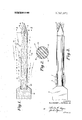
- FIG. 1 of the drawing is a cross-sectional representation of a static bleed resistor embodying the principles of the present invention.
- FIG. 2 is an end view taken along line 22 showing in detail the static bleeding means.
- FIG. 3 is a pictorial representation of the static bleed resistor in an operational assembly.
- FIG. 1 of the drawing there is shown a static bleed resistor comprising an electrical resistance means 13 embedded within a plastic matrix ll.
- the static bleed resistor 10 is coupled to a metal body 12 through an electrical coupling means 20.
- the body 12 represents figuratively the member from which static electricity is to be bled.
- the electrical coupling means 20 is preferably an electrically conductive adhesive such as the adhesive sold under the designation C34 made by the National Carbon Company. Chromerics and Emerson Cummings are two other sources of conductive adhesive.
- a conducting adhesive is essentially an adhesive loaded with carbon, silver or other conductor.
- the electrical coupling means may comprise a threading recess portion in the body 12 with a complementary threaded end of the static bleed resistor 10.
- the static bleed resistor 10 is a composite structure with an electrical resistance means 13 embedded within a non-conducting plastic matrix 11.
- the electrical resistance means 13 is represented by a fibrous tow made up from either continuous carbon filaments or staple carbon fibers.
- the tow is made up of an extremely large number about 105 of extremely high resistance fibers to prevent lightening from penetrating into the tow via an occasional fiber that may be near or at the surface of the bleeder resistor.
- the tow is constructed from carbon filaments formed, as is widely done from a cellulose material such as rayon or from PAN or acronym for polyacylatonitrile.
- a cellulose material such as rayon or from PAN or acronym for polyacylatonitrile.
- Other filaments such as glass coated filaments are also applicable.
- the specific resistance material is not critical, though the resistance per unit length of the filament is.
- each filament should exceed 10" ohms. Accordingly, in the order of 100,000, about 14 micron in diameter filaments are required to make up a static bleed resistor. Typically, static bleed resistors are 8-10 inches long and have a total longitudinal resistance of 5 X 10 to 100 X 10 ohms.
- the electrical resistance means 13 is made up of a large number of parallel essentially insulated longitudinal electrical conducting paths for the electrostatic charge to traverse. Theoretically, there are as many parallel essentially insulated longitudinal electrical conductingpaths as-there are filaments, for example. Additionally, there are a number of finite interconnections between the parallel fibers so that if one or a number of paths formed by the length of a fiber is broken, it may be circumvented by a parallel path through a pair of interconnections.
- non-conducting and preferably a non-tracking, plastic matrix.
- nontracking as applied to the plastic resin matrix 11 is hereby defined to mean a material which does not form a carbonacious or other electrically conducting path when thermally dissipated as might occur by a spark or an arc discharge.
- Typical non-tracking matrix materials are homoor copolymers of polyformaldehyde such as Delrin and Celcon.
- An epoxy-urethane system sold by the Assignee as the 21 system as well as the fluorocarbons known as Teflon and Kel-F are also suitable non-tracking materials.
- the preferable means involves the use of fibers, a small number of these fibers will appear at the surface of the plastic as shown by the symbol 15 in FIG. 1. These do not materially affect the operation of the static bleed resistor because these surface penetrations are essentially isolated because of the high fiber and high overall resistance. They also tend to disappear due to environmental erosion or by distruction during a lightening strike. It may be accurately stated that the surface of the static bleed resistor consistsof essentially the non-tracking matrix material, except for the discharge end 17 where the fiber ends are deliberately exposed.
- the static bleed resistor contains a static bleed means which in this case comprises the discharge end 17.
- the end 17 is in the form of a sharp pointed cone to concentrate the static electricity and to simplify the ionization of the surrounding air so that the static electricity may be bled from the resister 10 to the atmosphere. 5
- ends 16 of the fiber resistance means 13 exposed to the atmosphere on the surface of the conical discharge end17.
- Each of these ends exposed per se represents a high electrical stress region so that each one I acts as an effective coupling means between the static bleed resistor 10 and the atmosphere.
- Each of these ends 16 acts as a substitute for the tip of a metal cap, the conventional discharge end.
- the static bleed resistor 10 is shown within an assembly.
- the assembly includes in addition to the static bleed resistor, a metal sleeve 23, securely fastened to the cylindrical surface of the static bleed resistor 10.
- the metal sleeve does not affect the performance of the static bleed resistor since it is isolated from the electrical resistance means 13 by the plastic matrix 11.
- the metal sleeve 23 operates to protect the static bleed resistor in the event of a lightening strike to the body 12.
- the flow of electricity tends to gravitate to the static bleed resistor 10 on the body in an ionized sheath along the surface of the body.
- the lightening bolt would, if it could, enter the resistor and traverse the resistance element. If this occurs, the static bleed resistor would be destroyed. This, in fact, occurs in prior art devices. It does not happen on the static bleedresistor described herein.
- the lightening traveling along the surface of the body encounters either the matrix or an isolated fiber.
- the air surrounding the static bleed resistor offers less resistance than the fiber having 10 inches ohm/in. Characteristically, therefore, the air around the static bleed resistor is converted .into an ionized sheath. The lightening current is dissipated into the atmosphere through this sheath.
- the lightening strike ionizes the air between the body 12 and around the metal sleeve 23. Since the metalsleeve 23 covers the major portion of the static bleed resistor surface, most of the lightening current is dissipated around the metal sleeve. The sleeve is able to withstand damage because of its excellent conductive qualties. The exposed surface areas of the static bleed resistor 10 are stressed less, and to the extent that the surfaces are burned, there is no conducting residue from the non-tracking matrix. The metal sleeve merely increases the reliability of the static bleed resistor against lightening strikes; its presence is not a necessity.
- a static bleed resistor comprising a longitudinal resistance element having a large number of parallel and essentially insulated longitudinal electrical conducting paths embedded within a non-tracking plastic matrix, each of said conducting paths having a resistance per length of about 10 ohms per inch.
Landscapes
- Elimination Of Static Electricity (AREA)
Applications Claiming Priority (1)
| Application Number | Priority Date | Filing Date | Title |
|---|---|---|---|
| US14046171A | 1971-05-05 | 1971-05-05 |
Publications (1)
| Publication Number | Publication Date |
|---|---|
| US3767971A true US3767971A (en) | 1973-10-23 |
Family
ID=22491328
Family Applications (1)
| Application Number | Title | Priority Date | Filing Date |
|---|---|---|---|
| US00140461A Expired - Lifetime US3767971A (en) | 1971-05-05 | 1971-05-05 | Static bleed resistor |
Country Status (5)
| Country | Link |
|---|---|
| US (1) | US3767971A (enExample) |
| CA (1) | CA958787A (enExample) |
| DE (1) | DE2221622A1 (enExample) |
| FR (1) | FR2135619B1 (enExample) |
| GB (1) | GB1393012A (enExample) |
Cited By (10)
| Publication number | Priority date | Publication date | Assignee | Title |
|---|---|---|---|---|
| US3898526A (en) * | 1971-06-01 | 1975-08-05 | Charles D Hendricks | Static discharge apparatus and several methods for manufacturing the static discharge apparatus |
| US4698723A (en) * | 1986-04-24 | 1987-10-06 | The United States Of America As Represented By The Administrator Of The National Aeronautics And Space Administration | Lightning discharge protection rod |
| US4733268A (en) * | 1986-05-09 | 1988-03-22 | International Business Machines Corporation | Voltage control bar for electrophotography |
| US5570265A (en) * | 1989-01-31 | 1996-10-29 | Hr Smith (Technical Developments) Limited | Static dischargers for aircraft |
| US5871060A (en) * | 1997-02-20 | 1999-02-16 | Jensen; Kenneth M. | Attachment geometry for non-planar drill inserts |
| US20050002165A1 (en) * | 2002-11-26 | 2005-01-06 | Samsung Electronics Co., Ltd | Laser diode for optical pickup and method of protection |
| WO2009120785A3 (en) * | 2008-03-25 | 2009-12-30 | Ebr Systems, Inc. | Implantable wireless acoustic stimulators with high energy conversion efficiencies |
| US20100234924A1 (en) * | 2008-03-25 | 2010-09-16 | Ebr Systems, Inc. | Operation and estimation of output voltage of wireless stimulators |
| US9180285B2 (en) | 2008-03-25 | 2015-11-10 | Ebr Systems, Inc. | Implantable wireless accoustic stimulators with high energy conversion efficiencies |
| US11654287B2 (en) | 2019-08-30 | 2023-05-23 | Ebr Systems, Inc. | Pulse delivery device including slew rate detector, and associated systems and methods |
Families Citing this family (2)
| Publication number | Priority date | Publication date | Assignee | Title |
|---|---|---|---|---|
| DE3305616A1 (de) * | 1983-02-18 | 1984-08-23 | Vorwerk & Co Interholding Gmbh, 5600 Wuppertal | Vorrichtung zur vermeidung elektrostatischer aufladungen |
| DE3931230A1 (de) * | 1989-09-20 | 1991-03-28 | Neuero Stahlbau Gmbh & Co | Magnetbahn |
Citations (4)
| Publication number | Priority date | Publication date | Assignee | Title |
|---|---|---|---|---|
| US2631189A (en) * | 1950-01-27 | 1953-03-10 | Dayton Aircraft Prod Inc | Static wick discharger |
| US3034020A (en) * | 1960-06-27 | 1962-05-08 | Dayton Aircraft Prod Inc | Static discharger |
| US3473087A (en) * | 1962-05-22 | 1969-10-14 | Raybestos Manhattan Inc | Electrically conductive polytetrafluoroethylene tubing |
| US3617805A (en) * | 1970-03-02 | 1971-11-02 | Dayton Aircraft Prod Inc | Low-noise static discharger device |
-
1971
- 1971-05-05 US US00140461A patent/US3767971A/en not_active Expired - Lifetime
-
1972
- 1972-05-02 GB GB2043972A patent/GB1393012A/en not_active Expired
- 1972-05-02 CA CA141,094A patent/CA958787A/en not_active Expired
- 1972-05-03 DE DE19722221622 patent/DE2221622A1/de not_active Withdrawn
- 1972-05-04 FR FR727215823A patent/FR2135619B1/fr not_active Expired
Patent Citations (4)
| Publication number | Priority date | Publication date | Assignee | Title |
|---|---|---|---|---|
| US2631189A (en) * | 1950-01-27 | 1953-03-10 | Dayton Aircraft Prod Inc | Static wick discharger |
| US3034020A (en) * | 1960-06-27 | 1962-05-08 | Dayton Aircraft Prod Inc | Static discharger |
| US3473087A (en) * | 1962-05-22 | 1969-10-14 | Raybestos Manhattan Inc | Electrically conductive polytetrafluoroethylene tubing |
| US3617805A (en) * | 1970-03-02 | 1971-11-02 | Dayton Aircraft Prod Inc | Low-noise static discharger device |
Cited By (20)
| Publication number | Priority date | Publication date | Assignee | Title |
|---|---|---|---|---|
| US3898526A (en) * | 1971-06-01 | 1975-08-05 | Charles D Hendricks | Static discharge apparatus and several methods for manufacturing the static discharge apparatus |
| US4698723A (en) * | 1986-04-24 | 1987-10-06 | The United States Of America As Represented By The Administrator Of The National Aeronautics And Space Administration | Lightning discharge protection rod |
| US4733268A (en) * | 1986-05-09 | 1988-03-22 | International Business Machines Corporation | Voltage control bar for electrophotography |
| US5570265A (en) * | 1989-01-31 | 1996-10-29 | Hr Smith (Technical Developments) Limited | Static dischargers for aircraft |
| US5871060A (en) * | 1997-02-20 | 1999-02-16 | Jensen; Kenneth M. | Attachment geometry for non-planar drill inserts |
| CN1525609B (zh) * | 2002-11-26 | 2012-02-29 | 三星Led株式会社 | 用于光拾取器的激光二极管和保护方法 |
| US20050002165A1 (en) * | 2002-11-26 | 2005-01-06 | Samsung Electronics Co., Ltd | Laser diode for optical pickup and method of protection |
| US9180285B2 (en) | 2008-03-25 | 2015-11-10 | Ebr Systems, Inc. | Implantable wireless accoustic stimulators with high energy conversion efficiencies |
| US20100234924A1 (en) * | 2008-03-25 | 2010-09-16 | Ebr Systems, Inc. | Operation and estimation of output voltage of wireless stimulators |
| US8364276B2 (en) | 2008-03-25 | 2013-01-29 | Ebr Systems, Inc. | Operation and estimation of output voltage of wireless stimulators |
| WO2009120785A3 (en) * | 2008-03-25 | 2009-12-30 | Ebr Systems, Inc. | Implantable wireless acoustic stimulators with high energy conversion efficiencies |
| US9343654B2 (en) | 2008-03-25 | 2016-05-17 | Ebr Systems, Inc. | Method of manufacturing implantable wireless acoustic stimulators with high energy conversion efficiencies |
| US9981138B2 (en) | 2008-03-25 | 2018-05-29 | Ebr Systems, Inc. | Operation and estimation of output voltage of wireless stimulators |
| US10052493B2 (en) | 2008-03-25 | 2018-08-21 | Ebr Systems, Inc. | Implantable wireless accoustic stimulators with high energy conversion efficiencies |
| US10512785B2 (en) | 2008-03-25 | 2019-12-24 | Ebr Systems, Inc. | Implantable wireless accoustic stimulators with high energy conversion efficiencies |
| US10806938B2 (en) | 2008-03-25 | 2020-10-20 | Ebr Systems, Inc. | Implantable wireless accoustic stimulators with high energy conversion efficiencies |
| US11712572B2 (en) | 2008-03-25 | 2023-08-01 | Ebr Systems, Inc. | Implantable wireless acoustic stimulators with high energy conversion efficiencies |
| US12465777B2 (en) | 2008-03-25 | 2025-11-11 | Ebr Systems, Inc. | Implantable wireless acoustic stimulators with high energy conversion efficiencies |
| US11654287B2 (en) | 2019-08-30 | 2023-05-23 | Ebr Systems, Inc. | Pulse delivery device including slew rate detector, and associated systems and methods |
| US12427319B2 (en) | 2019-08-30 | 2025-09-30 | Ebr Systems, Inc. | Pulse delivery device including slew rate detector, and associated systems and methods |
Also Published As
| Publication number | Publication date |
|---|---|
| CA958787A (en) | 1974-12-03 |
| DE2221622A1 (de) | 1972-11-09 |
| GB1393012A (en) | 1975-05-07 |
| FR2135619A1 (enExample) | 1972-12-22 |
| FR2135619B1 (enExample) | 1973-07-13 |
Similar Documents
| Publication | Publication Date | Title |
|---|---|---|
| US3767971A (en) | Static bleed resistor | |
| US6795290B2 (en) | Surge arrestor | |
| EP0254481B1 (en) | Composite core fastener | |
| US3955874A (en) | Shielded power cable separable connector module having a conductively coated insulating rod follower | |
| US5088001A (en) | Surge arrester with rigid insulating housing | |
| JP2008159597A (ja) | プリント回路基板スパークギャップ | |
| US5461534A (en) | Antisparking structure, in particular for aircraft | |
| EP0059078A1 (en) | Surge arrester | |
| US3617805A (en) | Low-noise static discharger device | |
| EP4036402A1 (en) | Blade for a wind turbine | |
| US3254179A (en) | Mounting for communication line protector | |
| US5922231A (en) | Voltage surge resistant positive temperature coefficient heater | |
| MXPA02006972A (es) | Fusible electrico con indicador. | |
| US4506311A (en) | Lightning diverter strip with diamond-shaped conducting segments | |
| US5325087A (en) | Electrical protection apparatus | |
| US4320435A (en) | Surge arrester assembly | |
| US3045143A (en) | Spark gap protector | |
| US2536818A (en) | Device for reducing radio noise produced by the discharge of electrostatic accumulations | |
| US4707762A (en) | Surge protection device for gas tube | |
| US5050033A (en) | Back-up surge arresters | |
| US4237515A (en) | Protective electrical discharge device | |
| KR920700487A (ko) | 안전보장기능을 가진 전자부품 | |
| US5781393A (en) | Surge arrester | |
| US4237516A (en) | Protective electrical discharge device | |
| US3312853A (en) | Flash tube construction |