US3754834A - Centrifugal pump - Google Patents
Centrifugal pump Download PDFInfo
- Publication number
- US3754834A US3754834A US00167674A US3754834DA US3754834A US 3754834 A US3754834 A US 3754834A US 00167674 A US00167674 A US 00167674A US 3754834D A US3754834D A US 3754834DA US 3754834 A US3754834 A US 3754834A
- Authority
- US
- United States
- Prior art keywords
- faces
- impeller
- pressure
- annular
- centrifugal pump
- Prior art date
- Legal status (The legal status is an assumption and is not a legal conclusion. Google has not performed a legal analysis and makes no representation as to the accuracy of the status listed.)
- Expired - Lifetime
Links
- 238000007789 sealing Methods 0.000 claims abstract description 94
- 239000012530 fluid Substances 0.000 claims description 24
- 230000003247 decreasing effect Effects 0.000 abstract description 8
- XLYOFNOQVPJJNP-UHFFFAOYSA-N water Substances O XLYOFNOQVPJJNP-UHFFFAOYSA-N 0.000 description 4
- 239000000463 material Substances 0.000 description 3
- 239000004519 grease Substances 0.000 description 2
- 239000004576 sand Substances 0.000 description 2
- 239000000725 suspension Substances 0.000 description 2
- JYGLAHSAISAEAL-UHFFFAOYSA-N Diphenadione Chemical compound O=C1C2=CC=CC=C2C(=O)C1C(=O)C(C=1C=CC=CC=1)C1=CC=CC=C1 JYGLAHSAISAEAL-UHFFFAOYSA-N 0.000 description 1
- 230000004323 axial length Effects 0.000 description 1
- 238000010276 construction Methods 0.000 description 1
- 230000007423 decrease Effects 0.000 description 1
- 230000001788 irregular Effects 0.000 description 1
- 238000012856 packing Methods 0.000 description 1
- 229920000136 polysorbate Polymers 0.000 description 1
- 238000005086 pumping Methods 0.000 description 1
- 230000035939 shock Effects 0.000 description 1
Images


Classifications
-
- F—MECHANICAL ENGINEERING; LIGHTING; HEATING; WEAPONS; BLASTING
- F16—ENGINEERING ELEMENTS AND UNITS; GENERAL MEASURES FOR PRODUCING AND MAINTAINING EFFECTIVE FUNCTIONING OF MACHINES OR INSTALLATIONS; THERMAL INSULATION IN GENERAL
- F16J—PISTONS; CYLINDERS; SEALINGS
- F16J15/00—Sealings
- F16J15/16—Sealings between relatively-moving surfaces
- F16J15/34—Sealings between relatively-moving surfaces with slip-ring pressed against a more or less radial face on one member
- F16J15/3404—Sealings between relatively-moving surfaces with slip-ring pressed against a more or less radial face on one member and characterised by parts or details relating to lubrication, cooling or venting of the seal
- F16J15/3408—Sealings between relatively-moving surfaces with slip-ring pressed against a more or less radial face on one member and characterised by parts or details relating to lubrication, cooling or venting of the seal at least one ring having an uneven slipping surface
- F16J15/3412—Sealings between relatively-moving surfaces with slip-ring pressed against a more or less radial face on one member and characterised by parts or details relating to lubrication, cooling or venting of the seal at least one ring having an uneven slipping surface with cavities
- F16J15/342—Sealings between relatively-moving surfaces with slip-ring pressed against a more or less radial face on one member and characterised by parts or details relating to lubrication, cooling or venting of the seal at least one ring having an uneven slipping surface with cavities with means for feeding fluid directly to the face
-
- F—MECHANICAL ENGINEERING; LIGHTING; HEATING; WEAPONS; BLASTING
- F04—POSITIVE - DISPLACEMENT MACHINES FOR LIQUIDS; PUMPS FOR LIQUIDS OR ELASTIC FLUIDS
- F04D—NON-POSITIVE-DISPLACEMENT PUMPS
- F04D29/00—Details, component parts, or accessories
- F04D29/08—Sealings
- F04D29/16—Sealings between pressure and suction sides
- F04D29/165—Sealings between pressure and suction sides especially adapted for liquid pumps
- F04D29/167—Sealings between pressure and suction sides especially adapted for liquid pumps of a centrifugal flow wheel
-
- F—MECHANICAL ENGINEERING; LIGHTING; HEATING; WEAPONS; BLASTING
- F04—POSITIVE - DISPLACEMENT MACHINES FOR LIQUIDS; PUMPS FOR LIQUIDS OR ELASTIC FLUIDS
- F04D—NON-POSITIVE-DISPLACEMENT PUMPS
- F04D29/00—Details, component parts, or accessories
- F04D29/60—Mounting; Assembling; Disassembling
- F04D29/62—Mounting; Assembling; Disassembling of radial or helico-centrifugal pumps
- F04D29/622—Adjusting the clearances between rotary and stationary parts
Definitions
- ABSTRACT A centrifugal pump with at least one sealing ring, having two faces divided from each other by a space, of which faces a first face is positioned at the highpressure zone and a second face at the lowpressure zone. By communicating the space with the lowpressure zone the high-pressure is decreased along the first face upto the low-pressure. The required actuating force for contacting the sealing ring with thec'o-acting face is therefore small, so that the specific face surface pressure and therewith the wear of the face are small.
- the present invention relates to a centrifugal pump, comprising a casing, at least one impeller mounted for rotation in said casing and at least one seal for limiting leakage between the rotating impeller and the casing, said seal having sealing means with at least two faces spaced from each other by a space, viz. a first face positioned adjacent a high-pressure zone and a second face positioned adjacent a low-pressure zone, said faces forming part of one and the same sealing ring having at least one back surface influenced by high-pressure and at least one back surface influenced by low-pressure.
- a centrifugal pump of this kind is known from the.
- the invention has the object of providing a centrifugal pump, in which leakage as well as wear of the seal is decreased.
- a centrifugal pump comprising a casing, at least one impeller mounted for rotation in said casing and at least one seal for limiting leakage between the rotating impeller and the casing, said seal having sealing means with at least two faces spaced from each other by a space, viz. a first face positioned adjacent a high-pressure zone and a second face positioned adjacent a low-pressure zone, said faces forming part of one and the same sealing ring having at least one back surface influenced by highpressure and at least one back surface influenced by low-pressure, characterised in that the space communicates with said low-pressure zone.
- the centrifugal pump according to the invention is characterised in that said second face communicates with a control space separated from the low-pressure zone said control space communicating via throttle means with a control pressure source, said sealing ring having a third back surface influenced by the control pressure of the control space.
- the specific face surface pressure may be low besides short periods of increased specific face surface pressure, whereas in spite of these low specific face surface pressures the contact of the faces and the coacting faces is controlled self-adjustably during operation, even during pressure shocks which may arise owing to cavitation of the centrifugal pump.
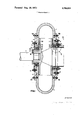
- FIG. I an axial section through a preferred embodiment of a centrifugal pump according to the invention
- FIGS. 2a and 2b on larger scales each the detail II of FIG. I in various positions of the seal
- FIG. 3 on a larger scale the detail III of FIG. I,
- FIG. 4 a longitudinal section of a detail of another centrifugal pump according to the invention having a seal with cilindrical faces
- FIG. 5 a section over the line V-V OF FIG. 4,
- FIG. 6 a longitudinal section of a detail of a known centrifugal pump having a conventional seal with a cilindrical face
- FIGS. 7a and 7b each a schematic view of the equilibrium of forces of the sealing ring of FIG. 6 in two different positions
- FIGS. 8a and 8b each a schematic view of a sealing ring for a centrifugal pump according to the invention with the equilibrium of forces concerning the sealing ring of detail III, in two different positions,
- FIG. 9 a schematic view corresponding with FIG. 8b concerning another embodiment of a seal of a centrifugal pump according to the invention.
- FIGS. 10a and 10b each a schematic view of the equilibrium of forces exerted on the sealing ring of the positions of FIGS. 2a and 212 respectively.
- FIG. II a schematic view corresponding with FIG. 10b concerning another embodiment of a seal of a centrifugal pump according to the invention.
- the centrifugal pump according to the invention shown in FIG; 1, which is particularly adapted for pumping a suspension of sand and water, comprises a casing I and an impeller 2 driven by a shaft 3.
- a front cover 5 attached at the casing I by means of bolts 50, a rear cover 4 attached at the casing l-by means of bolts 50, a front flange 7 attached at said front cover 5 by means'of bolts 8 and a rear flange 11 at the rear cover 4 by means of bolts 8 and letting pass the shaft 3, constitute parts of the casing I.
- a supply line 6 is connected to the front flange 7..
- FIG. 3 the special sealing means III of the seal be tween impeller 2 and rear cover 4 are shown on large scale.
- Said sealing means comprise a guide collar 13 forming part of the rear flange 11 and a sealing ring 12 having a collar 51 mounted slidably in axial direction on the guide collar 13 and being sealed relatively to said guide collar 13 by means of an O-ring 52.
- the sealing ring 12 has two faces spaced from each other by a space 33, viz; a first face 32 positioned adjacent the exhaust zone of the pump and thus adjacent the highpressure zone of the sealing means and a second face 34 positioned adjacent the atmospheric pressure zone of the pump and thus adjacent the low-pressure zone of the sealing means.
- the faces 32 and 34 cooperate with co-acting face 53 and are actuated to abut it as a unit by the sum of the actuating forces, exerted on a first back surface 54 and a second back surface 55.
- the first back surface 54 is influenced by the high-pressure zone 56 and the second back surface 55 by the low-pressure zone 57.
- the high-pressure zone 56 is constituted by an annular space 56 communicating through an inlet 14 with a source of purgating water, having such high-pressure that it prevents the suspension of sand and water of reaching the sealing means through the gap 58 between impeller 2 and rear cover 4.
- the space 33 communicates with the zone 57 through a passage 59.
- the faces 32 and 34 are supplied with grease through grease supply 35 and connecting passages 30.
- FIG. 6 shows an impeller 62 provided with an annular ring 63 connected to the impeller 62 by means of bolts 65.
- the flange 67 having a collar 61 supports by means of bolts 60 a sealing ring 69 having a L-shaped longitudinal section.
- the high-pressure Pu would be decreased up to the lowpressure Pi along the first face 32 owing to the space 33 communicating with the high-pressure zone Pu through the gap between the first face 32 and the coacting face 53.
- This first face 32 is then actuated by a resultant pressure Pu Pi/2, whereas the second face 34 is actuated by the low-pressure Pi.
- the first back surface 54 of the sealing ring 12 is actuated by the highpressure Pu and the second back surface 55 by the low- I pressure Pi.
- the axial lengthes of the first back surface 54, the second back surface 55, the first face 32 and the second face 34 are so great relatively to each other, that the resultant of the actuating forces at the back surfaces 54 and 55 just exceeds the resultant of the forces on the faces 32 and 34 when the sealing ring 12 might be free from the co-acting face 53 (FIG. 8a).
- the pressures Pu and Pi on the back surfaces 54 and 55 press the sealing ring against the impeller 2, resulting in a specific face surface pressure Pv on the faces 32 and 34.
- Comparison with FIG. 7b shows clearly that the specific face surface pressure Pv of FIG. 8b is appreciable lower, resulting in a decreased wear.
- the specific face surface pressure Pv is further reduced, owing to the first back surface 70 being smaller than the first back surface 54 of FIGS. 8a and 8b.
- the area of the first back surface 70 is preferably so determined that the total actuating forces on the first and second back surfaces just exceed the sum of the forces on the faces 32 and 34.
- the sealing means of the seal II of the centrif ugal pump of FIG. 1 comprise a guide collar 9 forming part of the front flange 7 and a sealing ring 10 having collars 16 and 49 engaging the guide collar 9 slidably in axial direction and being sealed by means of O-rings 39.
- the sealing ring 10 has two faces spaced from each other by means of a space 18, viz.
- the faces 17 and 19 cooperate with co-acting face 45 and are actuated as a unit against it by the sum of the actuating forces exerted on a first back surface 27, a second back surface 29 and on a third back surface 28 influenced by the high-pressure Pu, the low-pressure Pi and control pressure Pr of a control space 24 respectively.
- the sec end face 19 communicates with the control space 24 through passages 23.
- the control space 24 communicates through throttle means 25 and a passage 26 with a control pressure source, for instance atmosphere. Collars l6 and 49 support the first and second back surfaces 27 and 29.
- the wall 28 of the control space 24 constitutes the third back surface 28.
- the space 18 communicates with the low-pressure zone through passages 22.
- the faces 17, 19, 32 and 34 consist of linings 21, 20, 73 and 74 respectively of wear resistant rubber like material.
- the high-pressure zone adjacent the sealing ring 10 communicates through inlet 15 with said source of purgating water.
- FIGS. 4 and 5 a radial seal for a centrifugal pump according to the invention is shownsAn annular ring 76 is attached at the impeller 2 by means of bolts 75.
- front flange 7 supports rings 37 and 48 connected to each other free of leakage by means of packings 46 and 47.
- the control space 24 communicates through passage 26 and throttle means 25 formed by a narrow opening with the control pressure source, for instance atmosphere 70.
- a first face 43 is spaced from a second face 44 by means of a space 42 communicating with inlet pressure Pi through passages 41.
- the faces 43 and 44 consist of wear proof rubberlike material vulcanised on the sealing ring elements 77.
- Said sealing ring elements 77 constitute together with said rubberlike material an annular sealing ring with cilindrical faces 43 and 44.
- the face 44 communicates with the control space -24 through passages 40. Due to this construction of the sealing ring it may expand for adaption to possible irregular operation, while a contact of the faces 43 and '44 with a low specific face surface pressure Pv according to the invention is assured.
- a centrifugal pump comprising a casing, at least one impeller mounted for rotation in said casing and at least one seal for limiting leakage between the rotating impeller and the casing, said seal having sealing means with at least two faces spaced from each other by a space, a first of said faces being positioned adjacent a highpressure zone and a second of said faces being positioned adjacent a lowpressure zone, said faces forming part of one and the same sealing ring movable transversely to said faces, and said sealing ring having at least one back surface influenced by the pressure of said high pressure zone and at least one back surface influenced by the pressure of said lowpressure zone,
- said space communicating with a region of pressure considerably lower than the pressure of said high pressure zone.
- a centrifugal pump as claimed in claim I characterised in that said second face communicates with a control space separated from the low-pressure zone, said control space communicating via throttle means with a control pressure source, said sealing ring having a third back surface influenced by the control pressure of the control space.
- a centrifugal pump as claimed in claim ll characterised in that said space communicates with said low pressure zone.
- a centrifugal pump having a casing and an impeller mounted for rotation in said casing, said impeller including a seal-engageable face leading transversely thereof from a high pressure region of said pump to a low pressure region, and a sealing ring movably carried by said casing for movement toward and away from said seal-engageable face, said sealing ring comprising:
- a body having a pair of annular faces facing and adapted to engage said seal-engageable face of the impeller, said annular faces being separated by a channel, said body having a pair of rear faces opposite to and parallel with said annular faces, one of said rear faces being exposed to said high pressure region and the other of said rear faces being exposed to said low pressure region;
- seal means engaging said body between said rear faces thereof for pressure isolating said rear faces from each other;
- sealing means interposed between the casing and the impeller and movably carried by one of them for movement normal to the direction in which fluid tends to leak into engagement with the other of said casing and impeller, said sealing means comprising:
- annular member surrounding said impeller and having a pair of annular faces adapted to engage said other of said casing and impeller, recess means separating said annular faces for defining a bottom wall area of first selected area, said member having a pair of rear faces opposite from said annular faces one of which is of second selected area and the other of which is of third selected area, said one rear face communicating with a high pressure region in said pump and said other rear face comm unicating with a low pressure region;
- seal means for isolating said rear faces from each other
- said first, second and third selected areas being balanced with respect to the pressures acting on them to establish a low residual sealing force pressing said annular faces against said other of said casing and impeller preventing said leakage of fluid past said impeller.
- a centrifugal pump having a casing and an impeller rotatably mounted in said casing whereby to generate a fluid high pressure region within said casing which tends to leak fluid past said impeller, and sealing means for preventing such leakage, said impeller having an annular surface across which fluid tends to leak and cooperating with said sealing means and said sealing means being movably carried by said casing for movement perpendicular to such surface into and out of engagement therewith, said sealing means comprismg:
- a ring having a pair of annular surfaces opposed to said annular surface of the impeller, one of which is disposed on a high fluid pressure side of the sealing means and the other of which is disposed on a low fluid pressure side of the sealing means;
- recess means separating said annular surfaces for decated thereby imposing but little force tending to separate said sealing means from said annular surface of the impeller;
- said sealing ring having a pair of rear faces opposite from said annular faces, one of said rear faces being continuously exposed to high fluid pressure and the other of said rear faces being continuously exposed to low fluid pressure;
- seal means engaging said sealing ring for pressure isolating said rear faces from each other;
- the areas of said rear faces being such as tends always to override any separating force between the annular surface of the impeller and said sealing means while producing a low residual force pressing said annular faces against said annular surface of the impeller.
- a centrifugal pump as defined in claim 17 including a third rear face on said sealing ring between the first two mentioned rear faces, said seal means pressure isolating all of said rear faces from each other; and means communicating said third rear face with a source of control pressure.
Landscapes
- Engineering & Computer Science (AREA)
- General Engineering & Computer Science (AREA)
- Mechanical Engineering (AREA)
- Structures Of Non-Positive Displacement Pumps (AREA)
- Sealing Devices (AREA)
Applications Claiming Priority (1)
| Application Number | Priority Date | Filing Date | Title |
|---|---|---|---|
| NL7011545.A NL157081B (nl) | 1970-08-04 | 1970-08-04 | Afdichting voor het afdichten van een spleet tussen een stationair en een roteerbaar onderdeel. |
Publications (1)
| Publication Number | Publication Date |
|---|---|
| US3754834A true US3754834A (en) | 1973-08-28 |
Family
ID=19810716
Family Applications (1)
| Application Number | Title | Priority Date | Filing Date |
|---|---|---|---|
| US00167674A Expired - Lifetime US3754834A (en) | 1970-08-04 | 1971-07-30 | Centrifugal pump |
Country Status (6)
| Country | Link |
|---|---|
| US (1) | US3754834A (enExample) |
| JP (1) | JPS5427561B1 (enExample) |
| BE (1) | BE770836A (enExample) |
| FR (1) | FR2101970A5 (enExample) |
| GB (1) | GB1361987A (enExample) |
| NL (2) | NL157081B (enExample) |
Cited By (13)
| Publication number | Priority date | Publication date | Assignee | Title |
|---|---|---|---|---|
| US4101241A (en) * | 1976-05-19 | 1978-07-18 | Kabushiki Kaisha Komatsu Seisakusho | Super charger with fluid biased heat shroud |
| US4334830A (en) * | 1980-03-24 | 1982-06-15 | The Nash Engineering Company | Two-stage liquid ring pump with improved intrastage and interstage sealing means |
| US4802818A (en) * | 1987-09-28 | 1989-02-07 | Daniel Wiggins | Slurry pump suction side liner with replaceable components |
| US5179881A (en) * | 1991-04-23 | 1993-01-19 | Mccain Foods Limited | System for producing helical vegetable strips and turbine therefor |
| US5284347A (en) * | 1991-03-25 | 1994-02-08 | General Electric Company | Gas bearing sealing means |
| US5971704A (en) * | 1997-04-23 | 1999-10-26 | Toyo Pumps North America Corporation | Device for adjusting the running clearance of an impeller |
| RU2191296C1 (ru) * | 2001-02-05 | 2002-10-20 | Тюменский государственный нефтегазовый университет | Уплотнение вращающихся частей центробежного насоса |
| US20030012642A1 (en) * | 2001-07-03 | 2003-01-16 | Soja Marc S. C. | Adjustable pump wear plate positioning assembly |
| US20040255917A1 (en) * | 2003-06-20 | 2004-12-23 | Mokry Peter G. | Impeller and a supercharger for an internal combustion engine |
| WO2011086382A1 (en) | 2010-01-16 | 2011-07-21 | Nanoridge Materials, Incorporated | Ceramic matrix composite articles comprising graphene nanoribbons - like material and their manufacturing method using carbon nanotubes |
| CN103857917A (zh) * | 2011-10-07 | 2014-06-11 | 乌韦·维迪希 | 用于包含固体物质的液体的离心泵和缝隙密封装置 |
| CN106989051A (zh) * | 2017-05-19 | 2017-07-28 | 合肥工业大学 | 一种用于离心泵的密封口环 |
| US20200063747A1 (en) * | 2016-03-18 | 2020-02-27 | Weir Slurry Group, Inc. | Sealing Arrangement For Adjustable Elements Of A Pump |
Families Citing this family (1)
| Publication number | Priority date | Publication date | Assignee | Title |
|---|---|---|---|---|
| CN116792334B (zh) * | 2023-06-08 | 2025-11-25 | 福建泉昇水泵有限公司 | 一种叶轮进水段口环密封装置 |
-
1970
- 1970-08-04 NL NL7011545.A patent/NL157081B/xx not_active IP Right Cessation
-
1971
- 1971-07-03 GB GB3650871A patent/GB1361987A/en not_active Expired
- 1971-07-30 US US00167674A patent/US3754834A/en not_active Expired - Lifetime
- 1971-07-30 FR FR7128028A patent/FR2101970A5/fr not_active Expired
- 1971-07-31 JP JP5789171A patent/JPS5427561B1/ja active Pending
- 1971-08-02 BE BE770836A patent/BE770836A/xx unknown
-
1978
- 1978-04-24 NL NL7804357.A patent/NL159759B/xx not_active IP Right Cessation
Cited By (17)
| Publication number | Priority date | Publication date | Assignee | Title |
|---|---|---|---|---|
| US4101241A (en) * | 1976-05-19 | 1978-07-18 | Kabushiki Kaisha Komatsu Seisakusho | Super charger with fluid biased heat shroud |
| US4334830A (en) * | 1980-03-24 | 1982-06-15 | The Nash Engineering Company | Two-stage liquid ring pump with improved intrastage and interstage sealing means |
| US4802818A (en) * | 1987-09-28 | 1989-02-07 | Daniel Wiggins | Slurry pump suction side liner with replaceable components |
| US5284347A (en) * | 1991-03-25 | 1994-02-08 | General Electric Company | Gas bearing sealing means |
| US5179881A (en) * | 1991-04-23 | 1993-01-19 | Mccain Foods Limited | System for producing helical vegetable strips and turbine therefor |
| US5971704A (en) * | 1997-04-23 | 1999-10-26 | Toyo Pumps North America Corporation | Device for adjusting the running clearance of an impeller |
| RU2191296C1 (ru) * | 2001-02-05 | 2002-10-20 | Тюменский государственный нефтегазовый университет | Уплотнение вращающихся частей центробежного насоса |
| US6599086B2 (en) * | 2001-07-03 | 2003-07-29 | Marc S. C. Soja | Adjustable pump wear plate positioning assembly |
| US20030012642A1 (en) * | 2001-07-03 | 2003-01-16 | Soja Marc S. C. | Adjustable pump wear plate positioning assembly |
| US20040255917A1 (en) * | 2003-06-20 | 2004-12-23 | Mokry Peter G. | Impeller and a supercharger for an internal combustion engine |
| US7146971B2 (en) | 2003-06-20 | 2006-12-12 | Mokry Peter G | Impeller and a supercharger for an internal combustion engine |
| WO2011086382A1 (en) | 2010-01-16 | 2011-07-21 | Nanoridge Materials, Incorporated | Ceramic matrix composite articles comprising graphene nanoribbons - like material and their manufacturing method using carbon nanotubes |
| CN103857917A (zh) * | 2011-10-07 | 2014-06-11 | 乌韦·维迪希 | 用于包含固体物质的液体的离心泵和缝隙密封装置 |
| US20200063747A1 (en) * | 2016-03-18 | 2020-02-27 | Weir Slurry Group, Inc. | Sealing Arrangement For Adjustable Elements Of A Pump |
| US10895265B2 (en) * | 2016-03-18 | 2021-01-19 | Weir Slurry Group, Inc. | Sealing arrangement for adjustable elements of a pump |
| CN106989051A (zh) * | 2017-05-19 | 2017-07-28 | 合肥工业大学 | 一种用于离心泵的密封口环 |
| CN106989051B (zh) * | 2017-05-19 | 2023-05-12 | 合肥工业大学 | 一种用于离心泵的密封口环 |
Also Published As
| Publication number | Publication date |
|---|---|
| NL7804357A (nl) | 1978-09-29 |
| DE2138836A1 (de) | 1972-07-13 |
| NL159759B (nl) | 1979-03-15 |
| GB1361987A (en) | 1974-07-30 |
| FR2101970A5 (enExample) | 1972-03-31 |
| NL7011545A (enExample) | 1972-02-08 |
| NL157081B (nl) | 1978-06-15 |
| JPS5427561B1 (enExample) | 1979-09-11 |
| BE770836A (fr) | 1972-02-02 |
| DE2138836B2 (de) | 1975-08-07 |
Similar Documents
| Publication | Publication Date | Title |
|---|---|---|
| US3754834A (en) | Centrifugal pump | |
| US3632117A (en) | Seal lift-off mechanism | |
| US3137238A (en) | Pump or motor | |
| US3975123A (en) | Shaft seals for a screw compressor | |
| US5141389A (en) | Control system for regulating the axial loading of a rotor of a fluid machine | |
| US4993917A (en) | Gas compressor having dry gas seals | |
| US3068801A (en) | Centrifugal impeller pumps | |
| US2824522A (en) | Pump, pressure loaded with offset loading | |
| US3179422A (en) | Self-compensating shaft seal | |
| GB2044369A (en) | Hydrostatic shaft seal | |
| US2221225A (en) | Balancing and leakage device for centrifugal pumps | |
| US3062554A (en) | Rotary shaft seal | |
| US3033577A (en) | Oil seal | |
| US4460180A (en) | Sealing of a shaft in a centrifugal pump and a method for effecting the sealing | |
| US4632402A (en) | Shaft seal with both hydrostatic and hydrodynamic pressure parts | |
| US5072949A (en) | Liquid-flushed seal for rotating shaft with vacuum providing leakage controlling choke in flushing liquid supply conduit | |
| US3652180A (en) | Centrifugal pump and seal means therefore | |
| US2297302A (en) | Sealing device | |
| US3122374A (en) | Seal for rotating shaft with pressure responsive means | |
| US2698584A (en) | Centrifugal pump | |
| US2590561A (en) | Screw pump | |
| US3533635A (en) | Pressure controlled shaft seal injection system | |
| EP0167837B1 (en) | Seal device for interposition between a pump body and pump impeller | |
| US1837873A (en) | Centrifugal pump | |
| US4224008A (en) | Volute slurry pump and throttle bushing therefor |