US3750157A - Light detection monitoring device - Google Patents
Light detection monitoring device Download PDFInfo
- Publication number
- US3750157A US3750157A US00138905A US3750157DA US3750157A US 3750157 A US3750157 A US 3750157A US 00138905 A US00138905 A US 00138905A US 3750157D A US3750157D A US 3750157DA US 3750157 A US3750157 A US 3750157A
- Authority
- US
- United States
- Prior art keywords
- tube
- alarm
- means comprises
- high frequency
- responsive
- Prior art date
- Legal status (The legal status is an assumption and is not a legal conclusion. Google has not performed a legal analysis and makes no representation as to the accuracy of the status listed.)
- Expired - Lifetime
Links
- 238000001514 detection method Methods 0.000 title claims abstract description 14
- 238000012806 monitoring device Methods 0.000 title abstract description 20
- 230000000903 blocking effect Effects 0.000 claims abstract description 12
- 230000001186 cumulative effect Effects 0.000 claims abstract description 5
- 230000000694 effects Effects 0.000 claims abstract description 5
- 230000001953 sensory effect Effects 0.000 claims description 11
- 238000012544 monitoring process Methods 0.000 claims description 6
- 230000000737 periodic effect Effects 0.000 claims description 2
- 230000004044 response Effects 0.000 claims description 2
- 208000028659 discharge Diseases 0.000 description 35
- 239000007789 gas Substances 0.000 description 14
- 238000004804 winding Methods 0.000 description 8
- 230000010355 oscillation Effects 0.000 description 7
- 238000010586 diagram Methods 0.000 description 6
- 230000004907 flux Effects 0.000 description 4
- 150000002500 ions Chemical class 0.000 description 4
- 230000035945 sensitivity Effects 0.000 description 4
- 230000005540 biological transmission Effects 0.000 description 3
- 239000003990 capacitor Substances 0.000 description 3
- 230000008878 coupling Effects 0.000 description 3
- 238000010168 coupling process Methods 0.000 description 3
- 238000005859 coupling reaction Methods 0.000 description 3
- 230000005684 electric field Effects 0.000 description 3
- 238000005286 illumination Methods 0.000 description 3
- XKRFYHLGVUSROY-UHFFFAOYSA-N Argon Chemical compound [Ar] XKRFYHLGVUSROY-UHFFFAOYSA-N 0.000 description 2
- 238000006243 chemical reaction Methods 0.000 description 2
- 239000004020 conductor Substances 0.000 description 2
- 239000011261 inert gas Substances 0.000 description 2
- 238000009434 installation Methods 0.000 description 2
- 238000012986 modification Methods 0.000 description 2
- 230000004048 modification Effects 0.000 description 2
- 229910052754 neon Inorganic materials 0.000 description 2
- GKAOGPIIYCISHV-UHFFFAOYSA-N neon atom Chemical compound [Ne] GKAOGPIIYCISHV-UHFFFAOYSA-N 0.000 description 2
- 244000045947 parasite Species 0.000 description 2
- 239000002245 particle Substances 0.000 description 2
- 230000002441 reversible effect Effects 0.000 description 2
- 229910052724 xenon Inorganic materials 0.000 description 2
- FHNFHKCVQCLJFQ-UHFFFAOYSA-N xenon atom Chemical compound [Xe] FHNFHKCVQCLJFQ-UHFFFAOYSA-N 0.000 description 2
- WUPHOULIZUERAE-UHFFFAOYSA-N 3-(oxolan-2-yl)propanoic acid Chemical compound OC(=O)CCC1CCCO1 WUPHOULIZUERAE-UHFFFAOYSA-N 0.000 description 1
- AANMVENRNJYEMK-UHFFFAOYSA-N 4-propan-2-ylcyclohex-2-en-1-one Chemical compound CC(C)C1CCC(=O)C=C1 AANMVENRNJYEMK-UHFFFAOYSA-N 0.000 description 1
- BUGBHKTXTAQXES-UHFFFAOYSA-N Selenium Chemical compound [Se] BUGBHKTXTAQXES-UHFFFAOYSA-N 0.000 description 1
- XUIMIQQOPSSXEZ-UHFFFAOYSA-N Silicon Chemical compound [Si] XUIMIQQOPSSXEZ-UHFFFAOYSA-N 0.000 description 1
- 241000269400 Sirenidae Species 0.000 description 1
- 229910052786 argon Inorganic materials 0.000 description 1
- 230000015572 biosynthetic process Effects 0.000 description 1
- 229940116367 cadmium sulfide Drugs 0.000 description 1
- 229910052980 cadmium sulfide Inorganic materials 0.000 description 1
- 230000000295 complement effect Effects 0.000 description 1
- 230000003247 decreasing effect Effects 0.000 description 1
- 229910052734 helium Inorganic materials 0.000 description 1
- 239000001307 helium Substances 0.000 description 1
- SWQJXJOGLNCZEY-UHFFFAOYSA-N helium atom Chemical compound [He] SWQJXJOGLNCZEY-UHFFFAOYSA-N 0.000 description 1
- 230000003993 interaction Effects 0.000 description 1
- 230000002452 interceptive effect Effects 0.000 description 1
- 230000002045 lasting effect Effects 0.000 description 1
- 239000000203 mixture Substances 0.000 description 1
- 230000007935 neutral effect Effects 0.000 description 1
- 230000003287 optical effect Effects 0.000 description 1
- 230000002265 prevention Effects 0.000 description 1
- 230000005855 radiation Effects 0.000 description 1
- 230000006798 recombination Effects 0.000 description 1
- 238000005215 recombination Methods 0.000 description 1
- 235000002020 sage Nutrition 0.000 description 1
- 229910052711 selenium Inorganic materials 0.000 description 1
- 239000011669 selenium Substances 0.000 description 1
- 230000008054 signal transmission Effects 0.000 description 1
- 230000011664 signaling Effects 0.000 description 1
- 229910052710 silicon Inorganic materials 0.000 description 1
- 239000010703 silicon Substances 0.000 description 1
- 230000002269 spontaneous effect Effects 0.000 description 1
- 230000000007 visual effect Effects 0.000 description 1
Images

Classifications
-
- G—PHYSICS
- G08—SIGNALLING
- G08B—SIGNALLING OR CALLING SYSTEMS; ORDER TELEGRAPHS; ALARM SYSTEMS
- G08B13/00—Burglar, theft or intruder alarms
- G08B13/18—Actuation by interference with heat, light, or radiation of shorter wavelength; Actuation by intruding sources of heat, light, or radiation of shorter wavelength
- G08B13/189—Actuation by interference with heat, light, or radiation of shorter wavelength; Actuation by intruding sources of heat, light, or radiation of shorter wavelength using passive radiation detection systems
-
- G—PHYSICS
- G08—SIGNALLING
- G08B—SIGNALLING OR CALLING SYSTEMS; ORDER TELEGRAPHS; ALARM SYSTEMS
- G08B17/00—Fire alarms; Alarms responsive to explosion
- G08B17/12—Actuation by presence of radiation or particles, e.g. of infrared radiation or of ions
Definitions
- a light detection monitoring device includes a gaseous [58] Field of Search 340/2281, 228.2, discharge tube for converting incident light into an 213 R electric signal, and a blocking oscillator.
- the oscillator which is coupled to one of the electrodes of the tube [56] References Cited and is enabled by the electric signal produced by the UNITED STATES PATENTS discharge tube, supplies short pulses which add to the 3 3 244 4/1967 Voight 340/227 R discharge current to effect cumulative ionization of the 3:416:04 12/1963 G iff id 340/227 R X gas in the tube and the attendant generation of high fre- 3,544,792 12/1970 Giltaire 340/227 x quency waves.
- the increased discharge current and the 3,683,372 8/1972 Horn 340/227 X high frequency waves are then employed to trigger 2,556,961 1951 Feigal 340/2231 X local and remote alarm devices, respectively.
- the present invention relates to monitoring devices and, more particularly, to a new and improved monitoring device employing a discharge tube as a photosensitive element for producing a distinctive signal when a beam of light illuminates the tube.
- the field of monitoring devices for human and property protection is highly developed and complex.
- One type of monitoring device with which the present invention is related employs a light detector to trigger circuitry for sounding an alarm when the detector is sub jected to light.
- the light detectors now in widespread use will not respond satisfactorily to an incident luminous flux of low intensity.
- the sensitivity of the class of photoconductive detectors such as cad mium sulfide and selenium cells is limited by the significant intensity of their darkness current, as well as by the low frequency intrinsic noise accompanying pas sage of electrons from the valence band to the conduction band.
- cathode emission detectors such as vacuum or gas cells
- photomultipliers Several factors tend to limit the sensitivity of these detectors. The most significant factors are the statistical character of the electronic flux of cathode emission or secondary emission, the spontaneous emission of parasite electrons not caused by the light signal, and the wide low frequency fluctuations in the supply source, which in the case of photomultipliers, can extend to several milliamperes.
- glow tubes for light detection, as well as for signal transmission.
- the sensitivity of these tubes is limited by fluctuations in cathode drop and potential difference at the terminals and by the comparatively high darkness current maintained by a steadily applied internal electric source.
- the present invention provides a combination of a photosensitive member and a complementary electronic accessory. More specifically, by the novel employment of the special properties of ionized gases in a discharge tube, and the ability of such tubes to generate high frequency oscillations, the device according to the present invention provides a powerful signal even when the incident light intensity is very low. In addition, the device, being free from low frequency fluctuations, remains inoperative both in the absence of illumination and when the tube is short-circuited.
- the photosensitive member comprises a gas that readily absorbs photons of light, provides a very low detection threshold, and under suitable conditions of installation, generates and sustains high frequency oscillations.
- the small electric current supplied by the photosensitive member when illuminated acts upon the electronic accessory which, after processing the signal, reapplies the processed signal to the photosensitive member.
- the photosensitive member then transmits the resulting discharge current to following stages to sound an alarm.
- the photosensitive member utilized in the present invention performs three salient functions: (1) the conversion of incident light quanta into a weak electric current, (2) the reception of the signals processed by the electronic accessory, and (3) the transmission of either its discharge current or the high frequency electromagnetic energy produced therein to sound an alarm.
- the photosensitive member does not operate with an outside source and, accordingly, is not subjected to low frequency parasite fluctuations.
- the present invention provides both a very low light detection threshold and a very high light-to-electric-signal conversion slope.
- the combination serves as a high frequency emitter modulated at the frequency determined by the accessory.
- the monitoring device comprises in combination a photosensitive gas element and an active electronic acces sory consisting of passive elements.
- the gas element comprises a bidirectionally conductive tube having two like cold electrodes free from continuous interference by an outside source and filled with a pure inert gas or mixture of gases, preferably a monatomic gas, such as neon, argon, helium, crypton or xenon.
- the electronic accessory comprises a blocking oscillator coupled to one electrode of the photosensitive element.
- the other electrode when the tube is operated in closed circuit, is connected through a detector to a sensory alarm indicator.
- the other electrode of the tube is connected to a radio frequency antenna which radiates the high frequency waves produced in the tube.
- the monitoring device of the present invention is especially useful for fire detection, burglary prevention, alarm or control systems actuated at a distance by a beam of light and the detection of the establishment of an arc in an inaccessible high-tension installation.
- the monitoring device of the present invention may respond to lasting or transitory illumination of the discharge tube through acoustic means, such as gongs, sirens, loudspeakers, or visual means such as lighting of an incandescent lamp, deviation of a pointer, production of a recording, or in any other manner suited to the particular conditions of service.
- the novel means according to the invention will likewise serve to provide an uninterrupted warning signal requiring manual intervention to stop the alarm.
- the device is compact and light weight and can be installed easily as required for varied applications.
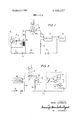
- FIG. 1 is a schematic block diagram of the basic embodiment of a monitoring device arranged according to the present invention
- FIG. 2 is a schematic block diagram of a closed circuit embodiment of the present invention which provides an alarm of limited duration
- FIG. 3 is a schematic circuit diagram of a closed circuit embodiment of the present invention that provides a warning signal of extended duration
- FIG. 4 is a schematic block diagram of an open circuit embodiment of the present invention that provides high frequency radiation.
- FIG. 5 is a schematic block diagram of an open circuit embodiment of the present invention that provides an uninterrupted alarm signal.
- the device includes a gaseous discharge tube such as, for example, a neon or xenon tube. Ionization of the gases within the tube 10 is initiated when the tube is illuminated by a beam of light 12.
- a gaseous discharge tube such as, for example, a neon or xenon tube. Ionization of the gases within the tube 10 is initiated when the tube is illuminated by a beam of light 12.
- One electrode 10a of the tube 10 is coupled via a conductor 14 and its branch conductor 14a to the collector of a transistor 16 forming an integral part of blocking oscillator 18 and to the primary winding of a transformer 20 also forming an integral part of the oscillator 18.
- the oppositely poled output or secondary winding of the transformer 20 is coupled across the base and cathode of the transistor 16 through a resistor 22 and a capacitor 24.
- a normally closed switch 26 which couples an enabling DC source E1 concurrently to the cathode of the transistor 16 and to the output winding of the transformer 20.
- the negative terminal of the source E1 is connected to the primary winding of the transformer 20 and through a normally closed switch 28 to a second normally closed switch 30 and a second DC source E2.
- the two DC sources E1 and E2 preferably supply equal voltage potentials.
- the other electrode 10b of the tube 10 is connected to the output circuitry of the device.
- the output circuitry includes a detector-amplifier 32 that is enabled by the DC source E2 through the switch 30.
- An alarm circuit 34 completes the output circuitry of the monitoring device and is enabled by the DC source E2 and is driven into operation to generate an alarm by the amplifier 32.
- the alarm 34 may be located either locally with the discharge tube 10 or remotely therefrom.
- the switches 26 and 30 enable the operation of the input and output circuitry, respectively, and that the switch 28 serves the function of either coupling or isolating the input and output circuitry of the device.
- the device will energize the alarm 34 as long as the tube 10 is illuminated by teh optical electromagnetic energy 12.
- the blocking oscillator 18 and the amplifier 32 are in their quiescent states.
- the input and output windings of the transformer 20 are not acted upon by any current from the discharge tube 10 whose electrodes 10a and 10b are at the same potential. It necessarily follows that the collector current lc of the transistor 16 is zero. 4
- the photons of light absorbed by the inert gas of the tube 10 cause the formation of plasma in which neutral atoms, excited atoms, electrons and positive ions coexist.
- the electrified particles of the plasma wander in the interelectrode space, with some electrons reaching the electrode 10a and charging it negatively.
- a discharge current Ip is created in the primary winding of the transformer 20 which, in turn, induces a current Is in the secondary winding of the transformer.
- the capacitor 24 discharges through the resistor 22 to reduce the potential of the base of the transistor 16 until the transistor 16 starts to draw col lector current 10 and the collector voltage drops.
- the collector current Ic adds to the discharge current lp with the result that the potential of the electrode 10a is decreased.
- An electric field is established in the tube 10 which increases the collisions between electrons and atoms within the tube.
- the currents lp, Ic, ls grow in step with the potential difference across the tube 10 to effect cumulative ionization in the tube and the attendant generation of high frequency waves.
- a cloud of positive ions forms and increases around the electrode 10b to attract electrons and thereby reduce the number of electrons reaching the electrode 10a.
- the electric field, as well as the currents lc and lp, will then be reduced.
- the directions of the currents are reversed, and a secondary discharge current lb in the output circuit is produced.
- the discharge current Ib drives the detector-amplifier 32 into conduction which, in turn, drives the alarm circuit 34 to generate a sensory alarm indication.
- the capacitor 24 of the blocking oscillator charges to reverse bias the transistor 16.
- the positive ions collect at electrode 10a to diminish the reverse electric field and the cycle repeats itself for as long as the discharge tube 10 remains illuminated.
- the timing is maintained by the discharge tube 10.
- the critical features of the present invention are the interdependence of the blocking oscillator 18 and the discharge tube 10, the monatomic gas of the tube 10 and the omission of any permanent triggering source for the tube 10.
- FIG. 2 there is shown a closed circuit monitoring device of the type illustrated in FIG. 1, with the exception that one form of amplifier 32 is diagrammatically illustrated and several alarm indicators which may be used as the local alarm 34 are illustrated.
- the amplifier 32 is shown as including a pnp transistor 36 and the alarm circuit 34 is shown as including a stepping switch 28 for coupling the collector of the transistor 36 to either a loudspeaker 40, a meter 42 or a light bulb 44. It will be understood that in actual practice only one of the alarms 40, 42 and 44 would be coupled directly to the output of the amplifier 32 and any particular location.
- the amplifier 32 includes a silicon thyristor 46 having its control electrode coupled to the electrode 10b of the discharge tube 10.
- a signal, even a brief one, furnished by electrode 10b triggers the thyristor 46 which will then supply a continuous current It to the alarm circuit 34 which may comprise for example, an incandescent bulb, a pointer instrument, an acoustic alarm or any other constant current signaling device.
- An additional switch d8 serves to stop the current It to the alarm circuit 341.
- a thyratron may be used in place of the thyristor 46 to produce a constant warning signal, as will be understood in the art.
- FIG. 4 illustrates an open circuit embodiment of the present invention which radiates high frequency waves into the surrounding space.
- An antenna 50 which may consist of a single wire, is connected to electrode 10b of the discharge tube It Since the potentials of electrodes ltla and 10b are not fixed.
- the ionized particles wander from one electrode to the other, undergoing collisions, recombinations and reionizations. These frequent interactions, as well as the dislocations of the positive ions, produce a band of high frequency waves modulated by the low frequency oscillations of the blocked oscillator 18.
- the waves generated fall within the band of conventional radio frequencies.
- a remotely located radio receiver 52 having an antenna will detect these waves generated by the discharge tube 10 and make the vibrations of the blocked oscillator 18 audible through its speaker.
- a second transformer 54 is interposed between the transformer 20 operating the oscillator 18 (FIG. ii) and electrode 10a. The primary windings of transformers 54 and 20 are connected in parallel.
- the antenna 50 may be long, so thatthe receiver 52 may be placed at a very great distance and, more specifically, in a different location from that of the monitoring device. It is possible, however, to place the tube 10 and the oscillator 1% inside the cabinet of receiver 52 without interfering in any way with normal radio operation. To listen to ordinary voice transmission, the discharge tube 10 need merely be short-circuited with a switch 56, thereby eliminating the monitoring mode.
- FIG. 5 An open circuit embodiment of the present invention that provides an uninterrupted signal is schematically shown in FIG. 5.
- the connection between the oscillator 18 and the transformer 54 leading to electrode 10a of discharge tube It) is the same as in FIG. 4.
- a thyristor 58 located inside a radio receiver 52, is inserted between the positive terminal of a supply source 153 and the positive tab of a supply bar 59 which, when energized, supplies current to the radio circuitry (not shown).
- the electrode 10b of the discharge tube 10 is connected directly to the control electrode of the thyristor 58, the emitter of which is connected to the positive terminal of the source E3 and the collector which supplies the positive tab of the bar 59 of the receiver.
- the thyristor 58 serves as a switch, open in the absence of the luminous flux 112 and closed when the light appears. In order to generate a loud sound in case of intrusion, it is desirable to take the precaution of raising the volume control potentiometer 60 of the radio receiver all the way and setting the wavelength of the receiver to a powerful broadcast transmitter.
- a switch 62 connected between the collector and the emitter of the thyristor 58 serves to stop the thyristor, but off the receiver 52 and restore the monitoring mode of the device as a whole. In darkness, the receiver, having no supply, remains silent.
- the tube 10 in order not to render the tube It) conspicuous, the tube 10 may be covered by a filter.
- a filter In this embodiment, in order not to render the tube It) conspicuous, the tube 10 may be covered by a filter.
- monitoring is not required, normal radio listening modes may be restored. It then suffices to disconnect the wire coupling the electrode 10b to the control electrode of the thyristor 58 and make a direct connection joining the positive terminals of the source E3 and bar 59.
- a light detection monitoring system comprising a gaseous discharge tube filled with a monatomic gas for producing high frequency electromagnetic waves and a discharge current in the presence of light, signal generating means coupled to the gaseous discharge tube and responsive to the discharge current produced by the tube for generating periodic signals which add to the discharge signal to effect cumulative ionization of the gas in the tube and the reenforcement of the high frequency electromagnetic waves produced by the tube and means operatively coupled to the tube for producing a detectable alarm in response to the ionization of the gas within the discharge tube.
- the alarm producing means comprises means responsive to the discharge current for producing a sensory alarm.
- Apparatus according to claim 1 wherein the alarm producing means comprises means responsive to the high frequency electromagnetic energy for providing a sensory alarm indication.
- the alarm producing means comprises means for radiating the high frequency electromagnetic energy and radio receiver means tuned to the frequency of the radiated high frequency energy.
- the signal generating means comprises a blocking oscillator having a'transistor and a pulse transformer coupled across the terminals of the transistor and to one of the electrodes of the gaseous discharge device.
- the alarm producing means comprises an amplifier means responsive to the discharge current produced in the tube and a sensory alarm indicator responsive to the signals amplified by the detector amplifier for providing a sensory alarm indication.
- circuit energizing means comprises a source of potential, a receiver energizing supply bar and a thyristor coupled between the source and the supply bar and responsive to the high frequency electromagnetic energy produced by the tube for closing a circuit between the source and the supply bar to thereby energize the supply bar.
Landscapes
- Physics & Mathematics (AREA)
- General Physics & Mathematics (AREA)
- Business, Economics & Management (AREA)
- Emergency Management (AREA)
- Other Investigation Or Analysis Of Materials By Electrical Means (AREA)
- Emergency Alarm Devices (AREA)
Applications Claiming Priority (1)
| Application Number | Priority Date | Filing Date | Title |
|---|---|---|---|
| US13890571A | 1971-04-30 | 1971-04-30 |
Publications (1)
| Publication Number | Publication Date |
|---|---|
| US3750157A true US3750157A (en) | 1973-07-31 |
Family
ID=22484194
Family Applications (1)
| Application Number | Title | Priority Date | Filing Date |
|---|---|---|---|
| US00138905A Expired - Lifetime US3750157A (en) | 1971-04-30 | 1971-04-30 | Light detection monitoring device |
Country Status (3)
| Country | Link |
|---|---|
| US (1) | US3750157A (enExample) |
| DE (1) | DE2200085A1 (enExample) |
| FR (1) | FR2134570B1 (enExample) |
Families Citing this family (1)
| Publication number | Priority date | Publication date | Assignee | Title |
|---|---|---|---|---|
| DE8808212U1 (de) * | 1988-06-25 | 1988-08-11 | Asea Brown Boveri AG, 6800 Mannheim | Schaltungsanordnung für einen Störungsmelder |
Citations (10)
| Publication number | Priority date | Publication date | Assignee | Title |
|---|---|---|---|---|
| US2556961A (en) * | 1947-02-24 | 1951-06-12 | Honeywell Regulator Co | Flame detection apparatus |
| US3076897A (en) * | 1961-10-25 | 1963-02-05 | Clifford D Skirvin | Photoelectrically controlled transistor circuit |
| US3315244A (en) * | 1964-01-13 | 1967-04-18 | Aseco Inc | Alarm devices |
| US3416041A (en) * | 1965-09-02 | 1968-12-10 | Electronics Corp America | Flame sensor quench circuits for combustion control systems |
| US3544792A (en) * | 1967-12-08 | 1970-12-01 | Charbonnages De France | Ultraviolet flame detector using a trigger circuit to avoid false alarms |
| US3546692A (en) * | 1968-12-16 | 1970-12-08 | Chase Shawmut Co | Combined optical and acoustical blown fuse indicator |
| US3548395A (en) * | 1966-02-14 | 1970-12-15 | Combustion Eng | Flame condition sensing device |
| US3555532A (en) * | 1968-10-29 | 1971-01-12 | Graham Stuart Corp | Vapor or particle detection device |
| US3573777A (en) * | 1968-12-09 | 1971-04-06 | Honeywell Inc | Combustion products detector control apparatus |
| US3683372A (en) * | 1971-05-27 | 1972-08-08 | Robert Horn | Multimode self-checking flame detector |
-
1971
- 1971-04-30 US US00138905A patent/US3750157A/en not_active Expired - Lifetime
-
1972
- 1972-01-03 DE DE19722200085 patent/DE2200085A1/de active Pending
- 1972-04-27 FR FR7214978A patent/FR2134570B1/fr not_active Expired
Patent Citations (10)
| Publication number | Priority date | Publication date | Assignee | Title |
|---|---|---|---|---|
| US2556961A (en) * | 1947-02-24 | 1951-06-12 | Honeywell Regulator Co | Flame detection apparatus |
| US3076897A (en) * | 1961-10-25 | 1963-02-05 | Clifford D Skirvin | Photoelectrically controlled transistor circuit |
| US3315244A (en) * | 1964-01-13 | 1967-04-18 | Aseco Inc | Alarm devices |
| US3416041A (en) * | 1965-09-02 | 1968-12-10 | Electronics Corp America | Flame sensor quench circuits for combustion control systems |
| US3548395A (en) * | 1966-02-14 | 1970-12-15 | Combustion Eng | Flame condition sensing device |
| US3544792A (en) * | 1967-12-08 | 1970-12-01 | Charbonnages De France | Ultraviolet flame detector using a trigger circuit to avoid false alarms |
| US3555532A (en) * | 1968-10-29 | 1971-01-12 | Graham Stuart Corp | Vapor or particle detection device |
| US3573777A (en) * | 1968-12-09 | 1971-04-06 | Honeywell Inc | Combustion products detector control apparatus |
| US3546692A (en) * | 1968-12-16 | 1970-12-08 | Chase Shawmut Co | Combined optical and acoustical blown fuse indicator |
| US3683372A (en) * | 1971-05-27 | 1972-08-08 | Robert Horn | Multimode self-checking flame detector |
Also Published As
| Publication number | Publication date |
|---|---|
| FR2134570B1 (enExample) | 1975-10-24 |
| DE2200085A1 (de) | 1972-11-02 |
| FR2134570A1 (enExample) | 1972-12-08 |
Similar Documents
| Publication | Publication Date | Title |
|---|---|---|
| US3534351A (en) | Light coupled battery powered remote control apparatus | |
| US4099168A (en) | Intrusion alarm and emergency illumination apparatus and method | |
| US4091366A (en) | Sonic monitoring method and apparatus | |
| US4777474A (en) | Alarm system for the hearing impaired | |
| US3544987A (en) | Property protection alarm system | |
| US4092643A (en) | Security device | |
| US4612535A (en) | Add-on alert system | |
| US2709251A (en) | Audio electromagnetic capacity alarm device | |
| US4241332A (en) | Personal security alarm | |
| US4101880A (en) | Audiovisual signaling device | |
| US3683346A (en) | Variable-tone electronic alarm system | |
| US3786460A (en) | Light detection monitoring device | |
| US3750157A (en) | Light detection monitoring device | |
| US4287509A (en) | Sound and light signaling system | |
| GB888296A (en) | Improvements in or relating to electrical alarm systems | |
| US3205482A (en) | Emergency signal radio receiver responsive to cessation of all but the emergency frequency | |
| US3686655A (en) | Gas-alarming device | |
| US3573780A (en) | Automatic telephone alarm system | |
| US3391340A (en) | Alarm production over broadcasting channel by using long duration dissonant tones discordant with musical scale to prevent false actuation | |
| US3586919A (en) | Remote control device | |
| US3340521A (en) | Alarm system | |
| US3973250A (en) | Acoustically coupled burglar alarm system | |
| US3357009A (en) | Condition-responsive system for impressing distinctive frequency alarm tone on transmission line | |
| GB2032664A (en) | Electrical control apparatus | |
| US2608614A (en) | Signaling device |