US3748459A - Lamp for displaying variable shading and coloring effects and for general illumination - Google Patents
Lamp for displaying variable shading and coloring effects and for general illumination Download PDFInfo
- Publication number
- US3748459A US3748459A US00216967A US3748459DA US3748459A US 3748459 A US3748459 A US 3748459A US 00216967 A US00216967 A US 00216967A US 3748459D A US3748459D A US 3748459DA US 3748459 A US3748459 A US 3748459A
- Authority
- US
- United States
- Prior art keywords
- shade
- light source
- light
- lamp
- shading
- Prior art date
- Legal status (The legal status is an assumption and is not a legal conclusion. Google has not performed a legal analysis and makes no representation as to the accuracy of the status listed.)
- Expired - Lifetime
Links
Images
Classifications
-
- F—MECHANICAL ENGINEERING; LIGHTING; HEATING; WEAPONS; BLASTING
- F21—LIGHTING
- F21V—FUNCTIONAL FEATURES OR DETAILS OF LIGHTING DEVICES OR SYSTEMS THEREOF; STRUCTURAL COMBINATIONS OF LIGHTING DEVICES WITH OTHER ARTICLES, NOT OTHERWISE PROVIDED FOR
- F21V17/00—Fastening of component parts of lighting devices, e.g. shades, globes, refractors, reflectors, filters, screens, grids or protective cages
- F21V17/02—Fastening of component parts of lighting devices, e.g. shades, globes, refractors, reflectors, filters, screens, grids or protective cages with provision for adjustment
-
- F—MECHANICAL ENGINEERING; LIGHTING; HEATING; WEAPONS; BLASTING
- F21—LIGHTING
- F21V—FUNCTIONAL FEATURES OR DETAILS OF LIGHTING DEVICES OR SYSTEMS THEREOF; STRUCTURAL COMBINATIONS OF LIGHTING DEVICES WITH OTHER ARTICLES, NOT OTHERWISE PROVIDED FOR
- F21V11/00—Screens not covered by groups F21V1/00, F21V3/00, F21V7/00 or F21V9/00
- F21V11/16—Screens not covered by groups F21V1/00, F21V3/00, F21V7/00 or F21V9/00 using sheets without apertures, e.g. fixed
- F21V11/18—Screens not covered by groups F21V1/00, F21V3/00, F21V7/00 or F21V9/00 using sheets without apertures, e.g. fixed movable, e.g. flaps, slides
Definitions
- ABSTRACT A lamp comprising at least two light sources and shade components displaceable in relation to each other, whereby said shade components are arranged to affect the light emitted by one light source upon an outer shade component due to mutual displacement of said shade components in order to vary the shading or coloring effects or both on outer shade element.
- the present invention relates to a lamp which is adjustable to vary the shading or coloring effects or both on an outer shade.
- the lamp includes shade components movable with respect to each other and two or more light sources, and the invention relates in particular to a construction in which the light from at least one light source passes through one or more movable shade components to an outer shade component while the light of the other light sources is used substantially for illuminating the room.
- a purpose of the invention is to make a lamp adjustable with respect to shading and/or coloring effects more generally usable so that it is possible, besides making the lamp ornamental and one which is capable of varying shading and coloring effects, also to make the lamp efficient for illuminating the room independent of the position of the shading elements.
- the lamp according to the invention comprises one or more light sources, or there may be several light sources located so as to radiate light through the lamps shade components that are movable with respect to each other to one or more outer shade components, whereby the said light source in combination with the shade components makes it possible to adjust the lamps illumination and particularly its appearance.
- the purpose of the other light sources which may be one or more in number, is to illuminate the room in the conventional way without, however, affecting the shading and/or coloring produced by the former light source on the outer shade component. This is why it is preferably to provide these latter sources of light with shading in the direction of the outer shade, because they may easily, especially if they have a relatively high power, weaken the impression produced by the light source illuminating the outer shade component through the movable shade components.
- the invention is applicable to several lamp types and categories of lamps such as table, stand, wall and ceiling lamps, and to both indoor and outdoor lamps.
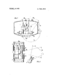
- FIG. 1 shows one embodiment of the invention.
- part of the light radiated by the light source 1 passes through partly movable shade 3 which is colored or has a pattern or both and through an opening 4b parallel with the circumference of the shade 4 to the outer shade 5 at an angle 6, while part of the light passes unfiltered out of shades 3 and 4 at angles 6b and 6c.
- the purpose of the light radiated by the light source 1 at angle 6 is to provide shading or coloring effects or both upon shade 5, which shading is determined by the position of the movable shade 3.
- the illumination of the light sources 2 is primarily at angles 9 and 9b and this illumination is shaded in the direction of angle 7 by shades 8. In this way, the filtered light is brought to part of the shade 5 and direct light from light source 2 to the shade sections 10 and 10b of shade 5.
- the shade 5 also receives the direct light of light source 1 whereby the lamp operates in the conventional way.
- the shade elements close to the light sources 1 and 2 of the lamp are shown in more detail.
- annular shade elements 4d and 40 have been installed outside shade and on both sides at opening 40, the movement of which adjusts the size of angle 6.
- the shade of the light source 2 has been constructed adjustable. This is achieved, for example, by means of two shade compo nents 8b and 8c, which are located one outside the other and which can be moved with respect to each other. By turning these shade components in a circumferential direction it is possible to make the angle 7 smaller or larger.
- Light means a source of light proper, for example, the glow wire of an incandescent lamp.
- the light sources 2 i.e. the light sources intended for general illumination, may also be located so that they point upwards, if desired.
- the separate light sources 1 and 2 may be one common light tube which is arranged vertically in the embodiment according to FIG. 1 so that the upper part of said tube forms the light source 1 and the lower part forms the light source 2.
- a lamp comprising an outer shade, a first light source within said outer shade, first shade means between said first light source and said outer shade for varying the effect of the light emitted by said first light source, second shade means between said first shade means and said outer shade and movable relative to said first shade means for controlling the portion of light affected by said first shade means which reaches said outer shade and a second light source within said outer shade for illuminating the room.
- the lamp according to claim 1 including third shade means between the second light source and the outer shade for shading the area of said outer shade from light emitted by said second light source in those areas illuminated by light emitted from said light source.
- the second light source is comprised of two cylindrical shades separated from each other so as to allow a portion of the light passing through said first shade means to reach said outer shade.
Abstract
A lamp comprising at least two light sources and shade components displaceable in relation to each other, whereby said shade components are arranged to affect the light emitted by one light source upon an outer shade component due to mutual displacement of said shade components in order to vary the shading or coloring effects or both on outer shade element.
Description
United States Patent [1 1 Nykanen 11 3,748,459 1 July 24, 1973 LAMP FOR DISPLAYING VARIABLE SIIADING AND COLORING EFFECTS AND FOR GENERAL ILLUMINATION [76] Inventor: Tarmo Aatos Nykauen, Turuntie 15,
32200 Loimaa, Finland [22] Filed: Jan. 11, 1972 [21] Appl. No.: 216,967
[ Foreign Application Priorfiy n56" l V Jan. 12, 1971 Finland ..54
52 us. Cl. 240/4619, 240/10 R, 240146.03, 240146.59, 240/108 51 Int. Cl. F2lv 11/18 58 Field'of swell 240l46.19, 46.03,
240146.59, I08, 78 B, 10 R [56] References Cited FOREIGN PATENTS OR APPLICATIONS 654,357 6/1963 Italy 240/78 B Primary Examiner-Samuel S. Matthews Assistant Examiner-Richard L. Moses Attorney-Martin Fleit et al.
[57 ABSTRACT A lamp comprising at least two light sources and shade components displaceable in relation to each other, whereby said shade components are arranged to affect the light emitted by one light source upon an outer shade component due to mutual displacement of said shade components in order to vary the shading or coloring effects or both on outer shade element.
7 Claims, 2 Drawing Figures LAMP FOR DISPLAYING VARIABLE SHADING AND COLORING EFFECTS AND FOR GENERAL ILLUMINATION The present invention relates to a lamp which is adjustable to vary the shading or coloring effects or both on an outer shade. The lamp includes shade components movable with respect to each other and two or more light sources, and the invention relates in particular to a construction in which the light from at least one light source passes through one or more movable shade components to an outer shade component while the light of the other light sources is used substantially for illuminating the room.
A purpose of the invention is to make a lamp adjustable with respect to shading and/or coloring effects more generally usable so that it is possible, besides making the lamp ornamental and one which is capable of varying shading and coloring effects, also to make the lamp efficient for illuminating the room independent of the position of the shading elements.
According to its lamp according to the invention comprises one or more light sources, or there may be several light sources located so as to radiate light through the lamps shade components that are movable with respect to each other to one or more outer shade components, whereby the said light source in combination with the shade components makes it possible to adjust the lamps illumination and particularly its appearance. The purpose of the other light sources, which may be one or more in number, is to illuminate the room in the conventional way without, however, affecting the shading and/or coloring produced by the former light source on the outer shade component. This is why it is preferably to provide these latter sources of light with shading in the direction of the outer shade, because they may easily, especially if they have a relatively high power, weaken the impression produced by the light source illuminating the outer shade component through the movable shade components.
Which section of the outer shade is used for coloring and/or shading effects and which section is used for general illumination can be determined by means of the position and shape of the shade.
The invention is applicable to several lamp types and categories of lamps such as table, stand, wall and ceiling lamps, and to both indoor and outdoor lamps.
FIG. 1 shows one embodiment of the invention. In it part of the light radiated by the light source 1 passes through partly movable shade 3 which is colored or has a pattern or both and through an opening 4b parallel with the circumference of the shade 4 to the outer shade 5 at an angle 6, while part of the light passes unfiltered out of shades 3 and 4 at angles 6b and 6c. The purpose of the light radiated by the light source 1 at angle 6 is to provide shading or coloring effects or both upon shade 5, which shading is determined by the position of the movable shade 3. The illumination of the light sources 2 is primarily at angles 9 and 9b and this illumination is shaded in the direction of angle 7 by shades 8. In this way, the filtered light is brought to part of the shade 5 and direct light from light source 2 to the shade sections 10 and 10b of shade 5. By entirely removing shade 3 the shade 5 also receives the direct light of light source 1 whereby the lamp operates in the conventional way.
In FIG. 2, the shade elements close to the light sources 1 and 2 of the lamp are shown in more detail. Around the light source 1 is a movable shade 3 inside of a shade element 4 fitted having an opening parallel with its circumference. In order that this unit could be used in lamps of different diameters and in order that the illumination angle of light source could be adjusted otherwise as well, case annular shade elements 4d and 40 have been installed outside shade and on both sides at opening 40, the movement of which adjusts the size of angle 6. For the same purpose, the shade of the light source 2 has been constructed adjustable. This is achieved, for example, by means of two shade compo nents 8b and 8c, which are located one outside the other and which can be moved with respect to each other. By turning these shade components in a circumferential direction it is possible to make the angle 7 smaller or larger.
The invention should not be limited by the specific embodiments but only as set forth in the attached patent claims. Light means a source of light proper, for example, the glow wire of an incandescent lamp. There may be two or more shade components that are movable in relation to each other.
The light sources 2, i.e. the light sources intended for general illumination, may also be located so that they point upwards, if desired.
The separate light sources 1 and 2 may be one common light tube which is arranged vertically in the embodiment according to FIG. 1 so that the upper part of said tube forms the light source 1 and the lower part forms the light source 2.
What I claim is:
l. A lamp comprising an outer shade, a first light source within said outer shade, first shade means between said first light source and said outer shade for varying the effect of the light emitted by said first light source, second shade means between said first shade means and said outer shade and movable relative to said first shade means for controlling the portion of light affected by said first shade means which reaches said outer shade and a second light source within said outer shade for illuminating the room.
2. The lamp according to claim 1 in which the first shade means has a pattern for creating a shading effect on the outer shade.
3. The lamp according to claim 1 in which the first shade means is colored for creating a coloring effect on the outer shade.
4. The lamp according to claim 1 including third shade means between the second light source and the outer shade for shading the area of said outer shade from light emitted by said second light source in those areas illuminated by light emitted from said light source.
5. The lamp according to claim 4 in which the shading area affected by the third shade means is adjustable.
6. The lamp according to claim 5 in which the third shade means comprises two separate shades adjustable relative to one another to affect the shading area of said third shade means.
7. The lamp according to claim 1 in which the second light source is comprised of two cylindrical shades separated from each other so as to allow a portion of the light passing through said first shade means to reach said outer shade.
It t t t
Claims (7)
1. A lamp comprising an outer shade, a first light source within said outer shade, first shade means between said first light source and said outer shade for varying the effect of the light emitted by said first light source, second shade means between said first shade means and said outer shade and movable relative to said first shade means for controlling the portion of light affected by said first shade means which reaches said outer shade and a second light source within said outer shade for illuminating the room.
2. The lamp according to claim 1 in which the first shade means has a pattern for creating a shading effect on the outer shade.
3. The lamp according to claim 1 in which the first shade means is colored for creating a coloring effect on the outer shade.
4. The lamp according to claim 1 including third shade means between the second light source and the outer shade for shading the area of said outer shade from light emitted by said second light source in those areas illuminated by light emitted from said light source.
5. The lamp according to claim 4 in which the shading area affected by the third shade means is adjustable.
6. The lamp according to claim 5 in which the third shade means comprises two separate shades adjustable relative to one another to affect the shading area of said third shade means.
7. The lamp according to claim 1 in which the second light source is comprised of two cylindrical shades separated from each other so as to allow a portion of the light passing through said first shade means to reach said outer shade.
Applications Claiming Priority (1)
| Application Number | Priority Date | Filing Date | Title |
|---|---|---|---|
| FI710054A FI52145C (en) | 1971-01-12 | 1971-01-12 | Lamp. |
Publications (1)
| Publication Number | Publication Date |
|---|---|
| US3748459A true US3748459A (en) | 1973-07-24 |
Family
ID=8503528
Family Applications (1)
| Application Number | Title | Priority Date | Filing Date |
|---|---|---|---|
| US00216967A Expired - Lifetime US3748459A (en) | 1971-01-12 | 1972-01-11 | Lamp for displaying variable shading and coloring effects and for general illumination |
Country Status (6)
| Country | Link |
|---|---|
| US (1) | US3748459A (en) |
| DE (1) | DE2201000B2 (en) |
| FI (1) | FI52145C (en) |
| GB (1) | GB1379443A (en) |
| NL (1) | NL7200391A (en) |
| SE (1) | SE396647B (en) |
Cited By (1)
| Publication number | Priority date | Publication date | Assignee | Title |
|---|---|---|---|---|
| WO1985004769A1 (en) * | 1984-04-09 | 1985-10-24 | Nigg Juerg | Process for releasibly connecting electric lighting apparatuses, adapter respectively ballast and circuit with a high frequency generator |
Families Citing this family (2)
| Publication number | Priority date | Publication date | Assignee | Title |
|---|---|---|---|---|
| EP0206702A3 (en) * | 1985-06-21 | 1988-09-07 | RAYOVAC Corporation | Lantern with adjustable reflector assembly |
| DE102011119042B4 (en) * | 2011-11-22 | 2015-10-29 | Jürgen Nölle | Lamp with reflector or diffuser screen |
-
1971
- 1971-01-12 FI FI710054A patent/FI52145C/en active
-
1972
- 1972-01-11 US US00216967A patent/US3748459A/en not_active Expired - Lifetime
- 1972-01-11 SE SE7200248A patent/SE396647B/en unknown
- 1972-01-11 DE DE2201000A patent/DE2201000B2/en not_active Withdrawn
- 1972-01-11 GB GB125072A patent/GB1379443A/en not_active Expired
- 1972-01-11 NL NL7200391A patent/NL7200391A/xx unknown
Cited By (1)
| Publication number | Priority date | Publication date | Assignee | Title |
|---|---|---|---|---|
| WO1985004769A1 (en) * | 1984-04-09 | 1985-10-24 | Nigg Juerg | Process for releasibly connecting electric lighting apparatuses, adapter respectively ballast and circuit with a high frequency generator |
Also Published As
| Publication number | Publication date |
|---|---|
| DE2201000A1 (en) | 1972-07-20 |
| FI52145C (en) | 1977-06-10 |
| NL7200391A (en) | 1972-07-14 |
| SE396647B (en) | 1977-09-26 |
| GB1379443A (en) | 1975-01-02 |
| DE2201000B2 (en) | 1978-05-03 |
| FI52145B (en) | 1977-02-28 |
Similar Documents
| Publication | Publication Date | Title |
|---|---|---|
| EP1152185B1 (en) | Intra-lens color and dimming apparatus | |
| EP0061905B1 (en) | Task lighting system | |
| WO2013179174A1 (en) | Lighting arrangement | |
| US4729065A (en) | Photography light | |
| US3037110A (en) | Downlight and device for varying the spectral quality thereof | |
| US4709308A (en) | Lighting device for an elevator | |
| US2831104A (en) | Photographic illuminating means | |
| US3748459A (en) | Lamp for displaying variable shading and coloring effects and for general illumination | |
| US3517180A (en) | Artificial lighting system | |
| US6471370B2 (en) | Color effect light | |
| US3056021A (en) | Illumination device | |
| US2510346A (en) | Light controlling panel | |
| US4987524A (en) | Lamp shade with improved optical efficiency | |
| KR20020063416A (en) | Lighting lamp apparatus for reclaiming in roof | |
| US2607885A (en) | Stand lamp with light-diffusing means | |
| US1980183A (en) | Lamp reflector | |
| JP2017079200A (en) | Luminaire | |
| US1368674A (en) | Latter | |
| US2220298A (en) | Luminaire | |
| JPH0676614A (en) | Luminaire | |
| US2022264A (en) | Lighting fixture | |
| US5954415A (en) | Illuminating apparatus | |
| US1137954A (en) | Lighting-fixture. | |
| RU2051310C1 (en) | Lighting fixture | |
| US2057263A (en) | Lighting fixture |