US3735575A - Spinning apparatus for continuous operation - Google Patents
Spinning apparatus for continuous operation Download PDFInfo
- Publication number
- US3735575A US3735575A US00209156A US3735575DA US3735575A US 3735575 A US3735575 A US 3735575A US 00209156 A US00209156 A US 00209156A US 3735575D A US3735575D A US 3735575DA US 3735575 A US3735575 A US 3735575A
- Authority
- US
- United States
- Prior art keywords
- spindle
- rotary body
- continuous operation
- spinning apparatus
- tubular rotary
- Prior art date
- Legal status (The legal status is an assumption and is not a legal conclusion. Google has not performed a legal analysis and makes no representation as to the accuracy of the status listed.)
- Expired - Lifetime
Links
Images
Classifications
-
- D—TEXTILES; PAPER
- D01—NATURAL OR MAN-MADE THREADS OR FIBRES; SPINNING
- D01H—SPINNING OR TWISTING
- D01H1/00—Spinning or twisting machines in which the product is wound-up continuously
-
- D—TEXTILES; PAPER
- D01—NATURAL OR MAN-MADE THREADS OR FIBRES; SPINNING
- D01H—SPINNING OR TWISTING
- D01H2700/00—Spinning or twisting machines; Drafting devices
- D01H2700/24—Spinning or twisting machines of different kinds
Definitions
- a spinning apparatus for continuous operation comprises a spindle and a tubular rotary body disposed 1 PP 209,156 around the spindle concentrically therewith and l 30 1 Foreign Application Priority Data driven at a lower speed than the spindle. An untwisted roving supplied from draft rollers is twisted by the Dee.
- the present invention relates to a spinning apparatus for continuous operation.
- the conventional spinning apparatus comprises a bobbin disposed subsequent to draft rollers, a ring positioned around the bobbin and adapted to be moved up and down reciprocally and a traveler driven along the ring by the rotation of spindle of the bobbin at a speed lower than the rotational speed of the spindle, whereby the roving is twisted into a spun yarn and wound up on the bobbin. Accordingly, in the case where the spun yarn is subsequently subjected to a finishing process such as dyeing process, there is a need to rewind the spun yarn on a dyeing bobbin after it has been wound up on the spinning bobbin, so that all the processes from spinning process up to finishing process such as dyeing can not be carried out in a continuous operation.
- the conventional apparatus has the drawback of low operation efficiency and poor arnenability to the saving of labor required for the equipments and for the practice of the processes.
- an open-end spinning machine utilizing an air stream has been developed which assures improved productivity and significant savings in labor.
- this apparatus is still disadvantageous in that the spun yarn produced is low in tensile strength and is liable to be broken off and that the apparatus requires a high equipment cost.
- a primary object of the present invention is to provide a spinning apparatus for continuous operation which permits the spun yarn thereby produced to be continuously and directly fed from the spinning process to dyeing process, doubling and twisting process or like finishing process without the necessity to temporarily wind up the spun yarn on a spinning bobbin and to thereafter rewind the yarn on another bobbin.
- the apparatus thus assures a continuous operation with high efficiency.
- Another object of the present invention is to provide a spinning apparatus for continuous operation which makes it possible to eliminate some of the heretofore indispensable intermediate equipments and processes between the spinning process and finishing process by employing a method other than openend spinning method and which is capable of producing spun yarns with a higher quality and at an exceedingly lower equipment cost than in the case of the open-end spinning method.
- the spinning apparatus for continuous operation in accordance with this invention comprises a twisting mechanism disposed between draft rollers and discharge rollers and composed of a spindle provided ex ternally thereof with a guide ring for a spun yarn and atubular rotary body surrounding the spindle concentrically therewith, the spindle being driven at a higher circumferential speed than the tubular rotary body whereby the twisted yarn obtained is wound around the outer peripheral surface of the tubular rotary body and then passed toward the discharge rollers.
- an untwisted roving is passed through the guide ring on the spindle, then wound one turn or two around the outer peripheral surface of the tubular rotary body and thereafter held between the discharge rollers.
- the untwisted roving is twisted into a spun yarn between the draft rollers and the guide ring, since the spindle rotates at a higher speed than the tubular rotary body.
- the spun yarn is passed around the rotary body once or twice, then between the discharge rollers and is thereafter sent to the next process.
- the above described continuous operation carried out from the spinning process up to the finishing process in accordance with this invention no longer necessitates a great number of heretofore indispensable bobbins for spinning and dyeing as well as an expensive cheese dyeing apparatus to attain a material reduction in equipment cost, hence a substantial cost reduction in the manufacture of spun yarns.
- the present apparatus permits the spun yarn to retain its tensile strength.
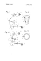
- FIG. 1 is a fragmentary side elevation schematically showing a spinning apparatus in accordance with this invention
- FIG. 2 is a side elevation in vertical section showing a twisting mechanism
- FIG. 3 is a plan view of the twisting mechanism
- FIG. 4 is a fragmentary side elevation partly in vertical section showing another embodiment of the twisting mechanism.
- the spinning apparatus for continuous operation of this invention shown in FIGS. 1 to 3 comprises a twisting mechanism disposed between draft rollers 5 and discharge rollers 6.
- the twisting mechanism includes a spindle l in the form of an inverted cone having an upwardly progressively increasing diameter.
- An upwardly flaring tubular rotary body 3 in the form of an inverted cone is disposed concentrically of the spindle 1 with ball bearings 2 interposed therebetween.
- a spun yam guide ring 4 which is mounted on a support extending from the spindle 1 beyond the periphery of the tubular rotary body 3.
- the spindle is driven at a higher circumferential speed than the tubular rotary body 3, the arrangement further being such that the rotational speeds of the spindle 1, rotary body 3 and cheese bobbin 7 can be adjusted respectively as desired.
- Combing rollers 8 are positioned before the draft rollers 5.
- a roving S from the roving process is passed between combing rollers 8, between draft rollers 5, through the guide ring 4 on the spindle l. and is then wound around the outer peripheral surface of the tubular rotary body 3 one or two turns.
- the roving is then passed between the discharge rollers 6, through unillustrated dyeing bath and dryer and is wound up on the cheese bobbin 7.
- the spindle ll, tubular rotary body 3 and cheese bobbin 7 are positively driven, the circumferencial speed of the spindle 1 being higher than that of the tubular rotary body 3.
- the roving S sent out from the roving process is untwisted by the combing rollers 8, then drafted by the draft rollers and thereafter twisted between the guide ring 4 and the draft rollers 5 by virtue of the high speed rotation of the spindle 1. It is assured that the spun yarn will then be passed onto the outer peripheral surface of the tubular rotary body 3 and guided downward smoothly by virtue of the inverted conical shape of the rotary body 3 while being passed therearound once or twice. The yarn is thereafter moved between the discharge rollers 6 and taken up on the cheese bobbin 7. This mode of operation ensures continuous operation throughout the whole processes starting with spinning and ending up with winding after the finishing process.
- FIG. 4 shows a modified embodiment of the spinning apparatus for continuous operation in accordance with this invention.
- This embodiment is the same as the foregoing embodiment with respect to construction, operation and advantage except that when the roving sent forward between combing rollers 18 and draft rollers 15 is taken up on a cheese bobbin 17 by way of discharge rollers 16, the material is passed through a passage 11' extending from the top face of a spindle 11 to the side face of the top portion thereof and then through a guide ring 14 mounted at the distal end of an arm 12 projecting from the top side face and that a tubular rotary body 13 is in the form of a straight cylinder.
- a spinning apparatus for continuous operation comprising a twisting mechanism disposed between draft rollers and discharge rollers and composed of a spindle provided outwardly thereof with guide ring for a spun yarn and a tubular rotary body surrounding the spindle concentrically therewith, the spindle being driven at a higher circumferential speed than the tubular rotary body whereby the twisted yarn is wound around the outer peripheral surface of the tubular rotary body and then passed toward the discharge rollers.
- tubular rotary body is in the form of an inverted cone.
- tubular rotary body is in the form of a straight cylinder.
Landscapes
- Engineering & Computer Science (AREA)
- Mechanical Engineering (AREA)
- Textile Engineering (AREA)
- Spinning Or Twisting Of Yarns (AREA)
Applications Claiming Priority (2)
| Application Number | Priority Date | Filing Date | Title |
|---|---|---|---|
| JP11715170 | 1970-12-23 | ||
| JP12965770 | 1970-12-30 |
Publications (1)
| Publication Number | Publication Date |
|---|---|
| US3735575A true US3735575A (en) | 1973-05-29 |
Family
ID=26455319
Family Applications (1)
| Application Number | Title | Priority Date | Filing Date |
|---|---|---|---|
| US00209156A Expired - Lifetime US3735575A (en) | 1970-12-23 | 1971-12-17 | Spinning apparatus for continuous operation |
Country Status (4)
| Country | Link |
|---|---|
| US (1) | US3735575A (OSRAM) |
| CH (1) | CH549101A (OSRAM) |
| DE (1) | DE2163558A1 (OSRAM) |
| FR (1) | FR2119065B1 (OSRAM) |
Cited By (7)
| Publication number | Priority date | Publication date | Assignee | Title |
|---|---|---|---|---|
| US4231219A (en) * | 1979-06-04 | 1980-11-04 | Akzona Incorporated | Method and apparatus for alleviating tight spots in false twist textured yarn |
| US4395873A (en) * | 1980-06-18 | 1983-08-02 | Filature Saint Andre | Process of and apparatus for spinning a bundle of textile fibres having no appreciable twist |
| US4562694A (en) * | 1983-07-07 | 1986-01-07 | Sumar Cesar P | Device for attachment to drawtwister machines to produce multifilament yarns with S or Z twist effect |
| US4726180A (en) * | 1986-05-07 | 1988-02-23 | Rieter Scragg | False twist apparatus |
| US4956970A (en) * | 1987-10-23 | 1990-09-18 | Barmag Ag | False twist roll |
| US20110061599A1 (en) * | 2008-02-11 | 2011-03-17 | Joseph Edward Boudreau | System and Apparatus for the Preservation and Transportation of Products Including Live Aquatic Species |
| US20170152124A1 (en) * | 2014-05-08 | 2017-06-01 | Maschinenfabrik Rieter Ag | Textile Machine for the Production of Roving and Method for Operating the Same |
Families Citing this family (1)
| Publication number | Priority date | Publication date | Assignee | Title |
|---|---|---|---|---|
| RU2237761C2 (ru) * | 2002-07-29 | 2004-10-10 | Овсянников Николай Дмитриевич | Способ импульсно-спирального кручения нитей (варианты) |
Citations (1)
| Publication number | Priority date | Publication date | Assignee | Title |
|---|---|---|---|---|
| US2091153A (en) * | 1936-07-07 | 1937-08-24 | H & B American Machine Company | Long draft apparatus and process for drawing textile rovings |
Family Cites Families (2)
| Publication number | Priority date | Publication date | Assignee | Title |
|---|---|---|---|---|
| FR1119281A (fr) * | 1955-01-11 | 1956-06-18 | Dispositifs de torsion simultanée à l'assemblage des fils | |
| FR1137374A (fr) * | 1955-06-22 | 1957-05-28 | Nouveau dispositif de torsion simultanée à l'assemblage des fils |
-
1971
- 1971-12-17 US US00209156A patent/US3735575A/en not_active Expired - Lifetime
- 1971-12-21 DE DE19712163558 patent/DE2163558A1/de active Pending
- 1971-12-22 CH CH1875171A patent/CH549101A/xx not_active IP Right Cessation
- 1971-12-23 FR FR7146442A patent/FR2119065B1/fr not_active Expired
Patent Citations (1)
| Publication number | Priority date | Publication date | Assignee | Title |
|---|---|---|---|---|
| US2091153A (en) * | 1936-07-07 | 1937-08-24 | H & B American Machine Company | Long draft apparatus and process for drawing textile rovings |
Cited By (9)
| Publication number | Priority date | Publication date | Assignee | Title |
|---|---|---|---|---|
| US4231219A (en) * | 1979-06-04 | 1980-11-04 | Akzona Incorporated | Method and apparatus for alleviating tight spots in false twist textured yarn |
| US4395873A (en) * | 1980-06-18 | 1983-08-02 | Filature Saint Andre | Process of and apparatus for spinning a bundle of textile fibres having no appreciable twist |
| US4562694A (en) * | 1983-07-07 | 1986-01-07 | Sumar Cesar P | Device for attachment to drawtwister machines to produce multifilament yarns with S or Z twist effect |
| US4726180A (en) * | 1986-05-07 | 1988-02-23 | Rieter Scragg | False twist apparatus |
| US4956970A (en) * | 1987-10-23 | 1990-09-18 | Barmag Ag | False twist roll |
| US20110061599A1 (en) * | 2008-02-11 | 2011-03-17 | Joseph Edward Boudreau | System and Apparatus for the Preservation and Transportation of Products Including Live Aquatic Species |
| US10463027B2 (en) * | 2008-02-11 | 2019-11-05 | 3225335 Nova Scotia Limited | System and apparatus for the preservation and transportation of products including live aquatic species |
| US20170152124A1 (en) * | 2014-05-08 | 2017-06-01 | Maschinenfabrik Rieter Ag | Textile Machine for the Production of Roving and Method for Operating the Same |
| US10533267B2 (en) * | 2014-05-08 | 2020-01-14 | Maschinenfabrik Rieter Ag | Textile machine for the production of roving and method for operating the same |
Also Published As
| Publication number | Publication date |
|---|---|
| CH549101A (de) | 1974-05-15 |
| FR2119065B1 (OSRAM) | 1975-02-07 |
| FR2119065A1 (OSRAM) | 1972-08-04 |
| DE2163558A1 (de) | 1972-08-10 |
Similar Documents
| Publication | Publication Date | Title |
|---|---|---|
| US3328949A (en) | Device for continuous centrifugal spinning | |
| US3445993A (en) | Method of and apparatus for producing core yarns | |
| US3735575A (en) | Spinning apparatus for continuous operation | |
| US3174270A (en) | Method and apparatus for winding thread | |
| KR100319670B1 (ko) | 기모사의 가공방법 및 그 장치 | |
| CN113195808B (zh) | 用于改造纺纱机的方法及由上述方法得到的改进的纺纱机 | |
| US4642981A (en) | Rotor with yarn guide for open-end spinning | |
| US2431323A (en) | Method of starting thread on bobbins | |
| CN206219741U (zh) | 捻线锭子 | |
| CN106567163B (zh) | 一种环锭包缠纱纺纱装置和纺纱方法 | |
| US3969882A (en) | Process and apparatus for fiber wetting in spinning device of the ring-spindle-traveler type | |
| US2291819A (en) | Method of spinning | |
| CN113215689A (zh) | 一种纺纱方法以及具有这种方法的纺纱设备 | |
| CN113215694A (zh) | 一种纱线加捻和卷绕分离的纺纱方法以及纺纱机 | |
| US3038293A (en) | Pavek | |
| US2249777A (en) | Method and apparatus for the twisting of thread | |
| US10900144B2 (en) | Roving-forming element for a roving machine as well as a roving machine equipped therewith | |
| US3468116A (en) | Method and apparatus for open end spinning | |
| US3336742A (en) | Yarn twist controlling device | |
| CN110541216B (zh) | 一种段彩股线细纱机、段彩股线、面料及其生产方法 | |
| US2318162A (en) | Process and apparatus for twisting rayon | |
| CN113201813A (zh) | 一种独立卷绕的纺纱方法以及纺纱机 | |
| EP0066623A4 (en) | IMPROVED DEVICE AND METHOD FOR SPINNING, TWISTING AND WINDING A YARN. | |
| US3557541A (en) | Double twist spindle and method of twisting | |
| US2591243A (en) | Process for the manufacture of rayon from viscose with high elongation and spooling in centrifugal cups |