US3731641A - Looper - Google Patents
Looper Download PDFInfo
- Publication number
- US3731641A US3731641A US00091106A US3731641DA US3731641A US 3731641 A US3731641 A US 3731641A US 00091106 A US00091106 A US 00091106A US 3731641D A US3731641D A US 3731641DA US 3731641 A US3731641 A US 3731641A
- Authority
- US
- United States
- Prior art keywords
- needle
- row
- machine according
- crown
- looping machine
- Prior art date
- Legal status (The legal status is an assumption and is not a legal conclusion. Google has not performed a legal analysis and makes no representation as to the accuracy of the status listed.)
- Expired - Lifetime
Links
- 238000009958 sewing Methods 0.000 claims abstract description 38
- 230000015572 biosynthetic process Effects 0.000 claims abstract description 8
- 238000004873 anchoring Methods 0.000 claims description 2
- 238000012546 transfer Methods 0.000 description 7
- 238000000034 method Methods 0.000 description 4
- 238000009940 knitting Methods 0.000 description 2
- 238000012986 modification Methods 0.000 description 2
- 230000004048 modification Effects 0.000 description 2
- 230000035515 penetration Effects 0.000 description 2
- 238000005266 casting Methods 0.000 description 1
- 238000013461 design Methods 0.000 description 1
- 230000000694 effects Effects 0.000 description 1
- 230000001788 irregular Effects 0.000 description 1
- 230000007246 mechanism Effects 0.000 description 1
- 230000000149 penetrating effect Effects 0.000 description 1
- 230000009467 reduction Effects 0.000 description 1
- 238000012549 training Methods 0.000 description 1
- 230000007704 transition Effects 0.000 description 1
Images


Classifications
-
- D—TEXTILES; PAPER
- D05—SEWING; EMBROIDERING; TUFTING
- D05B—SEWING
- D05B7/00—Linking machines, e.g. for joining knitted fabrics
Definitions
- the present invention relates to a looping machine with an advancing needle row bed formed by individual needles of this needle row, with grooves extending in the longitudinal direction and, more particularly, to a looping machine wherein the material to be looped and to be connected by a warp or chain stitch, by means of stitch-forming tools with a needle stitching from the inside toward the outside or vice versa, is transferred onto these row needles.
- a looper serves for bordering and/or combining looping material, such as hoisery or knitted goods or the like by a single or double-thread warp stitch.
- the stitch-forming tools must engage stitch by stitch the sections of material to be combined and sew the same together.
- This operation for example the bordering of a cut piece of material with a looping edge, can be conducted as described immediately hereinbelow.
- the looping edge which is produced in accordance with quite a specific scheme, i.e., according to a predetermined knitting sequence with a specific number of auxiliary stitches, is transferred stitch by stitch and row by row, for example manually, in the transfer or the long loop row. Thereafter, the blind transfer onto the row needles of the material to be attached is effected, and furthermore the turning down of the looping edge and another stitch-by-stitch and rowby-row transfer thereof.
- the further procedure in this operation and the techniques being employed in connection therewith need not be discussed in detail herein.
- connection of the looping material transferred onto the machine is effected by means of a single-or double-thread warp or chain stitch by means of a sewing needle guided successively on each needle of the needle row in a groove.
- This sewing needle can form the seam on the inside of the needle row crown as well as on the outside, i.e., the needle stitches either from the inside toward the outside or vice-versa.
- the looping seam is formed above the row needles. Since the borders or edges, in the above-described transfer technique customary nowadays, are transferred in such a manner that these borders are disposed above the row needles and the top rows are positioned underneath the row needles, the stitch loop held in each instance by the row needle remains perforce underneath the looping seam. After detaching the top rows, these stitch loops remain standing. This results in a slovenly and thus unattrac tive appearance of the looped goods, especially when the hem and the section of material deviate from each other with respect to color.
- care must be taken that the overhanging stitch loops are placed against the looping seam. This is effected by pulling the borders or the edge back by hand.
- the present invention is aimed at the problem of providing a looping machine wherein the abovedescribed disadvantages do not occur, so that additional operations on the looped material can be eliminated.
- a further feature of the machine is provided with a needle row crown and the present invention resides in that the entire drive for the sewing needle penetrating underneath each row needle, is disposed below the needle row crown. Accordingly, the entire drive for the sewing needle is advantageously protected within the top of the machine so that the needle crown passes over into a free area.
- the sewing needle can consist of a conventional spring beard needle, in accordance with a preferred embodiment of the invention.
- the stitch forming tools are driven by way of kinematic trains which are to be exactly controlled with respect to their inertial forces so that the looping machine can operate vibration-free at very high speeds.
- the advantages attainable with the present invention reside particularly in the avoidance of stitch loops extending beyond the looping seam, as they occur when the sewing needle penetrates above the row needle.
- the stitch loop is engaged at its lowermost curved portion so that the looping seam in each case represents the end of the edges or the hem sections.
- a strictly defined, clear transition is accomplished between the parts to be connected, so that cumbersome finishing operations by highly paid personnel are eliminated.
- the looped goods leave the needle crown of the looping machine in a flawless condition.
- FIG. 1 shows a looping product produced by means of a looping machine in accordance with the state of the art known heretofore;
- FIG. 2 shows a looping work produced with a looping machine according to the present invention
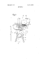
- FIG. 3 is a lateral view of a looping machine according to the present invention.
- FIG. 4 is an enlarged sectional view through the needle row crown in the plane of the encircled area B of FIG. 3;
- FIG. 5 is an enlarged view of a row needle in cooperation with a sewing needle.
- FIG. 1 a portion of a needle row crown is schemati' cally illustrated in a developed planar projection to show the arrangement in accordance with the state of the prior art.
- the row needles 41 carry a piece of material 42 which is to be sewn together, for example, with a facing 43.
- one side of the facing 43 is transferred stitch by stitch and row by row.
- the piece of material 42 is transferred to the needles without regard to stitches and rows, i.e., in a blind fashion, and after turning down the free side of the facing 43, the latter is likewise transferred in accordance with stitches and rows.
- the stitch loops 44 which project at the distance a,” loosely extend from the piece of material, so that an undeveloped or a slovenly total impression of the looped material results. This impression can become even more unattractive, especially due to differences in color.
- the looping trim 43 in order to obtain a clean or strictly defined termination of the looping trim 43, the latter must be pulled back in the upward direction toward the looping seam by hand, so that the stitch loops 4 contact this seam, as illustrated in FIG. 2.
- This illustrated condition can be attained either by an expensive finishing operation or by means of a looping machine according to the present invention, wherein a piece of material 2 and a facing 3 are connected in each case in the point of penetration 5 of the sewing needle.
- the row needles 1 shown in FIG. 2 correspond to a looper according to the present invention, as illustrated in the lateral view of FIG. 3.
- This looping machine consists essentially of a stationary bottom part or base 7 and a rotatable top machine part or superstructure 8.
- the stationary bottom part consists of, inter alia, a tubular framework 9 attached to a gear 10, underneath which the drive motor 1 1 is mounted by flange means.
- the speed of the main shaft 12 driving the looping machine can be varied, preferably infinitely, via the gear by means of a hand lever 13.
- the drive elements 16 are illustrated schematically to simplify the understanding of the present invention.
- the main drive shaft 12 carries a worm gear 17 meshing with a second worm gear 18.
- This worm gear transmits the rotary motion to an eccentric 19, which drives the needle bar 21 via an angle lever 20.
- the needle bar 21 is displaceably mounted in the needle bar holder 22, and the needle bar holder 22 is arranged to be pivotable about the axis of the main drive shaft 12.
- a lateral movement is impartedto the needle bar holder 22 so that the sewing needle 24 can follow the rotary motion of the needle row arranged in the form of a needle row crown 25 i.e., ring-shaped, during the stitch formation.
- the needle row crown 25 can be freely rotated after operating a locking button 26.
- the arm 15 receives the drive means 27 for the gripper or looper 28.
- the stitch forming means have drive means effected via train means.
- the sewing needle stitches either from the inside toward the outside or from the outside toward the inside for connecting the material to be looped by means of a warp stitch.
- the needle row crown 25 is shown in an enlarged view.
- the row needles 1 are fixedly anchored in a needle bed 29, preferably by incorporating them into the bed by casting, and are furthermore secured by means of a pressure plate 30.
- the needle crown body 31 carries the drive gear 32 in addition to the needle bed 29 and the pressure plate 30, and the drive gear 32 is in connection with drive means running synchronously with respect to the needle bar drive mechanism 16 (not shown).
- the needle bed 29 and the pressure plate 30 as well as the drive gear 32 are fixedly mounted in the needle crown body 31 by means of securing means 33, which can have any desired design.
- the mounting of the needle crown body 31 with respect to the partially illustrated ring 34 is effected by way of a roller or sliding bearing 35.
- the needle bar 21, the mounting 22 of which is partially illustrated, carries the sewing needle 24 at its free end in a clamping screw 36.
- the sewing needle 24 is guided in grooves 6, as shown in FIGS. 2 and 5, provided on the underside of the row needles 1, as seen in the direction A in correspondence with the downwardly hanging portion of the material.
- the looping seam is disposed correspondingly underneath each row needle 1 as can be seen, in particular, from FIG. 2.
- the drive for the needle bar and/or the drive for the gripper can be effected by cam control or by trains.
- Looping machine comprising an advancing needle row bed formed from individual row needles with grooves extending in the longitudinal direction thereof, and stitch forming means including a sewing needle for stitching either from the inside toward the outside or from the outside toward the inside for connecting the material to be looped by means of a warp stitch, wherein the material is transferred to the row needles, the sewing needle being operatively received in the grooves of the row needles, the grooves being provided on the underside of the row needles corresponding to the downwardly hanging material, whereby the sewing needle engages into the material for stitch formation.
- looping machine wherein the needle row bed is ring-shaped and forms a part of a needle row crown, and the stitch forming means includes drive means for the sewing needle, said drive means being located below the needle row crown.
- looping machine wherein the needle row bed is ring-shaped and forms a part of a needle row crown, and the stitch forming means includes drive means for the sewing needle, said drive means being located below the needle row crown.
- looping machine according to claim 1, wherein the stitch forming means have drive means effected via train means.
- looping machine wherein the needle row bed is ring-shaped and forms a part of a needle row crown, and the stitch forming means includes drive means for the sewing needle, said drive means being located below the needle row crown.
- Looping machine further comprising a needle bar and a needle bar holder, the sewing needle being operatively held in the needle bar which, in turn, is displaceably mounted in the needle bar holder pivotable about the axis of a main drive shaft for the looping machine.
- looping machine wherein the row needles are fixedly anchored in the needle bed, and pressure plate means is additionally provided for anchoring the row needles in the needle bed.
- looping machine according to claim 9, wherein the needle row crown includes a crown body carrying the needle bed and the pressure plate means.
Landscapes
- Engineering & Computer Science (AREA)
- Textile Engineering (AREA)
- Sewing Machines And Sewing (AREA)
Applications Claiming Priority (1)
| Application Number | Priority Date | Filing Date | Title |
|---|---|---|---|
| DE19691958049 DE1958049C3 (de) | 1969-11-19 | Kettelmaschine |
Publications (1)
| Publication Number | Publication Date |
|---|---|
| US3731641A true US3731641A (en) | 1973-05-08 |
Family
ID=5751492
Family Applications (1)
| Application Number | Title | Priority Date | Filing Date |
|---|---|---|---|
| US00091106A Expired - Lifetime US3731641A (en) | 1969-11-19 | 1970-11-19 | Looper |
Country Status (2)
| Country | Link |
|---|---|
| US (1) | US3731641A (OSRAM) |
| FR (1) | FR2069703A5 (OSRAM) |
Cited By (1)
| Publication number | Priority date | Publication date | Assignee | Title |
|---|---|---|---|---|
| WO2025208111A1 (en) | 2024-03-29 | 2025-10-02 | Biomea Fusion, Inc. | Heterocyclic glp-1r agonists |
Citations (4)
| Publication number | Priority date | Publication date | Assignee | Title |
|---|---|---|---|---|
| US166805A (en) * | 1875-08-17 | Improvement in machines for sewing hosiery-seams | ||
| GB845970A (en) * | 1957-04-10 | 1960-08-24 | Exacta Officina Meccanica Spec | Improvements to linking machines of a circular type |
| US3083655A (en) * | 1959-09-10 | 1963-04-02 | Frederick W Beck | Linking machines |
| US3352264A (en) * | 1962-02-10 | 1967-11-14 | Matthews & Birkhamshaw Ltd | Fabric linking machines |
-
1970
- 1970-11-19 FR FR7041598A patent/FR2069703A5/fr not_active Expired
- 1970-11-19 US US00091106A patent/US3731641A/en not_active Expired - Lifetime
Patent Citations (4)
| Publication number | Priority date | Publication date | Assignee | Title |
|---|---|---|---|---|
| US166805A (en) * | 1875-08-17 | Improvement in machines for sewing hosiery-seams | ||
| GB845970A (en) * | 1957-04-10 | 1960-08-24 | Exacta Officina Meccanica Spec | Improvements to linking machines of a circular type |
| US3083655A (en) * | 1959-09-10 | 1963-04-02 | Frederick W Beck | Linking machines |
| US3352264A (en) * | 1962-02-10 | 1967-11-14 | Matthews & Birkhamshaw Ltd | Fabric linking machines |
Cited By (1)
| Publication number | Priority date | Publication date | Assignee | Title |
|---|---|---|---|---|
| WO2025208111A1 (en) | 2024-03-29 | 2025-10-02 | Biomea Fusion, Inc. | Heterocyclic glp-1r agonists |
Also Published As
| Publication number | Publication date |
|---|---|
| DE1958049A1 (de) | 1971-05-19 |
| DE1958049B2 (de) | 1977-05-12 |
| FR2069703A5 (OSRAM) | 1971-09-03 |
Similar Documents
| Publication | Publication Date | Title |
|---|---|---|
| US2966130A (en) | Sewing machine and loop-taker mechanisms therefor | |
| JPH07112517B2 (ja) | オ−バロツク縫いミシン | |
| US3602168A (en) | Chain stitch forming device for a lock stitch sewing machine | |
| CN101187115A (zh) | 刺绣缝纫机 | |
| US4122787A (en) | Sewing method and machine | |
| US4134350A (en) | Combined button stitching and sewing machine | |
| US3731641A (en) | Looper | |
| US3033139A (en) | Stitch forming mechanism of lock-stitch sewing machine for zigzag sewing | |
| JPH08246323A (ja) | 刺繍素材の縫い付け方法 | |
| US3125049A (en) | Sewing machine | |
| US3384042A (en) | Sewing machine | |
| JPS6060895A (ja) | ボビンに下糸を巻取る方法 | |
| US3675603A (en) | Sewing machine convertible from lock stitch to chain stitch | |
| US1283437A (en) | Lock-stitch sewing-machine. | |
| US3447497A (en) | Device for basting in lock-stitch sewing machines | |
| US4502398A (en) | Throat plate for a double lockstitch automatic sewing arrangement | |
| US1433241A (en) | Sewing machine | |
| US2063995A (en) | Ornamented loop-stitch sewing machine | |
| US3756176A (en) | Sewing machine slotted thread take-up lever | |
| KR890003392Y1 (ko) | 자수기의 특수사 자수봉침장치 | |
| US2599418A (en) | Stitch-forming method and apparatus | |
| US591384A (en) | Overedge sewing-machine | |
| US1329245A (en) | Sewing-machine | |
| US2244224A (en) | Blind stitch sewing machine | |
| US836849A (en) | Take-up mechanism for sewing-machines. |