US3727645A - Wilton carpet looms - Google Patents
Wilton carpet looms Download PDFInfo
- Publication number
- US3727645A US3727645A US00155039A US3727645DA US3727645A US 3727645 A US3727645 A US 3727645A US 00155039 A US00155039 A US 00155039A US 3727645D A US3727645D A US 3727645DA US 3727645 A US3727645 A US 3727645A
- Authority
- US
- United States
- Prior art keywords
- sley
- guide
- loom
- fingers
- wire
- Prior art date
- Legal status (The legal status is an assumption and is not a legal conclusion. Google has not performed a legal analysis and makes no representation as to the accuracy of the status listed.)
- Expired - Lifetime
Links
- 238000003780 insertion Methods 0.000 claims abstract description 18
- 230000037431 insertion Effects 0.000 claims abstract description 18
- 238000010009 beating Methods 0.000 claims description 2
- 238000000034 method Methods 0.000 claims description 2
- 238000009941 weaving Methods 0.000 claims description 2
- 238000010276 construction Methods 0.000 description 4
Images


Classifications
-
- D—TEXTILES; PAPER
- D03—WEAVING
- D03D—WOVEN FABRICS; METHODS OF WEAVING; LOOMS
- D03D39/00—Pile-fabric looms
Definitions
- the guide is preferably constituted by spaced fingers each formed with a guide slot and extending downwardly from a cross-member mounted to rotate so as to swing the fingers into and out of their operative position in relation to the sley.
- a movable guide is provided so as to cooperate with the sley to define a passage across the width of the loom for the insertion of each successive wire together with mechanism for moving the guide out of the path of the inserted wire during the beat-up movement of the sley and for returning it to its operative position in relation to the sley prior to the insertion of the next wire.
- the combination of the guide and the sley provides an enclosed path for the wire or separate enclosed paths for the two halves of a split wire, thus maintaining complete control over the wire and permitting insertion of successive wires at any speed required, even for the widest looms.
- the guide e is constituted by spaced fingers each formed with a slot and extending downwardly from a crossmember mounted to rotate so as to swing the fingers into and out of their operative position.
- the open face of each slot bears against the face of the sley so as to define the enclosed passage previously referred to.
- the fact that the slots have open faces enables the fingers to be swung upwardly out of the path of the sley to enable beat-up to proceed.
- Such a construction of guide has relatively little inertia and thus permits very high speeds of operation.
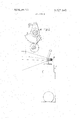
- FIG. 1 is a diagrammatic side elevation showing the mechanism inposition for the insertion ofa wire
- FIG. 2 is a view similar to FIG. 1 but showing the position of the parts of the mechanism at the conclu sion of beat-up;
- FIG. 3 is a sectional end view of the upper portion of FIG. I seen from the right hand side.
- the loom to which the mechanism is fitted is of standard con struction and is therefore neither illustrated nor described.
- the only part of the normal construction of the loom shown in the drawings is the sley which is indicated generally as 1 in FIGS. I and 2.
- the .guide mechanism is intended for the guiding of split wires, one of which is seen in FIG. 3 and comprises two spaced wires 2 extending from a common member 3 at one end.
- the individual wires are extremely flexible and, particularly with very wide looms, are difficult to control during insertion.
- Guide mechanism for this purpose comprises number of fingers 5 spaced at regular intervals along a shaft 6, as best seen in FIG. 3. As best seen in FIGS. 1 and 2, each finger is formed with a pair of open sided guide slots 7 for the reception of the two wires 2. In the operative position shown in FIG. I, each finger 5 bears against the face of the sley 1 to form a enclosed passage into which the wire can be inserted.
- the warp yarns are shown diagrammatically 'in FIGS.. 1 and 2, the pile warps being indicated as 8 and 9.
- the healds controlling the shed are indicated diagrammatically as 10. It will be seen that each individual wire 2 is inserted beneath one of the pile warps 8 and 9.
- the wires can be inserted very rapidly and as soon as the insertion is complete, the fingers 5 are lifted from the position shown in FIG. 1 to that shown in FIG. 2.
- the shaft 6 is caused to rotate by the engagement between a toothed wheel 14 mounted on the shaft which meshes with a toothed sector 15 mounted on a rocker shaft 16 and controlled by a rod 17. Movement of the rod 17 to the right from the position of FIG. 1 to the position of FIG. 2 causes the shaft 6 to rotate in an anticlockwise direction to swing the fingers 5 upwardly shown in FIG. 2, carrying the split wires 2 with it so that they are beaten up into a body of the carpet shown as 18.
- the sley 1 returns to the position of FIG. 1 and reverse movement of the rod 17 swings the fingers 5 downwardly back from the position of FIG. 2 to the position of FIG. 1 in which they again bear against the face of the sley in readiness for the insertion of the next wire.
- FIG. 3 This indicates the close spacing of the fingers 5 which in a typical example are 5 inches long, three-sixteenths inch wide and spaced at approximately inch pitch across the width of the loom.
- the wire is thus supported at very frequent intervals across the full width of the loom and is thus maintained fully under control during insertion.
- the shaft 6 is mounted to turn in a bearing 20 mounted in a bracket 21 and the shaft 16 turns in a similar bearing 22.
- the sector 15 is keyed to the shaft 16 so as to turn with it and thus to transmit drive to the wheel 14 and thus to the shaft 6.
- the rod 17 is driven from the normal driving mechanism of the loom so that the parts just described are driven in synchronism with the normal steps of operation.
- a Wilton carpet loom having a sley for beating up weft yarns in a weaving process and mechanism for inserting pile wires across the width of the loom
- the improvement which comprises a movable guide cooperating with said sley to define a passage across the width of said loom for the insertion of successive pile-defining wires, said guide comprising a shaft and a positions in relation to said sley prior to the insertion of a further wire.
- a loom improvement as claimed in claim 1 in which said guide is formed with two guide slots positioned to cooperate with said sley to define two passages, one for receiving each half ofa split pile wire.
Landscapes
- Engineering & Computer Science (AREA)
- Textile Engineering (AREA)
- Looms (AREA)
Applications Claiming Priority (1)
| Application Number | Priority Date | Filing Date | Title |
|---|---|---|---|
| GB3093770 | 1970-06-25 |
Publications (1)
| Publication Number | Publication Date |
|---|---|
| US3727645A true US3727645A (en) | 1973-04-17 |
Family
ID=10315441
Family Applications (1)
| Application Number | Title | Priority Date | Filing Date |
|---|---|---|---|
| US00155039A Expired - Lifetime US3727645A (en) | 1970-06-25 | 1971-06-21 | Wilton carpet looms |
Country Status (4)
| Country | Link |
|---|---|
| US (1) | US3727645A (en:Method) |
| BE (1) | BE768973A (en:Method) |
| FR (1) | FR2096494B1 (en:Method) |
| GB (1) | GB1331495A (en:Method) |
Cited By (1)
| Publication number | Priority date | Publication date | Assignee | Title |
|---|---|---|---|---|
| US20120190257A1 (en) * | 2009-05-13 | 2012-07-26 | Schonherr Textilmaschinenbau Gmbh | Method for simultaneously weaving two fabrics, fabric adapted to be woven with such a method and loom usable with such a method |
Citations (3)
| Publication number | Priority date | Publication date | Assignee | Title |
|---|---|---|---|---|
| US7660A (en) * | 1850-09-24 | Loom foe weaving tapestry and brussels carpet | ||
| US1706371A (en) * | 1927-02-24 | 1929-03-19 | F A Whitney Carriage Company | Loom |
| DE532512C (de) * | 1929-10-31 | 1931-09-02 | Ernst Kurtz | Vorrichtung zum Festhalten der Zugruten fuer Rutenwebstuehle |
Family Cites Families (2)
| Publication number | Priority date | Publication date | Assignee | Title |
|---|---|---|---|---|
| DE566912C (de) * | 1931-10-30 | 1932-12-23 | Hans Eilhauer | Drahtwebstuhl |
| FR981374A (fr) * | 1948-12-30 | 1951-05-25 | Métier à tisser |
-
1970
- 1970-06-25 GB GB3093770A patent/GB1331495A/en not_active Expired
-
1971
- 1971-06-21 US US00155039A patent/US3727645A/en not_active Expired - Lifetime
- 1971-06-24 BE BE768973A patent/BE768973A/xx not_active IP Right Cessation
- 1971-06-25 FR FR7123346A patent/FR2096494B1/fr not_active Expired
Patent Citations (3)
| Publication number | Priority date | Publication date | Assignee | Title |
|---|---|---|---|---|
| US7660A (en) * | 1850-09-24 | Loom foe weaving tapestry and brussels carpet | ||
| US1706371A (en) * | 1927-02-24 | 1929-03-19 | F A Whitney Carriage Company | Loom |
| DE532512C (de) * | 1929-10-31 | 1931-09-02 | Ernst Kurtz | Vorrichtung zum Festhalten der Zugruten fuer Rutenwebstuehle |
Cited By (4)
| Publication number | Priority date | Publication date | Assignee | Title |
|---|---|---|---|---|
| US20120190257A1 (en) * | 2009-05-13 | 2012-07-26 | Schonherr Textilmaschinenbau Gmbh | Method for simultaneously weaving two fabrics, fabric adapted to be woven with such a method and loom usable with such a method |
| US8651150B2 (en) * | 2009-05-13 | 2014-02-18 | Schonherr Textilmaschinenbau BMBH | Method for simultaneously weaving two fabrics, fabric adapted to be woven with such a method and loom usable with such a method |
| US20140144542A1 (en) * | 2009-05-13 | 2014-05-29 | Schonherr Textilmaschinenbau Gmbh | Fabrics simultaneously woven from two distance fabrics |
| US9410272B2 (en) * | 2009-05-13 | 2016-08-09 | Schonherr Textilmaschinenbau Gmbh | Fabrics simultaneously woven from two distance fabrics |
Also Published As
| Publication number | Publication date |
|---|---|
| FR2096494B1 (en:Method) | 1974-03-22 |
| GB1331495A (en) | 1973-09-26 |
| BE768973A (fr) | 1971-12-24 |
| FR2096494A1 (en:Method) | 1972-02-18 |
Similar Documents
| Publication | Publication Date | Title |
|---|---|---|
| US3799209A (en) | Machine for forming triaxial fabrics | |
| US3428095A (en) | Cloth motion in looms | |
| US2095576A (en) | Weft inserting and beating-up mechanism of looms for weaving | |
| US3499471A (en) | Method of weaving velvet tapes and the like | |
| US3590880A (en) | Apparatus and method for operating a loom | |
| US3727645A (en) | Wilton carpet looms | |
| US3640314A (en) | Shed-forming apparatus on a loom | |
| US3910317A (en) | Weaving machine for terry cloth | |
| US3682205A (en) | Needle loom | |
| US3111966A (en) | Method and apparatus for simultaneously weaving lengths of fabric | |
| US3720236A (en) | Arrangement for forming a selvage for use on a loom | |
| US955211A (en) | Power-loom for weaving textile fabrics. | |
| US1739205A (en) | Loom for weaving terry fabrics of different heights | |
| US3379223A (en) | Beat-up mechanism for travelling-wave shedding looms | |
| US4057083A (en) | Double-layer weaving loom | |
| US4351367A (en) | Beat-up system | |
| US3320980A (en) | Weft laying mechanism for needle looms | |
| US3425459A (en) | Camming beat-up mechanism for looms | |
| US3968817A (en) | Method of and apparatus for continuous progressive beating up of weft in travelling-wave shedding looms | |
| US2902057A (en) | Weft needle operating mechanism for loom | |
| US3392756A (en) | Weft inserting apparatus in multiple looms | |
| US2337431A (en) | Beat-up mechanism for looms | |
| US3779286A (en) | Method and apparatus for weaving terry cloth | |
| US3409051A (en) | Pile fabric loom | |
| US1825110A (en) | Pile fabric loom |