US3720470A - Apparatus and method for optical determination of particle characteristics - Google Patents
Apparatus and method for optical determination of particle characteristics Download PDFInfo
- Publication number
- US3720470A US3720470A US00171915A US3720470DA US3720470A US 3720470 A US3720470 A US 3720470A US 00171915 A US00171915 A US 00171915A US 3720470D A US3720470D A US 3720470DA US 3720470 A US3720470 A US 3720470A
- Authority
- US
- United States
- Prior art keywords
- chamber
- particle
- suspension
- depth
- particles
- Prior art date
- Legal status (The legal status is an assumption and is not a legal conclusion. Google has not performed a legal analysis and makes no representation as to the accuracy of the status listed.)
- Expired - Lifetime
Links
Images

Classifications
-
- G—PHYSICS
- G01—MEASURING; TESTING
- G01N—INVESTIGATING OR ANALYSING MATERIALS BY DETERMINING THEIR CHEMICAL OR PHYSICAL PROPERTIES
- G01N15/00—Investigating characteristics of particles; Investigating permeability, pore-volume or surface-area of porous materials
- G01N15/10—Investigating individual particles
- G01N15/14—Optical investigation techniques, e.g. flow cytometry
- G01N15/1404—Handling flow, e.g. hydrodynamic focusing
-
- G—PHYSICS
- G01—MEASURING; TESTING
- G01N—INVESTIGATING OR ANALYSING MATERIALS BY DETERMINING THEIR CHEMICAL OR PHYSICAL PROPERTIES
- G01N15/00—Investigating characteristics of particles; Investigating permeability, pore-volume or surface-area of porous materials
- G01N15/10—Investigating individual particles
- G01N15/14—Optical investigation techniques, e.g. flow cytometry
- G01N15/1429—Signal processing
- G01N15/1433—Signal processing using image recognition
-
- G—PHYSICS
- G01—MEASURING; TESTING
- G01N—INVESTIGATING OR ANALYSING MATERIALS BY DETERMINING THEIR CHEMICAL OR PHYSICAL PROPERTIES
- G01N15/00—Investigating characteristics of particles; Investigating permeability, pore-volume or surface-area of porous materials
- G01N15/10—Investigating individual particles
- G01N15/14—Optical investigation techniques, e.g. flow cytometry
- G01N15/1404—Handling flow, e.g. hydrodynamic focusing
- G01N2015/1413—Hydrodynamic focussing
Definitions
- ABSTRACT A shallow chamber is provided for passing through it a stream which envelopes a capillary stream of the particles, the characteristics of which are to be determined.
- the particles are in suspension in this capillary stream, which moves over the lower wall of the shallow chamber.
- At least one wall of the flow-through chamber is transparent and is arranged so that the focal area of the observing microscope coincides with the depth of the capillary stream.
- ATTORNEYS APPARATUS AND METHOD FOR OPTICAL DETERMINATION OF PARTICLE CHARACTERISTICS BACKGROUND AND NATURE OF THE INVENTION utilizes an aperture member of small clear diameter which the particles, moving in suspension, pass one after the other. In order to pass the particles through the center of the aperture, for exact measurement of the particle volume, there is used an enveloping stream, and injection of the particles into the center of the opening. This system allows observation of particles by electrical signal.
- the aperture is illuminated and a photoelectric detector measures the intensity of the light behind the aperture.
- This system does not allow exact measurement of particle size as the optical signals also depend on the location of particles in the aperture and on their various paths. The latter problem is also encountered when particles are observed by optical response to their light scattering or fluorescence.
- the latter methods are complex, expensive and nevertheless of limited precision for a number of reasons, including the fact that they require lateral deflection of the particle suspension in front of the microscope objective, which causes unsymmetrical particle paths with respect to directions of illumination and observation. All these systems also tend to cause cloggingof the narrow aperture by relatively large particles carried in the suspension.
- the invention overcomes the problem which has been outlined. It allows precise optical measurement of particle characteristics in a stream. It also allows successive measurement of different particles. It avoids the failure of optical observation of some or many particles, caused by the aforementioned problems.
- the invention uses a shallow observation chamber wherein a particle stream of capillary depth is moved along one wall of the chamber by an enveloping stream which holds the particle stream at fixed distance from the microscope objective with a minimum of transverse motion and disturbance.
- focal depth of the objective substantially coincides with the capillary depth of the particle streams. Clogging of a capillary tube is safely avoided.
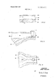
- FlG. l is schematic cross-sectional view of a first embodiment of this invention.
- FIGS. 2 and 3 are generally similar but partial views of second and third embodiments of the invention.
- FIG. 4 is a plan view of a fourth embodiment.
- FIG. 5 is a view generally similar to FIG. 1 but showing the use of a different optical system.
- FIG. 1 shows a system accordingto the invention wherein the shallow chamber is formed by transparent bottom wall 1 and transparent top wall 2, both advantageously consisting of plane and smoothly ground glass with surfaces normal to the axis of the observing microscope 3, the objective of which closely overlies the top wall, and the focal distance of which approximately coincides with the depth of the chamber above bottom 1.
- the width of the chamber can be same as or larger than the depth thereof.
- Envelope stream 4 has particle stream 5, which it surrounds and moves in the direction of the arrow.
- the depth of particle stream 5 is of capillary dimensions and substantially coincides with the depth of sharp focal definition of microscope 3, which depth is approximately defined by shaded area 6.
- Light source 7 and condensing lens 8 illuminate the particle stream.
- the arrangement allows precise optical observation of particle characteristics, as the suspension of particles passes the measuring area exclusively within the reach or depth of focus of the observing microscope.
- the arrangement contrasts with earlier systems in that it allows exact measurement of light absorption by particles with the aid of suitable means (not shown) for measurement of intensity of the light which passes the particle stream.
- the microscope system can be shifted freely in the direction of the stream, without impairment of precision of measurement, as constant measuring conditions can be maintained with respect to such factors as the distance between the particle suspension and the microscope objective, illumination of the suspension, velocity of particles and width of the stream. Adjustments are not nearly as critical as they were in former systems.
- the observing chamber 1, 2 desirably has a depth equal only to fractions of a millimeter and the depth of particle stream 5 in turn is only a fraction of the total depth.
- the Reynolds number for typical liquids used in this system preferably aqueous solutions is about 500 when the flow velocity is 5 meters per second and the chamber has a depth of 0.1 millimeter. This value of 500 is safely below the critical value of 2300.
- bottom wall 21 has a side inlet 27 through which a stream of particle suspension 25 enters the stream 24 of enveloping liquid.
- Walls 21, 22 of this system can be integral with walls 1 and 2 of FIG. 1, respectively, although this is not absolutely necessary.
- the form of aperture 27 and its diameter in the direction of enveloping stream 24 are not critical, so that the attachment can be produced simply and inexpensively. In a direction across the stream, the diameter of aperture 27 should equal the diameter of the following, illuminated observation area below the microscope objective.
- the particle suspension 25 then is limited both laterally and at the top by particle free liquid 24.
- this modified cross-section diagram schematically shows a system using relatively large apertures for introduction of the particle suspension, with continuous reduction of channel area between this aperture and the measuring region. This arrangement further reduces the danger of clogging.
- element 31 represents a relatively large side channel for suspension joining an even larger channel 33 for enveloping liquid, both leading to the small and shallow chamber for particle stream 35 to be observed.
- the system of FIG. 3 or any other suitable feed system may have the form, in plan view, which is shown in FIG. 4.
- the aperture of the feed channel for the particle suspension can be made wide enough to produce, pursuant to continuous reduction in which, a particle stream 45 of desired width, slightly narrower than observation area 6.
- FIG. 5 shows a modification of the optical system and corresponding possible modification of the observation chamber, according to the coincident top lighting method.
- bottom wall 51 can be opaque.
- Illuminating system 57, 58 illuminates particle stream 55, with focal depth 56, by means of a half mirrored plate 59 inserted between ocular and ob ective of the observing microscope 53.
- An apparatus for the optical determination of characteristics of particles in a suspension comprising:
- a shallow chamber having at least one planar wall
- laminar liquid flow means for entraining the suspension as a particle flow of capillary depth and for moving the particle flow along and in contact with the planar wall;
- said microscope means having a focal depth approximately coincident with said capillary depth.
- Apparatus according to claim 1 additionally including means for illuminating said particle flow in the region of focal depth.
- Apparatus according to claim 4 wherein the illuminating means is disposed opposite the microscope means, with said chamber between them.
- Apparatus according to claim 4 wherein the illuminating means is disposed on the same side of said chamber as the microscope means, with semi-reflective means for coincident illumination.
- a method of optical determination of characteristics of particles in a suspension comprising the steps of:
Landscapes
- Chemical & Material Sciences (AREA)
- Dispersion Chemistry (AREA)
- Physics & Mathematics (AREA)
- Health & Medical Sciences (AREA)
- Life Sciences & Earth Sciences (AREA)
- Analytical Chemistry (AREA)
- Biochemistry (AREA)
- General Health & Medical Sciences (AREA)
- General Physics & Mathematics (AREA)
- Immunology (AREA)
- Pathology (AREA)
- Optical Measuring Cells (AREA)
- Investigating Or Analysing Biological Materials (AREA)
- Investigating Or Analysing Materials By Optical Means (AREA)
Applications Claiming Priority (1)
| Application Number | Priority Date | Filing Date | Title |
|---|---|---|---|
| DE2050672A DE2050672C3 (de) | 1970-10-15 | 1970-10-15 | Durchflußküvette zur mikroskopfotometrischen Messung von in einer Flüssigkeit suspendierten Teilchen |
Publications (1)
| Publication Number | Publication Date |
|---|---|
| US3720470A true US3720470A (en) | 1973-03-13 |
Family
ID=5785230
Family Applications (1)
| Application Number | Title | Priority Date | Filing Date |
|---|---|---|---|
| US00171915A Expired - Lifetime US3720470A (en) | 1970-10-15 | 1971-08-16 | Apparatus and method for optical determination of particle characteristics |
Country Status (8)
| Country | Link |
|---|---|
| US (1) | US3720470A (enExample) |
| CA (1) | CA952733A (enExample) |
| CH (1) | CH523501A (enExample) |
| DE (1) | DE2050672C3 (enExample) |
| FR (1) | FR2094997A5 (enExample) |
| GB (1) | GB1281851A (enExample) |
| NL (1) | NL7101358A (enExample) |
| SE (1) | SE384273B (enExample) |
Cited By (12)
| Publication number | Priority date | Publication date | Assignee | Title |
|---|---|---|---|---|
| US3893766A (en) * | 1973-06-14 | 1975-07-08 | Coulter Electronics | Apparatus for orienting generally flat particles for slit-scan photometry |
| US3975084A (en) * | 1973-09-27 | 1976-08-17 | Block Engineering, Inc. | Particle detecting system |
| USRE29141E (en) * | 1973-06-14 | 1977-02-22 | Coulter Electronics, Inc. | Apparatus for orienting generally flat particles for sensing |
| US4056324A (en) * | 1975-05-10 | 1977-11-01 | Hildegard Gohde | Apparatus for counting and/or measuring particles suspended in a fluid medium |
| US4095775A (en) * | 1975-12-22 | 1978-06-20 | Hotham Geoffrey A | Particle evaluator |
| US4348107A (en) * | 1980-07-18 | 1982-09-07 | Coulter Electronics, Inc. | Orifice inside optical element |
| US4527114A (en) * | 1982-02-25 | 1985-07-02 | Coulter Electronics, Inc. | Electrical slit scanning apparatus |
| US4565448A (en) * | 1983-03-11 | 1986-01-21 | E. I. Du Pont De Nemours And Company | Particle counting apparatus |
| FR2573870A1 (fr) * | 1984-11-29 | 1986-05-30 | Int Remote Imaging Systems Inc | Procede d'utilisation d'un instrument du type microscope |
| US4647543A (en) * | 1983-02-25 | 1987-03-03 | Stoecker Winfried | Process for analyses to be carried out on immobilized biological tissue |
| US4660971A (en) * | 1984-05-03 | 1987-04-28 | Becton, Dickinson And Company | Optical features of flow cytometry apparatus |
| WO2001073403A1 (en) * | 2000-03-29 | 2001-10-04 | Corning Incorporated | Measuring inclusion depth |
Families Citing this family (1)
| Publication number | Priority date | Publication date | Assignee | Title |
|---|---|---|---|---|
| DE102007012866A1 (de) * | 2007-03-09 | 2008-09-18 | Fraunhofer-Gesellschaft zur Förderung der angewandten Forschung e.V. | Flusskanalsystem und Verfahren zum Anbinden von Analyten an Liganden |
Citations (2)
| Publication number | Priority date | Publication date | Assignee | Title |
|---|---|---|---|---|
| US2731877A (en) * | 1956-01-24 | clamann | ||
| US2732753A (en) * | 1956-01-31 | o konski |
-
1970
- 1970-10-15 DE DE2050672A patent/DE2050672C3/de not_active Expired
-
1971
- 1971-02-02 NL NL7101358A patent/NL7101358A/xx not_active Application Discontinuation
- 1971-02-12 SE SE7101813A patent/SE384273B/xx unknown
- 1971-05-12 FR FR7117080A patent/FR2094997A5/fr not_active Expired
- 1971-05-25 GB GB06789/71A patent/GB1281851A/en not_active Expired
- 1971-05-26 CA CA113,871A patent/CA952733A/en not_active Expired
- 1971-08-16 US US00171915A patent/US3720470A/en not_active Expired - Lifetime
- 1971-10-08 CH CH1468271A patent/CH523501A/de not_active IP Right Cessation
Patent Citations (2)
| Publication number | Priority date | Publication date | Assignee | Title |
|---|---|---|---|---|
| US2731877A (en) * | 1956-01-24 | clamann | ||
| US2732753A (en) * | 1956-01-31 | o konski |
Cited By (12)
| Publication number | Priority date | Publication date | Assignee | Title |
|---|---|---|---|---|
| US3893766A (en) * | 1973-06-14 | 1975-07-08 | Coulter Electronics | Apparatus for orienting generally flat particles for slit-scan photometry |
| USRE29141E (en) * | 1973-06-14 | 1977-02-22 | Coulter Electronics, Inc. | Apparatus for orienting generally flat particles for sensing |
| US3975084A (en) * | 1973-09-27 | 1976-08-17 | Block Engineering, Inc. | Particle detecting system |
| US4056324A (en) * | 1975-05-10 | 1977-11-01 | Hildegard Gohde | Apparatus for counting and/or measuring particles suspended in a fluid medium |
| US4095775A (en) * | 1975-12-22 | 1978-06-20 | Hotham Geoffrey A | Particle evaluator |
| US4348107A (en) * | 1980-07-18 | 1982-09-07 | Coulter Electronics, Inc. | Orifice inside optical element |
| US4527114A (en) * | 1982-02-25 | 1985-07-02 | Coulter Electronics, Inc. | Electrical slit scanning apparatus |
| US4647543A (en) * | 1983-02-25 | 1987-03-03 | Stoecker Winfried | Process for analyses to be carried out on immobilized biological tissue |
| US4565448A (en) * | 1983-03-11 | 1986-01-21 | E. I. Du Pont De Nemours And Company | Particle counting apparatus |
| US4660971A (en) * | 1984-05-03 | 1987-04-28 | Becton, Dickinson And Company | Optical features of flow cytometry apparatus |
| FR2573870A1 (fr) * | 1984-11-29 | 1986-05-30 | Int Remote Imaging Systems Inc | Procede d'utilisation d'un instrument du type microscope |
| WO2001073403A1 (en) * | 2000-03-29 | 2001-10-04 | Corning Incorporated | Measuring inclusion depth |
Also Published As
| Publication number | Publication date |
|---|---|
| SE384273B (sv) | 1976-04-26 |
| FR2094997A5 (enExample) | 1972-02-04 |
| DE2050672A1 (de) | 1972-04-20 |
| NL7101358A (enExample) | 1972-04-18 |
| DE2050672B2 (de) | 1974-06-12 |
| CA952733A (en) | 1974-08-13 |
| CH523501A (de) | 1972-05-31 |
| DE2050672C3 (de) | 1975-02-06 |
| GB1281851A (en) | 1972-07-19 |
Similar Documents
| Publication | Publication Date | Title |
|---|---|---|
| US20250369865A1 (en) | Disposable chip-type flow cell and flow cytometer using the same | |
| US20230417649A1 (en) | Apparatuses, Systems And Methods For Imaging Flow Cytometry | |
| US3720470A (en) | Apparatus and method for optical determination of particle characteristics | |
| US3984307A (en) | Combined particle sorter and segregation indicator | |
| US5552885A (en) | Measuring chamber for flow cytometer | |
| FI82772B (fi) | Floedescytometrisk apparat. | |
| US3873204A (en) | Optical extinction photoanalysis apparatus for small particles | |
| FI70481C (fi) | Foerfarande foer bestaemning av cellvolymen | |
| ES2360906T3 (es) | Detección óptica y análisis de partículas. | |
| US3761187A (en) | Flow-through chamber for photometers to measure and count particles in a dispersion medium | |
| US3827555A (en) | Particle sorter with segregation indicator | |
| US4915501A (en) | Device for measuring the light scattering of biological cells in flow cytophotometers | |
| US4710021A (en) | Particulate matter analyzing apparatus and method | |
| RU2006108798A (ru) | Оптический расходомер для измерения расхода газов и жидкостей в трубопроводах | |
| US20110254533A1 (en) | Coaxial Illumination Of Coulter Aperture In Full Function Hematology Analyzer | |
| JPH03170843A (ja) | 白血球の計測装置 | |
| DE69319184D1 (de) | Flüssigkeitsverschmutzungfühler | |
| GB2059051A (en) | An apparatus for measuring the aggregation of dispersed particles | |
| JPS63201554A (ja) | 粒子解析装置 | |
| RU2079131C1 (ru) | Устройство для анализа биологических объектов | |
| CN102308197B (zh) | 一次性芯片型流动室及使用该流动室的流式细胞仪 | |
| JPH0232235A (ja) | シースフロー式蛍光検出器 | |
| JPS63300940A (ja) | 粒子解析装置 | |
| GB2025606A (en) | Device for granulometric analysis of particles in fluids | |
| JPS6151542A (ja) | 粒子解析用光学系 |
Legal Events
| Date | Code | Title | Description |
|---|---|---|---|
| AS | Assignment |
Owner name: ORTHO DIAGNOSTICS, U.S. ROUTE 202, RARITAN, NJ. 08 Free format text: ASSIGNMENT OF ASSIGNORS INTEREST.;ASSIGNOR:PHYWE A.G.,;REEL/FRAME:004063/0852 Effective date: 19820524 |