US3712697A - Locker - Google Patents
Locker Download PDFInfo
- Publication number
- US3712697A US3712697A US00149164A US3712697DA US3712697A US 3712697 A US3712697 A US 3712697A US 00149164 A US00149164 A US 00149164A US 3712697D A US3712697D A US 3712697DA US 3712697 A US3712697 A US 3712697A
- Authority
- US
- United States
- Prior art keywords
- door
- locker
- platform
- sidewalls
- hinge
- Prior art date
- Legal status (The legal status is an assumption and is not a legal conclusion. Google has not performed a legal analysis and makes no representation as to the accuracy of the status listed.)
- Expired - Lifetime
Links
- 241001417494 Sciaenidae Species 0.000 claims abstract description 29
- 230000013011 mating Effects 0.000 claims description 11
- 230000002093 peripheral effect Effects 0.000 claims description 5
- 238000003780 insertion Methods 0.000 claims description 2
- 230000037431 insertion Effects 0.000 claims description 2
- 229920003023 plastic Polymers 0.000 description 7
- 229920002457 flexible plastic Polymers 0.000 description 2
- 238000009434 installation Methods 0.000 description 2
- 238000004519 manufacturing process Methods 0.000 description 2
- 239000000463 material Substances 0.000 description 2
- 230000001154 acute effect Effects 0.000 description 1
- 230000004075 alteration Effects 0.000 description 1
- 238000005452 bending Methods 0.000 description 1
- 238000010276 construction Methods 0.000 description 1
- 230000003014 reinforcing effect Effects 0.000 description 1
Images


Classifications
-
- E—FIXED CONSTRUCTIONS
- E06—DOORS, WINDOWS, SHUTTERS, OR ROLLER BLINDS IN GENERAL; LADDERS
- E06B—FIXED OR MOVABLE CLOSURES FOR OPENINGS IN BUILDINGS, VEHICLES, FENCES OR LIKE ENCLOSURES IN GENERAL, e.g. DOORS, WINDOWS, BLINDS, GATES
- E06B9/00—Screening or protective devices for wall or similar openings, with or without operating or securing mechanisms; Closures of similar construction
- E06B9/02—Shutters, movable grilles, or other safety closing devices, e.g. against burglary
- E06B9/08—Roll-type closures
- E06B9/11—Roller shutters
- E06B9/115—Roller shutters specially adapted for furniture
-
- E—FIXED CONSTRUCTIONS
- E06—DOORS, WINDOWS, SHUTTERS, OR ROLLER BLINDS IN GENERAL; LADDERS
- E06B—FIXED OR MOVABLE CLOSURES FOR OPENINGS IN BUILDINGS, VEHICLES, FENCES OR LIKE ENCLOSURES IN GENERAL, e.g. DOORS, WINDOWS, BLINDS, GATES
- E06B5/00—Doors, windows, or like closures for special purposes; Border constructions therefor
- E06B5/006—Doors, windows, or like closures for special purposes; Border constructions therefor for furniture
Definitions
- the sides of the locker include tracks in which a vertically sliding tambour door is mounted. The tracks are open at one end so that the tambour door can be removed.
- a cross piece can be inserted between the sides of the locker at the top of the locker and at the bottom thereof. Hinges can be snapped on to the cross pieces, and horizontal swinging doors can be mounted on the hinges. At least one of the hinges for each door has a catch which cooperates with a'latch on the door so that the doors will stay closed.
- PATENTEDJAH 23 I975 sum 2 or 3 LOCKER BACKGROUND OF THE INVENTION The present invention relates to cabinet or locker type structures. The present invention is particularly useful in hospital environments since it incorporates the shelf and drawer support intelligence disclosed and claimed in co-pending U.S. Pat. application, Ser. No. 79,890 entitled Drawer, Tray-Shelf and Supporting Structures Therefor.
- the present invention provides alternate solutions by providing a locker whose sidewalls have intelligence for slidably receiving a vertically sliding door and which also have intelligence for receiving hinges. Means are provided whereby the sliding door can be removed, and means are provided on the sidewalls for operably receiving hinges.
- the hinges operably and releasably cooperate withthe hinge mounting means on the sidewalls.
- At least one door includes means for cooperating with the hinges whereby the vertically sliding door can be replaced with the horizontally swinging door.
- Each hinge comprises a generally horizontally oriented platform having a latch projecting upwardly therefrom towards the door.
- the latch comprises a resilientmember projecting upwardly towards the door and having a lip thereon which juts back downwardly towards the platform.
- the door includes a catch positioned opposite the latch which projects rearwardly to a position between the platform and the catch and which hooks upwardly, defining a hook for mating engagement with the lip on the catch.
- FIG. 1 is a perspective view of the locker with its tambour door in an open position
- FIG. 2 is a perspective view of the locker with its tambour door in a closed position
- FIG. 3 is a cross-sectional view taken along plane III-lll of FIG. I, with the tambour door being removed from its track;
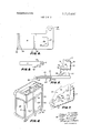
- FIG. 4 is a broken perspective of the locker with the tambour door removed and with the horizontal swinging door substituted therefor;
- FIG. 5 is a fragmentary cross-sectional view taken along plane V-V of FIG. 4, with the door being shown exploded away from the hinge;
- FIG. 6 is a plan view of the hinge
- FIG. 7 is a broken, fragmentary view of the lower hinged corner of a horizontal swinging door.
- FIG. 8 is a fragmentary, bottom plan view of that portion of the door shown in FIG. 7.
- the locker 1 includes intelligence for mounting a sliding tambour door 40 in the form of tracks 30 in sidewalls 20 (FIG. 1).
- Locker I also includes snap-on hinges 50 (FIG. 4) to facilitate the mounting of horizontally opening doors 70.
- Cross pieces 60 (FIG. 4) are mounted in apertures 21 near the top and bottom of sidewalls 20.
- a pair of hinges 50 then snap on to cross piece 60, one near each sidewall 20.
- Door is carried between spaced top and bottom hinges 50" and includes a latch 76 (FIG. 5) for cooperating with a catch 55 on each of the top and bottom hinges 50 located adjacent each sidewall 20.
- the components of locker l are molded of some type of plastic which is rugged, sturdy, and readily cleanable.
- the plastic sidewalls 20 depend forwardly from each side of back 10 (FIG. 1).
- Each sidewall 20 includes integrally molded drawer glides 23 of the type disclosed and claimed in co-pending U.S. Pat. application, Ser. No. 79,890.
- Back 10 includes an outwardly and downwardly projecting hook I] and rearwardly projecting feet 12 whereby the entire locker 1 can be hung on a rail secured to a wall or the like.
- Drawers, shelves, trays, and the like can then be mounted in locker l by placing them between opposite sets of glides 23.
- Each sidewall 20 includes a track 30 in which vertically sliding tambour door 40 is mounted (FIGS. 1 and 2).
- Track 30 comprises a groove or channel which is preferably integrally molded into sidewall 20.
- Track 30 extends from the top of each sidewall 20, vertically down almost to the bottom, whereit bends around and extends rearwardly near the bottom of sidewall 20 and then curves upwardly near the back edge of sidewall 20 (FIG. 3).
- a bottom retaining notch 32 is formed by a jogging deviation in the forward face of track 30 near the bottom front corner, for the purpose of providing a means for holding tambour door 40 in an open position as shown in FIG. 1.
- an upper retaining notch 31 is cut into the rear face of track 30 at the top thereof for holding tambour door 40 in a closed position as shown in FIG. 2.
- tambour door 40 includes a flange 42' projecting inwardly from its top slat for purposes of hooking into upper retaining notch 31.
- Tambour door 40 is itself comprised of a plurality of slats 41 (FIG. 2). While many types of conventional tambour type doors are acceptable, the preferred type is that which is integrally molded of flexible plastic material. Because of this one piece construction, the door is readily washable. The door is purposely molded with joints, of narrow cross section, between wider segments which constitute the slats 41.
- track 30 has an open end 33 at the top thereof. This facilitates the complete removal of tambour door 40 when it is desired to substitute horizontally swinging doors 70 therefor.
- each sidewall 20 includes intelligence to facilitate the installation of releasably mounted snap-on hinges 50.
- Each sidewall 20 includes an elongated aperture 21 at the top front and at the bottom front thereof (FIG. 3).
- a slightly flexible plastic cross piece 60 can be snapped into the top apertures 21 and into the bottom apertures 21 of opposite sidewalls 20 such that they span the width of locker 1 (FIG. 4).
- Such cross pieces 60 provide added rigidity and stability to locker 1.
- the snap-on hinges 50 can be snapped into position on each cross piece 60 adjacent each sidewall 20 (FIG. 4).
- Each sidewall 20 also includes a longer elongated slot 22, just to the rear of aperture 21.
- the primary function of slot 22 is to effectuate economy in material by making it possible to use less plastic.
- Each hinge 50 is molded of plastic and comprises a generally flat platform 51 (FIG. 6) having a pair of spaced, slightly resilient channel walls 52 projecting from one face thereof (FIG.
- Each channel wall 52 includes a channel lip 53, both channel lips 53 curving inwardly from channel wall 52 towards one another. I-Iinge 50 can be snapped over cross piece 60 with channel walls 52 embracing the edges thereof and with channel lips 53 over-lapping the bottom thereof to thereby provide a snug mechanical fit between cross piece 60 and hinge 50.
- each platform 51 includes a hinge pin 54 projecting upwardly therefrom (FIG. 5). This could project from the same face of platform 51 as channel walls 52, but it is preferable from a structural standpoint that it project from an opposite face.
- each bottom hinge 50 can be placed on top of cross piece 60 with channel walls 52 depending downwardly and hinge pin 54 depending upwardly. If hinge pin 54 and channel walls 52 were oriented on the same face of platform 51, then the bottom hinge 50 would hang from cross piece 60 rather than rest thereon and would have a greater tendency to be snapped off by the weight of door 70.
- top hinges there is no necessity for constructing the top hinges this way since they do not bear any weight.
- economy dictates that a hinge suitable for use at the bottom adjacent one side be suitable for use at the top adjacent the other side. Thus, only two basic hinges need be manufactured.
- hinge 50 is generally L-shaped and that hinge pin 54 is located on a laterally extending portion 51a of platform 51. This allows one to hang door 70 in direct alignment with the edges a (FIGS. 1 and 2) of sidewalls 20 such that r they provide coverage for edges 20a as shown in FIG.
- Platform 51 is sufficiently long that laterally extending portion 51a does extend out in front of the edge of sidewall 20 when bracket 50 is mounted on cross piece 60.
- each hinge 50 is slid along cross piece 60 until it abuts sidewall 20, with the result that laterally extending portion 51a will be positioned in front of the front edge 20a of sidewall 20.
- Door 70 is economically molded ofa suitable plastic, such that it has a relatively thin cross section throughout. Thus, it includes an edge wall 71 extending around its entire periphery (FIGS. 4 and 7). Extending inwardly from each edge wall 71, in a generally vertical plane, is a boarder wall 72 which frames a recessed face panel 74. An inwardly projecting recess wall 73 joins boarder wall 72 with face panel 74.
- This series of peripheral walls, i.e., edge wall 71, boarder wall 72, and recess wall 73, disposed angularly with respect to one another, provide door 70 with structural strength and rigidity.
- Each door 70 includes an aperture 75 (FIGS. 5, 7 and 8) which slips down over hinge pin 54. Hinge pin 54 extends through aperture 75.
- edge wall 71 depends rearwardly from front boarder wall 72 renders it possible to design edge wall 71 of a'suflicient width that aperture 75 can be included therein for accommodating hinge pin 54.
- boarder wall 72 is made sufficiently wide, before joining recess wall 73, that an upwardly projecting hinge pin 54 does not run into or abut recess wall 73 when door 70 is mounted in place in the locker. While an aperture 75 is shown only at the bottom corner of door 70, it will be appreciated that such an aperture 75 is also included at the top edge wall 71 of door 70 adjacent the side edge of the door.
- each door can be hingedly mounted between each pair of spaced top and bottom hinges 50 by mounting the hinges 50 with their hinge pins 54 extending in through apertures of door 70.
- the doors 70 are all symmetrical in design such that a right hand door can be used as a left hand door merely by inverting it.
- Each hinge 50 includes an integral catch 55 for cooperating with a latch 76 on each door 70 (FIGS. 5 and 7). While it may only be necessary to have one catch 55 and latch 76 for each door 70, it is preferable that such cooperating catch and latch members be positioned both at the top and at the bottom of each door 70 to insure their proper closure.
- Catch 55 comprises a resilient member 56 projecting from the same face of platform 51 as does hinge pin 54 (FIGS. 5 and 6). Resilient member 56 projects upwardly in a direction towards the front of hinge 50, i.e., towards door 70. At a point spaced from the surface of platform 51 it juts back downwardly towards platform 51 to define a catch lip 57.
- Latch 76 includes a resilient projection 77, projecting rearwardly from bottom edge wall 71 to a position between the surface of platform 51 and catch lip 57 (FIGS. 5 and 7). At that point, it juts upwardly defining a hook 78 which engages "catch lip 57 to hold door 70 in a closed position. While this cooperation is not directly shown, it can be readily visualized by viewing the exploded view, FIG. 5.
- resilient member 56 By applying a slight outward pressure to the door 70, resilient member 56 will be bent upwardly and rearwardly, and hook 78 will slide past catch lip 57 such that door 70 can be opened. Some deflection may also occur in resilient projection 77 of latch 78. However, the fact that resilient member 56 is disposed at an acute angle to the horizontal plane through which door 70 is opened renders it more susceptible to such resilient bending motion.
- locker 1 can be provided either with tambour door 40 or with horizontally swinging doors 70. if tambour door 40 is used, locker 1 can be closed by sliding tambour door 40 all the way up in track 30 and hooking flange 42 into top retaining notch 31. In order to open tambour door 40, it can be slid downwardly and up the back side of locker 1 until the leading edge of its top slat 41 can be hooked into lower retaining notch 32:
- tambour door 40 can be slid all the way up and out of the open end 33 of track 30.
- a cross piece 60' can then be inserted at the top and at the bottom of locker 1, utilizing elongated apertures 21 at the top and bottom of each sidewall 20.
- the hinges 50 can then be snapped on to cross piece 60 such that one hinge50 is located adjacent each sidewall at the top and at the bottom thereof.
- the channel walls 52 of each hinge "5 0 will embrace the. sides of cross piece 60, and the lips 53 will overlap cross piece 60 to firmly holdeach hinge 50 in place thereon.
- hinge pin 54 will be received in the holes 75 located in the wall 71 at the top and in the edge wall 71 at the bottomof door 70 near the side of door 70. in this manner each door 70 will swing freely horizontally on hinge pins 54.
- each door 70 will cooperate with the corresponding catch 55 which is an integral part of each hinge 50.
- the hook 78 of each rearwardly projecting latch 76 will be engaged bythe catch lip 57 of each catch 55.
- the resilient member 56 of each catch 55 will bend upwardly and backwardly, thus allowing hook 78 to snap past catch lip 57, thereby allowingdoor 70 to be opened.
- this invention contributes a locker with increased versatility andv use.
- the same basic locker-can be manufactured for use as aswinging door locker or as a tambour door locker. This effectuates an economy in manufacturing and makes it easier for institutions to adjust to their changing requirements.
- a locker comprising: a back wall and two sidewalls depending forwardly therefrom; means on each of said sidewalls for slidably receivinga vertically sliding door; means on said sidewalls for removing said vertically sliding door; means on at least one of said sidewalls for operably receivinghinges upon which a horizontally opening door can be mounted; hinges for operably and releasably mechanically cooperating with said hinge receiving means on said sidewalls; at least one horizontally opening door having means for cooperating with said hinges whereby said horizontally opening door can be mounted on the front of said locker in place of said vertically sliding door.
- said means for slidably receiving said vertically sliding door comprises a track in said sidewall extending at least from the top to the bottom thereof; said means for removing said vertically sliding door comprising said track having at least one open end out of which said vertically sliding door can be removed.
- a locker comprising: a back wall and two sidewalls depending forwardly therefrom; means on each of said sidewalls for slidably receiving a vertically sliding door; means on said sidewalls for removing said vertically sliding door; means for operably receiving hinges upon' which a horizontally opening door can be mounted, said means including an elongated aperture near the top and bottom of each of said sidewalls and a pair of generally flat cross pieces, one for positioning at the top and one forpositioning at the bottom.
- said cross pieces having a length slightly greater than the width of said locker such that their ends can be inserted into said elongated apertures of said sidewalls with said cross pieces spanning the width of said locker; hinges for operably and releasably mechanically cooperating with said hinge receiving means on said sidewalls, wherein said hinges include means for mechanically interfitting with said cross pieces, adjacent said sidewalls; at least one horizontally opening door having means for cooperating with said hinges whereby said horizontally opening door can be mounted on the front of said locker in place of said vertically sliding door.
- said means of said hinge for mechanically interfitting with said cross pieces comprises a platform having spaced channel walls projecting from one face thereof for embracing the opposite sides of said cross piece, said channel walls having lips thereon for wrapping around said cross piece to thereby hold said hinge firmly in place; said platform of at least one of said hinges including a resilient member projecting upwardly therefrom towards said door and then jutting downwardly back towards said platform to define a catch lip; said door includinga latch projecting rearwardly'therefrom to a position between said resilient member and said platform and then jutting upwardly to define a hook for cooperating with said catch lip whereby said door can be maintained in a closed position.
- a locker comprising: a back wall and two sidewalls projecting forwardlytherefrom; at least one hinge at the top and at least one hinge at the bottom of said locker, adjacent one of saidsidewalls; a door pivotally mounted on said hinges; at least one of said hinges including a platform extending away from said sidewall; a catch mounted on said platform; said catch comprising a yieldingly resilient member projecting upwardly from said platform towards said door and having a lip thereon which extends downwardly back towards said platform; said door including a latch positioned opposite said catch for mating engagement therewith, said latch projecting rearwardly from said door to a position between said yieldingly resilient member and said platform and then hooking upwardly to define a hook for mating engagement with said lip whereby said door is held in a closed position, but can be opened by pulling thereon, causing said yieldingly resilient member to bend upwardly and rearwardly and thereby allowing said hook to snap past said lip.
- said platform is generally L-shaped, having a first portion extending forwardly to the front edge of said sidewall and a second portion which extends laterally therefrom, out in front of the front edge of said sidewall; a hinge pin projecting from said second portion in front of said front edge of said sidewall, to facilitate pivotal mounting of a door; said door including an aperture in its top edge and in its bottom edge into which said hinge pin projects.
- a cross piece spans the width of said locker at the top and bottom thereof; said first portion of said hinge platform being secured to one of said cross pieces.
- a locker comprising: a back wall and two sidewalls projecting forwardly therefrom; a track in each of said sidewalls at the front thereof, extending generally from the top of said locker to its bottom, for receiving a vertically sliding tambour door; each of said tracks having an open end whereby said tambour door can be removed from said locker; each of said sidewalls including means at the top and at the bottom thereof for releasably receiving a cross piece; a cross piece at the top and at the bottom of said locker, extending between said sidewalls and being releasably mounted in said cross piece receiving means; a hinge for mounting on each of said cross pieces adjacent at least one of said sidewalls; said hinge comprising a platform with spaced channel walls depending from one face thereof for embracing said cross bar; said channel walls having inwardly turning lips thereon and being slightly resilient whereby said platform can be snapped on to or off of said cross piece; at least one horizontally opening door for said locker; means on each of said platforms for hinfor cooperating with a latch on said door
- said means on said platform for hingedly mounting said door comprises a hinge pin projecting from one surface thereof; said hinge pin projecting from a surface of said platform 0 osite said surface fro which said hannel walls pr gject, at least on said h inge positioned at the bottom of said locker, whereby said hinge at the bottom of said locker snaps onto the top of said cross piece with said hinge pin projecting upwardly towards mating engagement with an aperture in the bottom edge of said door.
- said platform is generally L-shaped, having a first portion and a second portion projecting laterally therefrom; said first portion projecting from said cross piece out to the front edge of said sidewall; said second portion projecting laterally out in front of said front edge of said sidewall; said hinge pin projecting from the surface of said second portion of said platform.
- said cross piece receiving means comprise elongated apertures in said sidewalls at the tops and bottoms thereof; said cross piece being a generally flat, slightly flexible elongated member having a length slightly greater than the width of said locker whereby it must be flexed slightly for insertion into said apertures in said sidewalls.
- said catch mounted on said hinge comprises a yieldingly resilient member projecting upwardly from said platform towards said door and having a catch lip thereon which extends downwardly back towards said platform; said door latch being positioned opposite said catch for mating engagement therewith and projecting rearwardly from said door to a position between said yieldingly resilient member and said platform, and then hooking upwardly to define a hook for mating engagement with said catch lip whereby said door is held closed, but can be opened by pulling thereon, causing said yieldingly resilient member to bend upwardly and rearwardly, thus allowing said hook to snap past said lip.
Landscapes
- Engineering & Computer Science (AREA)
- Structural Engineering (AREA)
- Civil Engineering (AREA)
- Architecture (AREA)
- Hinges (AREA)
- Extensible Doors And Revolving Doors (AREA)
- Cabinets, Racks, Or The Like Of Rigid Construction (AREA)
Applications Claiming Priority (1)
| Application Number | Priority Date | Filing Date | Title |
|---|---|---|---|
| US14916471A | 1971-06-02 | 1971-06-02 |
Publications (1)
| Publication Number | Publication Date |
|---|---|
| US3712697A true US3712697A (en) | 1973-01-23 |
Family
ID=22529050
Family Applications (1)
| Application Number | Title | Priority Date | Filing Date |
|---|---|---|---|
| US00149164A Expired - Lifetime US3712697A (en) | 1971-06-02 | 1971-06-02 | Locker |
Country Status (10)
| Country | Link |
|---|---|
| US (1) | US3712697A (show.php) |
| JP (1) | JPS5536791B1 (show.php) |
| AR (1) | AR193075A1 (show.php) |
| BE (1) | BE783011A (show.php) |
| BR (1) | BR7202219D0 (show.php) |
| CA (1) | CA963056A (show.php) |
| CH (1) | CH547071A (show.php) |
| DE (1) | DE2224327C3 (show.php) |
| FR (1) | FR2141674B1 (show.php) |
| GB (2) | GB1358805A (show.php) |
Cited By (31)
| Publication number | Priority date | Publication date | Assignee | Title |
|---|---|---|---|---|
| US3812999A (en) * | 1970-06-11 | 1974-05-28 | Reunis Sa Ateliers | Crate |
| US3814493A (en) * | 1972-11-24 | 1974-06-04 | Universal Oil Prod Co | Plastic tambour door |
| US4084125A (en) * | 1975-05-19 | 1978-04-11 | King James R | Mobile shelving unit |
| US4140356A (en) * | 1977-04-27 | 1979-02-20 | Comerco, Inc. | Storage unit |
| US4270816A (en) * | 1979-01-23 | 1981-06-02 | Interface Design Group, Inc. | Furniture having prestressed fabric panels |
| US4320935A (en) * | 1979-10-22 | 1982-03-23 | Herman Miller, Inc. | Structural support system with load control |
| US4441768A (en) * | 1982-03-16 | 1984-04-10 | Thatchcode Limited | Office cabinet |
| US5011240A (en) * | 1989-11-28 | 1991-04-30 | Milcare, Inc. | Segmented side wall cart |
| USD322875S (en) | 1990-06-20 | 1991-12-31 | Milcare, Inc. | Cart or the like |
| USD325800S (en) | 1990-05-09 | 1992-04-28 | Milcare, Inc. | Cart or the like |
| US5803563A (en) * | 1997-07-11 | 1998-09-08 | National Products, Incorporated | Cabinet with removable tambour door |
| WO1998025569A3 (en) * | 1996-12-10 | 1999-01-07 | Miller Herman Inc | Endoscope cabinet |
| USD437149S1 (en) | 2000-07-18 | 2001-02-06 | Karl Klenk Mobelfabrik Gmbh | Cabinet |
| USD472732S1 (en) | 2001-09-19 | 2003-04-08 | Vitra Patente Ag | Office furniture |
| JP3525317B2 (ja) | 1996-11-27 | 2004-05-10 | 株式会社岡村製作所 | 商品陳列棚 |
| JP3533550B2 (ja) | 1996-11-27 | 2004-05-31 | 株式会社岡村製作所 | 商品陳列棚 |
| US20050016080A1 (en) * | 2003-06-12 | 2005-01-27 | Williams Otto N. | Office system |
| USD568631S1 (en) | 2007-06-05 | 2008-05-13 | Steelcase Development Corp. | Cabinet |
| USD587034S1 (en) | 2007-06-08 | 2009-02-24 | Steelcase Development Corporation | Cabinet |
| USD587033S1 (en) | 2007-06-04 | 2009-02-24 | Steelcase Development Corporation | Cabinet |
| WO2013016763A1 (en) * | 2011-07-29 | 2013-02-07 | Fsp Holdings Pty Ltd | Improvements in lockers |
| US20140017001A1 (en) * | 2011-03-28 | 2014-01-16 | Unilin Bvba | Composed Element and Rear Wall Construction Applied Herewith |
| US20140225485A1 (en) * | 2008-11-17 | 2014-08-14 | Versatility Tool Works & Manufacturing Company | Tool cabinet with downward opening transparent front door |
| USD745298S1 (en) * | 2014-03-03 | 2015-12-15 | L&P Property Management Company | Modular shelving assembly |
| US9346391B2 (en) | 2013-03-06 | 2016-05-24 | L&P Property Management Company | Modular shelving assembly |
| US9398806B2 (en) * | 2014-09-29 | 2016-07-26 | Eagle Manufacturing Company | Snap together safety storage cabinet |
| US9872562B2 (en) * | 2013-02-05 | 2018-01-23 | Keter Plastic Ltd. | Cabinet |
| USD855360S1 (en) * | 2015-04-10 | 2019-08-06 | Apex Industrial Technologies Llc | Display rack for bins |
| US20190365094A1 (en) * | 2018-09-18 | 2019-12-05 | Sam Allen | Locker with Reclining Seat and Roll-Up Door |
| US20240108132A1 (en) * | 2021-07-08 | 2024-04-04 | E.B. Endres, Inc. | Anti-ligature wardrobe |
| US12376678B1 (en) | 2019-07-18 | 2025-08-05 | Aim Design, Llc | Locker with reclining seat and roll-up door |
Citations (6)
| Publication number | Priority date | Publication date | Assignee | Title |
|---|---|---|---|---|
| US2024493A (en) * | 1933-12-18 | 1935-12-17 | Stewart Warner Corp | Refrigerator evaporator door |
| US2683891A (en) * | 1953-04-10 | 1954-07-20 | Eastern Venetian Blind Company | Drapery traverse rod assembly |
| US2835359A (en) * | 1955-05-09 | 1958-05-20 | American Radiator & Standard | Door and hinge structure |
| US3278980A (en) * | 1964-07-13 | 1966-10-18 | Drapery Hardware Mfg Co | Folding door mounting assembly and bracket therefor |
| US3330611A (en) * | 1965-08-16 | 1967-07-11 | Sidney T Heifetz | Mobile bulk-storage compartment carts |
| US3424510A (en) * | 1967-06-05 | 1969-01-28 | Lakeside Mfg Inc | Display carts with bubble tops |
-
1971
- 1971-06-02 US US00149164A patent/US3712697A/en not_active Expired - Lifetime
-
1972
- 1972-02-23 CA CA135,387A patent/CA963056A/en not_active Expired
- 1972-03-24 AR AR241121A patent/AR193075A1/es active
- 1972-03-29 JP JP3153772A patent/JPS5536791B1/ja active Pending
- 1972-04-14 BR BR722219A patent/BR7202219D0/pt unknown
- 1972-04-17 GB GB3749973A patent/GB1358805A/en not_active Expired
- 1972-04-17 GB GB1762072A patent/GB1358804A/en not_active Expired
- 1972-05-02 FR FR727215489A patent/FR2141674B1/fr not_active Expired
- 1972-05-04 BE BE783011A patent/BE783011A/xx unknown
- 1972-05-18 DE DE2224327A patent/DE2224327C3/de not_active Expired
- 1972-05-29 CH CH789972A patent/CH547071A/xx not_active IP Right Cessation
Patent Citations (6)
| Publication number | Priority date | Publication date | Assignee | Title |
|---|---|---|---|---|
| US2024493A (en) * | 1933-12-18 | 1935-12-17 | Stewart Warner Corp | Refrigerator evaporator door |
| US2683891A (en) * | 1953-04-10 | 1954-07-20 | Eastern Venetian Blind Company | Drapery traverse rod assembly |
| US2835359A (en) * | 1955-05-09 | 1958-05-20 | American Radiator & Standard | Door and hinge structure |
| US3278980A (en) * | 1964-07-13 | 1966-10-18 | Drapery Hardware Mfg Co | Folding door mounting assembly and bracket therefor |
| US3330611A (en) * | 1965-08-16 | 1967-07-11 | Sidney T Heifetz | Mobile bulk-storage compartment carts |
| US3424510A (en) * | 1967-06-05 | 1969-01-28 | Lakeside Mfg Inc | Display carts with bubble tops |
Cited By (46)
| Publication number | Priority date | Publication date | Assignee | Title |
|---|---|---|---|---|
| US3812999A (en) * | 1970-06-11 | 1974-05-28 | Reunis Sa Ateliers | Crate |
| US3814493A (en) * | 1972-11-24 | 1974-06-04 | Universal Oil Prod Co | Plastic tambour door |
| US4084125A (en) * | 1975-05-19 | 1978-04-11 | King James R | Mobile shelving unit |
| US4140356A (en) * | 1977-04-27 | 1979-02-20 | Comerco, Inc. | Storage unit |
| US4270816A (en) * | 1979-01-23 | 1981-06-02 | Interface Design Group, Inc. | Furniture having prestressed fabric panels |
| US4320935A (en) * | 1979-10-22 | 1982-03-23 | Herman Miller, Inc. | Structural support system with load control |
| US4441768A (en) * | 1982-03-16 | 1984-04-10 | Thatchcode Limited | Office cabinet |
| US5011240A (en) * | 1989-11-28 | 1991-04-30 | Milcare, Inc. | Segmented side wall cart |
| USD325800S (en) | 1990-05-09 | 1992-04-28 | Milcare, Inc. | Cart or the like |
| USD322875S (en) | 1990-06-20 | 1991-12-31 | Milcare, Inc. | Cart or the like |
| JP3525317B2 (ja) | 1996-11-27 | 2004-05-10 | 株式会社岡村製作所 | 商品陳列棚 |
| JP3533550B2 (ja) | 1996-11-27 | 2004-05-31 | 株式会社岡村製作所 | 商品陳列棚 |
| WO1998025569A3 (en) * | 1996-12-10 | 1999-01-07 | Miller Herman Inc | Endoscope cabinet |
| US5803563A (en) * | 1997-07-11 | 1998-09-08 | National Products, Incorporated | Cabinet with removable tambour door |
| USD437149S1 (en) | 2000-07-18 | 2001-02-06 | Karl Klenk Mobelfabrik Gmbh | Cabinet |
| USD472732S1 (en) | 2001-09-19 | 2003-04-08 | Vitra Patente Ag | Office furniture |
| US20050016080A1 (en) * | 2003-06-12 | 2005-01-27 | Williams Otto N. | Office system |
| US7707790B2 (en) | 2003-06-12 | 2010-05-04 | Steelcase Inc. | Office system |
| US20100205868A1 (en) * | 2003-06-12 | 2010-08-19 | Williams Otto N | Office system |
| USD587033S1 (en) | 2007-06-04 | 2009-02-24 | Steelcase Development Corporation | Cabinet |
| USD568631S1 (en) | 2007-06-05 | 2008-05-13 | Steelcase Development Corp. | Cabinet |
| USD587034S1 (en) | 2007-06-08 | 2009-02-24 | Steelcase Development Corporation | Cabinet |
| US20140225485A1 (en) * | 2008-11-17 | 2014-08-14 | Versatility Tool Works & Manufacturing Company | Tool cabinet with downward opening transparent front door |
| US9089963B2 (en) * | 2008-11-17 | 2015-07-28 | Versatility Tool Works & Manufacturing Company | Tool cabinet with downward opening transparent front door |
| US9781997B2 (en) * | 2011-03-28 | 2017-10-10 | Unilin Bvba | Composed element and rear wall construction applied herewith |
| US12313106B2 (en) | 2011-03-28 | 2025-05-27 | Unilin, Bv | Composed element and rear wall construction applied herewith |
| US20140017001A1 (en) * | 2011-03-28 | 2014-01-16 | Unilin Bvba | Composed Element and Rear Wall Construction Applied Herewith |
| US10570938B2 (en) | 2011-03-28 | 2020-02-25 | Unilin, Bvba | Composed element and rear wall construction applied herewith |
| US12018706B2 (en) | 2011-03-28 | 2024-06-25 | Unilin Bv | Composed element and rear wall construction applied herewith |
| US11668335B2 (en) | 2011-03-28 | 2023-06-06 | Flooring Industries Limited, Sarl | Composed element and rear wall construction applied herewith |
| US9113704B2 (en) | 2011-07-29 | 2015-08-25 | FSP Holdings Pty. Ltd. | Lockers |
| CN103796552A (zh) * | 2011-07-29 | 2014-05-14 | Fsp控股私人有限公司 | 储物阁的改进 |
| RU2597583C2 (ru) * | 2011-07-29 | 2016-09-10 | ЭфЭсПи ХОЛДИНГЗ ПТИ ЛТД | Улучшения запирающихся ящиков |
| CN103796552B (zh) * | 2011-07-29 | 2016-10-12 | Fsp控股私人有限公司 | 储物阁的改进 |
| WO2013016763A1 (en) * | 2011-07-29 | 2013-02-07 | Fsp Holdings Pty Ltd | Improvements in lockers |
| US9872562B2 (en) * | 2013-02-05 | 2018-01-23 | Keter Plastic Ltd. | Cabinet |
| US10046719B2 (en) | 2013-03-06 | 2018-08-14 | Masterack Manufacturing And Installation, Llc | Modular shelving assembly |
| US9346391B2 (en) | 2013-03-06 | 2016-05-24 | L&P Property Management Company | Modular shelving assembly |
| USD745298S1 (en) * | 2014-03-03 | 2015-12-15 | L&P Property Management Company | Modular shelving assembly |
| USD894654S1 (en) | 2014-03-03 | 2020-09-01 | Masterack Manufacturing And Installation, Llc | Modular shelving assembly |
| US9398806B2 (en) * | 2014-09-29 | 2016-07-26 | Eagle Manufacturing Company | Snap together safety storage cabinet |
| USD855360S1 (en) * | 2015-04-10 | 2019-08-06 | Apex Industrial Technologies Llc | Display rack for bins |
| US11382423B2 (en) * | 2018-09-18 | 2022-07-12 | Aim Design, Llc | Locker with reclining seat and roll-up door |
| US20190365094A1 (en) * | 2018-09-18 | 2019-12-05 | Sam Allen | Locker with Reclining Seat and Roll-Up Door |
| US12376678B1 (en) | 2019-07-18 | 2025-08-05 | Aim Design, Llc | Locker with reclining seat and roll-up door |
| US20240108132A1 (en) * | 2021-07-08 | 2024-04-04 | E.B. Endres, Inc. | Anti-ligature wardrobe |
Also Published As
| Publication number | Publication date |
|---|---|
| BR7202219D0 (pt) | 1973-06-07 |
| DE2224327A1 (de) | 1972-12-14 |
| JPS5536791B1 (show.php) | 1980-09-24 |
| FR2141674B1 (show.php) | 1973-07-13 |
| GB1358805A (en) | 1974-07-03 |
| GB1358804A (en) | 1974-07-03 |
| AR193075A1 (es) | 1973-03-30 |
| FR2141674A1 (show.php) | 1973-01-26 |
| DE2224327C3 (de) | 1980-10-23 |
| CA963056A (en) | 1975-02-18 |
| BE783011A (fr) | 1972-09-01 |
| DE2224327B2 (show.php) | 1980-02-28 |
| CH547071A (de) | 1974-03-29 |
Similar Documents
| Publication | Publication Date | Title |
|---|---|---|
| US3712697A (en) | Locker | |
| US3752553A (en) | Drawer with snap-on front panel | |
| US3023068A (en) | Storage cabinet | |
| US5403084A (en) | Molded refrigerator shelf with snap-in slide | |
| US4134625A (en) | Bathroom cabinet | |
| US3909088A (en) | Cassette receptacle and storage apparatus | |
| US3295471A (en) | Folding-shelf | |
| CA1102745A (en) | Shelf display system | |
| US3110533A (en) | Combination cabinet bar unit | |
| US4925258A (en) | Office cabinet with flipper door and interlocking drawer and suspension assemblies | |
| CN106031563B (zh) | 柜子 | |
| US2667401A (en) | Convertible cabinet | |
| US3298764A (en) | Cabinet | |
| US2269940A (en) | Storage device | |
| CA2140592A1 (en) | Cantilever slide-out refrigerator basket | |
| US3938871A (en) | Cassette storage device with adjustable partitions | |
| US3292983A (en) | Sink drawer | |
| US3529382A (en) | Wide opening sliding door construction for a lawn building or the like | |
| US4388935A (en) | Hingeless compact | |
| US4236772A (en) | Storage system | |
| US3620588A (en) | Door closure for shelving | |
| US10716414B2 (en) | Rotatable picture frame | |
| US4141110A (en) | Hinge arrangement | |
| US4492418A (en) | Lateral filing drawers | |
| US4884854A (en) | Interconnecting panels for knockdown structures |