US3711159A - Tunnelling machines - Google Patents
Tunnelling machines Download PDFInfo
- Publication number
- US3711159A US3711159A US00109496A US3711159DA US3711159A US 3711159 A US3711159 A US 3711159A US 00109496 A US00109496 A US 00109496A US 3711159D A US3711159D A US 3711159DA US 3711159 A US3711159 A US 3711159A
- Authority
- US
- United States
- Prior art keywords
- shield
- jaws
- excavating
- jaw
- arcuate
- Prior art date
- Legal status (The legal status is an assumption and is not a legal conclusion. Google has not performed a legal analysis and makes no representation as to the accuracy of the status listed.)
- Expired - Lifetime
Links
- 238000005520 cutting process Methods 0.000 claims abstract description 22
- NMFHJNAPXOMSRX-PUPDPRJKSA-N [(1r)-3-(3,4-dimethoxyphenyl)-1-[3-(2-morpholin-4-ylethoxy)phenyl]propyl] (2s)-1-[(2s)-2-(3,4,5-trimethoxyphenyl)butanoyl]piperidine-2-carboxylate Chemical compound C([C@@H](OC(=O)[C@@H]1CCCCN1C(=O)[C@@H](CC)C=1C=C(OC)C(OC)=C(OC)C=1)C=1C=C(OCCN2CCOCC2)C=CC=1)CC1=CC=C(OC)C(OC)=C1 NMFHJNAPXOMSRX-PUPDPRJKSA-N 0.000 description 3
- 229930182714 Excavatin Natural products 0.000 description 1
- 238000009412 basement excavation Methods 0.000 description 1
- 230000015572 biosynthetic process Effects 0.000 description 1
- 230000002860 competitive effect Effects 0.000 description 1
- 238000005755 formation reaction Methods 0.000 description 1
- 238000009434 installation Methods 0.000 description 1
- 230000036346 tooth eruption Effects 0.000 description 1
Images


Classifications
-
- E—FIXED CONSTRUCTIONS
- E21—EARTH OR ROCK DRILLING; MINING
- E21D—SHAFTS; TUNNELS; GALLERIES; LARGE UNDERGROUND CHAMBERS
- E21D9/00—Tunnels or galleries, with or without linings; Methods or apparatus for making thereof; Layout of tunnels or galleries
- E21D9/06—Making by using a driving shield, i.e. advanced by pushing means bearing against the already placed lining
- E21D9/08—Making by using a driving shield, i.e. advanced by pushing means bearing against the already placed lining with additional boring or cutting means other than the conventional cutting edge of the shield
Definitions
- ABSTRACT A tunnelling machine more particularly but not exclu sively intended to operate in soft ground, comprises a tubular cutting and protection shield which is periodically advanced with reference to a base or an already erected section of tunnel lining and is preferably characterized by the provision at the forward end of the shield of a pair of cutter-carrying excavating jaws which are power operated and swin'gable in arcuate excavating paths about parallel axes from retracted positions inside the shield to positions projecting for wardly thereof wherein the jaws are closed upon one another.
- This invention relates to tunnelling machines of the kind which are more particularly but not exclusively intended to operate in soft ground and which usually comprise a tubular cutting and protection shield which is periodically advanced with reference to a base or an already erected section of the tunnel lining.
- Relatively large'machines of the kind referred to are commonly provided with a rotary cutter or excavator which is co-axial with the shield and some form of mechanical conveyor is provided for removing the spoil.
- Such machines are expensive and not usually justified, or available, for cutting relatively small diameter tunnels having a diameter of the order of for instance 6 feet.
- small bore tunnelling machines usually only comprise a cylindrical shield with a cutting edge, excavation and spoil removal being effected manually there being only a relatively small space available for any extra cutter and/or mechanical conveyor.
- the cutting rate of such machines is therefore inevitably slow, particularly in wet ground, and the cost of manual labor is high.
- the object of the invention is to provide a more efficient and rapid tunnelling machine particularly but not necessarily of relatively small size having improved and relatively inexpensive excavating means which occupies less space within theshield and which facilitates installation of a spoil removal conveyor.
- a tunnelling machine of the kind referred to comprises at the forward end of the shield .a pair of excavating, cutter carrying, pivoted jaws which are power operated and movable towards and away from one another to excavate the material ahead of but within the confines of the cutting edge of the shield.
- FIG. 1 is a fragmentary isometric view of the forward end of the tunnellingmachine
- FIG. 2 is a frontal elevation of the tunnelling machine
- FIG. 3 is a section on line A-A of FIG. 2;
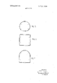
- F IG. 4 is a section on line B-B of FIG. 2; whilst FIGS. 5, 6 and 7 illustrate different excavating jaw formations for alternative tunnel shapes.
- the tunnelling machine shown in FIGS. 1 to 4 comprises a cylindrical shield l with a front cutting edge 2 situated in a diametric plane.
- the shield 1 is equipped internally with two or more main thrust rams 3 which operate between an internal annular abutment flange 4 forming part of the shield and the leading end parts 5 of an already inserted tunnel lining section.
- the latter may for instance be comprisedof arcuate concrete sections.
- the rams are hydraulically operated and periodically advanced, retracted and adjusted in the usual manner.
- a pair of semi-circular excavating jaws 6, 6' are mounted on individual parallel shafts 7 situated one each side of and perpendicular to the center axis of the shield. These shafts 7 are normally vertical and when the jaws 6, 6' are fully open they lie in a diametric plane and concentrically adjacent the inside surface of the shield 1.
- the excavating jaw 6 is shown in such a position.
- the excavating jaws 6, 6' carry a series of forwardly directed digging teeth 8 dimensioned and spaced to suit ground conditions. Alternatively discs or other cutters could be fitted.
- the jaws 6, 6' In their fully closed positions the jaws 6, 6' project I forwardly of the shield 2 and lie in planes parallel with the shield axis with the teeth 8 in engagement. In the drawings the jaw 6' is shown in such a position.
- the jaws are swung in unison between their fully open and fully closed positions by simultaneous extension of individual hydraulic rams 9 pivotally anchored within the shield and each pivotally connected to a frame portion 10 of a jaw intermediate its pivoted and its outward end.
- the jaw operating rams 9 would operate from the same hydraulic circuit as the main thrust rams.
- the other rams 9 are operated to close the jaws 6, 6' together. This closing movement causes the cutting teeth 8 on the jaws to scoop vor excavate a part spherical mass of material which is removed as spoil either manually or preferably by means of a small self loading endless belt ordrag bucket conveyor (not shown) operating longitudinally within the shield l.
- the excavating jaws 6, 6' and the rams 9 for operating them are preferably mounted so as to facilitate case respectively.
- the positions of the hydraulic rams are indicated by circles and it is to be noted that in FIG. 6 the jaws pivot about horizontal axes.
- the improved tunnelling machine is particularly intended for relatively small bore soft ground tunnelling, there appears to be no reason to suppose that the improved machine could not be commercially competitive inlarger sizes or be used also for tunnelling in relatively hard ground using differently designed cutters if necessary.
- a tunnelling machine comprising:
- each of said jaws having a centrally located operating arm which extends perpendicular to the plane of the jaw;
- said jaws being provided with teeth for cutting the earth.
- a soft ground tunnellingmachine comprising a tubular shield with a front cutting edge, at least one swingable jaw shaped to match part of the interior profile of said shield and having teeth on the front edge thereof, pivot means supporting said jaw so as to enable -to the axis of said shield and respectively supporting said jaw to turn in an arcuate path from a position in said jaws so as to enable said jaws to turn in arcuate the shield and positions in which they project forwardly thereof with their teeth closed together so as to excavate the ground, and hydraulic means mounted within said shield and coupled to said jaws for causing them to move in said arcuate paths.
- a tunnelling machine comprising a tubular cutting and protection shield having in its forward end an excavatin'g head comprising a pair of cutter-carrying excavating jaws which are power operated and swingable in arcuate excavating paths about parallel axes from retracted positions inside the shield to positions projecting forwardly thereof wherein the jaws are closed upon one another;
- excavating jaws are mounted from first flanged parts of the shield and are operable by individual, hydraulic rams anchored to second flanged parts of the shield.
- a tunnelling machine comprising a tubular cutting and protection shield having in its forward end an excavating head comprising a pair of cutter-carrying excavating jaws which are power operated and swingable in arcuate excavating paths about parallel axes from retracted positions inside the shield to positions projecting forwardly thereof wherein the jaws are closed upon one another;
- main hydraulic thrust rams operable between an internal flanged part shield and a rearward abutment.
Landscapes
- Engineering & Computer Science (AREA)
- Mining & Mineral Resources (AREA)
- Environmental & Geological Engineering (AREA)
- Life Sciences & Earth Sciences (AREA)
- General Life Sciences & Earth Sciences (AREA)
- Geochemistry & Mineralogy (AREA)
- Geology (AREA)
- Excavating Of Shafts Or Tunnels (AREA)
Applications Claiming Priority (1)
| Application Number | Priority Date | Filing Date | Title |
|---|---|---|---|
| GB29347/70A GB1278347A (en) | 1970-06-17 | 1970-06-17 | Improvements relating to tunnelling machines |
Publications (1)
| Publication Number | Publication Date |
|---|---|
| US3711159A true US3711159A (en) | 1973-01-16 |
Family
ID=10290106
Family Applications (1)
| Application Number | Title | Priority Date | Filing Date |
|---|---|---|---|
| US00109496A Expired - Lifetime US3711159A (en) | 1970-06-17 | 1971-01-25 | Tunnelling machines |
Country Status (4)
| Country | Link |
|---|---|
| US (1) | US3711159A (OSRAM) |
| DE (1) | DE2107930B2 (OSRAM) |
| FR (1) | FR2095482A5 (OSRAM) |
| GB (1) | GB1278347A (OSRAM) |
Cited By (5)
| Publication number | Priority date | Publication date | Assignee | Title |
|---|---|---|---|---|
| US5190407A (en) * | 1991-01-14 | 1993-03-02 | Kabushiki Kaisha Iseki Kaihatsu Koki | Rectangular shield excavating machine |
| US5538362A (en) * | 1992-10-08 | 1996-07-23 | Kabushiki Kaisha Iseki Kaihatsu Koki | Shield excavator |
| US20190376257A1 (en) * | 2017-01-18 | 2019-12-12 | Yubin Wang | Grooving Device for Underground Structures and Its Construction Method |
| US20190383142A1 (en) * | 2017-01-18 | 2019-12-19 | Yubin Wang | Tunneling Device for Pipe Jacking and Its Construction Method |
| US20220364469A1 (en) * | 2020-04-09 | 2022-11-17 | Shandong Jianzhu University | Composite support structure, construction system, and method |
Citations (3)
| Publication number | Priority date | Publication date | Assignee | Title |
|---|---|---|---|---|
| US752931A (en) * | 1904-02-23 | Tunneling apparatus | ||
| US1880091A (en) * | 1931-09-11 | 1932-09-27 | Charles R Hughes | Mining machine |
| US3446535A (en) * | 1966-03-19 | 1969-05-27 | Habegger Ag Maschf | Tunnel driving machine |
-
1970
- 1970-06-17 GB GB29347/70A patent/GB1278347A/en not_active Expired
-
1971
- 1971-01-25 US US00109496A patent/US3711159A/en not_active Expired - Lifetime
- 1971-02-19 FR FR7105686A patent/FR2095482A5/fr not_active Expired
- 1971-02-19 DE DE2107930A patent/DE2107930B2/de active Pending
Patent Citations (3)
| Publication number | Priority date | Publication date | Assignee | Title |
|---|---|---|---|---|
| US752931A (en) * | 1904-02-23 | Tunneling apparatus | ||
| US1880091A (en) * | 1931-09-11 | 1932-09-27 | Charles R Hughes | Mining machine |
| US3446535A (en) * | 1966-03-19 | 1969-05-27 | Habegger Ag Maschf | Tunnel driving machine |
Cited By (7)
| Publication number | Priority date | Publication date | Assignee | Title |
|---|---|---|---|---|
| US5190407A (en) * | 1991-01-14 | 1993-03-02 | Kabushiki Kaisha Iseki Kaihatsu Koki | Rectangular shield excavating machine |
| US5538362A (en) * | 1992-10-08 | 1996-07-23 | Kabushiki Kaisha Iseki Kaihatsu Koki | Shield excavator |
| US20190376257A1 (en) * | 2017-01-18 | 2019-12-12 | Yubin Wang | Grooving Device for Underground Structures and Its Construction Method |
| US20190383142A1 (en) * | 2017-01-18 | 2019-12-19 | Yubin Wang | Tunneling Device for Pipe Jacking and Its Construction Method |
| US11242748B2 (en) * | 2017-01-18 | 2022-02-08 | Yubin Wang | Tunneling device for pipe jacking and its construction method |
| US20220364469A1 (en) * | 2020-04-09 | 2022-11-17 | Shandong Jianzhu University | Composite support structure, construction system, and method |
| US11739639B2 (en) * | 2020-04-09 | 2023-08-29 | Shandong Jianzhu University | Composite support structure, construction system, and method |
Also Published As
| Publication number | Publication date |
|---|---|
| GB1278347A (en) | 1972-06-21 |
| DE2107930A1 (de) | 1971-12-23 |
| DE2107930B2 (de) | 1974-08-22 |
| FR2095482A5 (OSRAM) | 1972-02-11 |
Similar Documents
| Publication | Publication Date | Title |
|---|---|---|
| US3861748A (en) | Earth boring machine and method | |
| JPS5812438B2 (ja) | クツシンキ | |
| EP0185857A1 (en) | Shield tunneling machine | |
| US3556599A (en) | Method of tunneling and tunneling shield with a drag loader | |
| US3306663A (en) | Heading and ripping machines for mining | |
| US3963080A (en) | Tunneling machine for boring a side drift | |
| US4149604A (en) | Mining equipment | |
| US3711159A (en) | Tunnelling machines | |
| US4131317A (en) | Mining machine having advancing mine roof supports | |
| US3467436A (en) | Tunnelling machine with rotatable cutter carrying arm for 360 cutting | |
| US3672726A (en) | Tunnel boring apparatus | |
| US3870368A (en) | Tunneling shield | |
| US3523426A (en) | Process and apparatus for driving tunnels in rock having zones differing in stability | |
| US3574405A (en) | Apparatus for continuous excavation of tunnels | |
| US3613383A (en) | Tunneling shield with breasting doors | |
| GB1482357A (en) | Equipment for ripping tunnels or roadways and loading the debris | |
| US3061289A (en) | Rotary head tunneling machine | |
| US4278293A (en) | Apparatus for advancing a low-height drift through a subterranean structure | |
| US3642326A (en) | Stepper advancing apparatus for drilling inclined tunnels | |
| JPS6049737B2 (ja) | 特に地層に管を敷設するための開放された地溝を掘進するための方法および装置 | |
| US4283090A (en) | Conveyor mounted excavator | |
| JP4661806B2 (ja) | トンネルボーリングマシン | |
| US4143919A (en) | Mining machinery with guideway for relatively movable cutting units | |
| JP3386197B2 (ja) | 硬岩用弓形トンネル掘削機 | |
| JP3373608B2 (ja) | 硬岩用補助トンネル掘削装置 |