United States Patent 1 1 Holbert, Jr.
1 1 Jan. 16,1973
[54] PETROLEUM WELL SAFETY VALVE [75] Inventor: Marvin L. Holbert, Jr., Houston,
Tex.
[73] Assignee: Gray Tool Company, Houston, Tex.
[22] Filed: July 30, 1971 {21] Appl. No.: 167,784
UNITED STATES PATENTS 2,497,032 2/1950 Millard ..l37/495 2,500,883 3/1950 Stone 137/495 2,998,070 8/1961 Tamplen et al. ..l66/72 3,035,808 5/1962 Knox t t t t 166/224 S 3,115,891 12/1963 Kimm v.137/495 Primary ExaminerJames A. Leppink AttorneyCushman, Darby & Cushman [57] ABSTRACT Preferably installed in the well head, the valve incorporates a differential pressure operated piston exposed to a fluid pressure supply on one side for maintaining the valve in an open condition when desired and exposed to subterranean pressures on the opposite side, so that when the subterranean pressure rises above a predetermined amount the valve closes. The valve may be economically installed in existing wells, e.g. offshore dual wells on multiple well platforms to provide internal blowout and anti-fire protection for wells which presently have no effective positive closure for shutting in the well in an emergency, such as an incipient blowout or a fire,
34 Claims, 6 Drawing Figures PATENIEUJM 15 ms SHEET 1 0F 4 Qmi ATTOIN EYS PETROLEUM WELL SAFETY VALVE BACKGROUND OF THE INVENTION Recent highly publicized offshore petroleum well fires and other mishaps have brought to increasing scrutinization the measures taken to minimize the potentials for disasters of various well-connected mishaps such as fires, subterranean pressure surges, platform disturbances due to storms, shifting submarine foundations and the like. Some wells which were completed when the potential hazards were not as fully understood could be better equipped than they are to prevent surprises from turning to disasters. However, the disassembly of wells to make safety-related modifications is not without risk-taking. Some disassembly procedures needed for installation of conventional safety equipment call for dewelding, cutting of pipes, and other procedures which can make not-normally-timid workers edgy until their task has been completed, owing to their respect for the dangers.
Of course, safety valves, basically, are not a new development. The following U.S. patents depict safety valves in the context of petroleum wells:
Patentee Patent No. Issue Date R. L. Fletcher I,255,l47 Feb. 5, I9I8 J. C. Fortune l,8l4,549 July l4, l93l B. H. Scott l,8l8,508 Aug. ll, 193i M. L. Hacker 2,162,578 .lune I3, I939 C. E. Burt et al. 2,l89,703 Feb. 6, I940 L. O. Goodwin 2,354,3l July 25, I944 T. M. Ragan 2,624,412 Jan. 6, I953 J. R. Baker 2,630,865 Mar. I0, I95] J. R. Baker et al. 2,84I,l7l July I, I958 H. H. Fisher,.lr. 2,92l,60l Jan. 19, I960 M. B. Conrad 2,944,793 July 12, I960 J. R. Baker 2,984,303 May I6, I961 C. C. Brown 2,994,38l Aug. l, I96l J. D. Keithahn 3,016,9l4 Jan. I6, I962 R. H. Magill et al. 3,016,955 Jan. I6, I962 J. S. Page 3,035,64I May 22, I962 P. S. Sirer 3,07l,l5l Jan. I, I963 G. H. Tausch 3,078,923 Feb. 26, I963 J. R. Brown et al. 3,092,l35 June 4, I963 G. H. Tausch 3,265,l34 Aug. 9, I966 Note, e.g. from Tausch 3,078,923, that dill'erential fluid pressure has been employed to keep such valves open. A pressure equalizer is provided in Tausch at 43.
The present inventor and his coworkers have been active in the design of flapper-type check valves as evidenced by the U.S. Pat. of Latham and Holbert, Jr., No. 3,509,908, issued May 5, I970, and the copending U.S. Pat. application of Boitnott, Ser. No. 869,l60, filed Oct. 24, I969. The invention disclosed in this document is an outgrowth of and is related to the flapper-type safety valves disclosed in my two copending U.S. Pat. applications, Ser. Nos. 123,805 and 124,4I I, filed Mar. 12, l97l, and Mar. 15,1971, both entitled Petroleum Well Tubing Safety Valve." Those interested in further background are referred to the entire disclosure of the documents just mentioned.
SUMMARY OF THE INVENTION Preferably installed in the well head, the valve incorporates a differential pressure-operated piston exposed to a fluid pressure supply on one side for maintaining the valve in an open condition when desired and exposed to subterranean pressures on the opposite side, so that when the subterranean pressure rises above a predetermined amount the valve closes. The valve may be economically installed in existing wells, e.g. offshore dual wells on multiple well platforms to provide internal blowout and anti-fire protection for wells which presently have no effective positive closure for shutting in the well in an emergency, such as an incipient blowout or a fire.
A ball-type and a gate-type embodiment of the valve are disclosed. The gate valve embodiment in the preferred form includes a check valve on the blind portion of the gate, oriented to permit forcible introduction of fluids into the well when the gate is closed. The gate and ball versions include specially designed operators.
The principles of the invention will be further hereinafter discussed with reference to the drawings wherein preferred embodiments are shown. The specifics illustrated in the drawings are intended to exemplify, rather than limit, aspects of the invention as defined in the claims.
BRIEF DESCRIPTION OF THE DRAWINGS In the drawings:
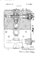
FIG. I is a horizontal cross-sectional view of a balltype embodiment of the valve;
FIG. 2 is a vertical sectional view taken substantially alone line 22 of FIG. 1;
FIG. 3 is an exploded isometric view of the valve ball, retainer/stop and operator of the valve embodiment of FIG. I;
FIG. 4 is a horizontal cross-sectional view of a gatetype embodiment of the valve;
FIG. 5 is an isometric view of the gate of the FIG. 4 embodiment; and
FIG. 6 is a vertical sectional view taken substantially along line 6-6 of FIG. 4.
DESCRIPTION OF THE PREFERRED EMBODIMENTS In FIGS. I and 2, the element 10 is a tubing bonnet or a lower portion thereof. In the instance where the II] is the bonnet, it is designed to be mounted upon the tubing head (bolted-type flange connections are illustrated; Grayloc clamp connections could be provided instead, as could other clamp-type connections). Normally, a master valve of the christmas tree would mount upon the tubing head, although in some instances the master valve housing could be cast integrally with the tubing bonnet. The upper ends of the tubing hangers (not depicted) extend into and seal with the tapered lower ends 12 of the longitudinal throughbores 14 of the tubing bonnet. (A dual, side-by-side completion is depicted.) The valve of the invention is equally applicable to single and multiple completions. An example of the location of a tubing head bonnet in a well head is shown on page 2245 of the l970-7l Edition of the Composite Catalog of Oilfield Equipment and Services, Gulf Publishing Company, Houston, Texas. The upper ends of the bores I4 are also tapered, by preference, to receive double tapered sealing cones which also seal with correspondingly oppositely tapered bores in the lower ends of the corresponding bores of the master valve (see pages 2242, 2245, 2247 and 2251 of the aforementioned Composite Catalog).
Intermediate its longitudinal extent, the bore 14 necks down and is provided with a downwardly facing, concave, spherically curved, annular valve seat I6 which may be integrally formed, or provided on a replaceable element. A valve ball 18 is shown disposed within the bore 14 against the seat 16. A retainer and stop element 20 supports the ball for 90 degree rotation between the open condition depicted in FIG. 2 and a closed condition wherein the diametric passageway 22 through the ball is completely out of registry with the bore 14. The retainer and stop element 20 is shown held in place in the bore 14 by a snap ring 24 which is accepted in a circumferential notch 26 in the bore 14.
The element 30 includes an annular body 32 having an upwardly facing, concave, spherically curved annular valve seat 34 machined into the radially inner corner of the upper end surface thereof. An arm 36 projects axially upwardly from one point on the radially outer corner of the upper end surface of the retainer body 32. The arm 36, near its upper extent is provided with a horizontally opening socket 38 of circular section.
it should now be noticed that the valve ball 18 has a portion of the spherically curved exterior surface thereof machined away to provide a trunnion or axle 40 centrally of a generally triangular recess 42 which runs out on one side at 44 and includes as its two other sides shoulders 46 and 48 disposed at right angles to one another and lying in planes parallel to the longitudinal axis of the trunnion 40. The latter is disposed midway between the intersections of the ball passageway 22, on a radian of the ball.
The trunnion 40 is received in the socket 38 to journal rotation of the ball while the spherical exterior of the ball is engaged between the seats 16 and 34. If necessary, one or both of the seats may be spring biased to increase their seating pressure against the ball and either surface 16 or 34 may be provided with a resilient annular sealing member disposed in an annular groove therein.
Diametrically opposite the trunnion 40, the valve ball is shown provided with a socket 50 of non-circular cross-sectional shape, a hexagonal socket being de picted.
Generally intermediate the seats 16 and 34, the passageway 14 is intersected by a grease chamber 52 for supplying lubricating grease to the exterior of the valve ball.
With reference to FIG. 1, the right-most of the two valves is shown in detail and the left one, which is a mirror image duplicate thereof, is suggested in more general outline. The valves are oriented so that the two trunnions 40 lie laterally adjacent one another in axial alignment, while the hexagonal sockets 50 thereof face outwardly of the outer sides of the valve balls.
Discussing now the right-most valve shown in most detail, the tubing head safety valve housing is further provided with a horizontal bore 54 in longitudinal alignment with the hexagonal socket 50.
Beginning at the intersection, the bore 54 which is at first generally cylindrical, becomes enlarged frustoconically at 56, is then threaded in another cylindrical segment at $8, is cylindrically enlarged again at 60, then frustoconically again at 62 and finally in another threaded cylindrical segment 64 which intersects the exterior of the housing 10.
A pinion 66 is provided with teeth 68 its outer periphery and is fixed on a shaft 70 intermediate the ends of the shaft. The inner end of the shaft is provided with a shaped portion 72 of a non-circular cross-sectional shape which is complementary with that of the socket 50. The portion 72 is received in the socket 50 so that rotation of the shaft causes coordinate rotation of the valve ball.
The shaft 70 is journaled for rotation in the bore 54 at 74 and 76 with the pinion positioned radially adjacent the bore portion 60.
A packing nut 78 is shown having a frustoconically tapered forward portion 80 provided with a circumferential, radially outwardly opening recess in which a sealing ring 82 is received. Behind its tapered portion 80, the nut 78 is exteriorly threaded at 84. The rear of the nut is provided with wrenching tabs 86 so the nut may be threaded into the bore at 58,84 so as to have its portion 80 in engagement with the bore portion 56 and sealed therewith at 82.
Within the through-bore 88 of the nut there is provided an axially extensive, radially inwardly opening, circumferential groove 90 which receives chevron packing 92 or its equivalent, for sealing with the exterior of the shaft 70 journaled there.
A bearing plug 94 is shown having a frustoconically tapered forward portion 96 provided with a circumferential, radially outwardly opening recess in which a sealing ring 98 is received. Behind its tapered portion 96, the plug 94 is exteriorly threaded at 100. The rear of the plug is provided with a non-circular wrenching socket 102 so the plug may be threaded into the bore 54 at 64,100 so as to have its portion 96 in engagement with the bore portion 62 and sealed therewith at 98.
The inner end of the plug 94 is provided with a longitudinally extending, radially inwardly opening socket 104 which receives the outer end of the shaft 70. Near its mouth, the socket 104 is radially enlarged to provide a circumferential recess 106 that receives an annular bearing element 108, e.g. made of lubricious plastic material for rotatively supporting the shaft with respect to the plug 94.
Notice now that the bore 54 is intersected at right angles intermediate its longitudinal extent, and specifically within its portion 60 by a horizontal bore 110. As is apparent from the figures, the longitudinal axis of the bore 110 lies above the longitudinal axis of the bore 54.
At its inner end, the bore 110 intersects the grease chamber 52 to become a continuation thereof. (A plug H2 closes off the outer end of the direct line 52.) From intersection with the grease chamber, the bore 110 continues, generally cylindrically, to intersection with the bore 54. as aforesaid, then on to a first cylindrical enlargement at 114, a frustoconical enlargement at 116, a cylindrical, internally threaded portion at 118, another enlargement producing an outwardly facing annular shoulder at [20 and finally to another cylindrical, internally threaded portion at 122.
The portion 114 is intersected by a bore 124 generally parallel to the bore 54 which is provided with a grease fitting at [26 to constitute a grease injection port for replenishing grease within the system and for providing grease to the grease chamber 52 for lubricating the valve ball. Periodically, grease may be forced in through the grease fitting under sufficient pressure to displace substantially all of the old grease within the system to purge contaminated grease.
A breather port 128 communicates between the exterior of the housing and the bore 110 adjacent the shoulder 120.
The bore 110 receives a shaft 130 whose inner end is slotted at 132 to pass grease and to communicate pressure. A short distance back from the inner end begins a long exteriorly threaded portion I34 whose threads I36 are configured to mesh with the teeth of the pinion gear 66. At the outer end of the threaded portion, the shaft 130 is radially enlarged to provide a circumferentially extending band 138 having an outwardly facing frustoconically curved sealing surface I40 which constitutes the outer end surface of the band 138. From there, the shaft 130 is generally cylindrical and smooth in the region 142 proceeding to its outer end 144 which mounts a piston 146. The shaft end portion 144 is shown being exteriorly threaded to mount the piston via a complementary internally threaded socket 148 in the back face of the piston, but alternative mounting arrangements could have been provided.
The piston 146 is generally disk-shaped with a circumferentially extending, radially outwardly opening, O-ring receiving groove 150 in the radially outer peripheral surface thereof. The groove 150 receives an O-ring seal assembly 152.
The inner end of the shaft 130 as shown is of sufficiently great diameter to be self-journaled in the bore 110 for longitudinal sliding (and rotation under certain circumstances) therein.
The outer end region 142 is journaled and sealed with respect to the bore by a packing nut 154 which is substantially identical in design to the packing nut 78. That is, it has a frustoconically tapered forward portion 156 provided with a circumferential, radially outwardly opening recess in which a sealing ring 158 is received. Behind its tapered portion 156, the nut 154 is exteriorly threaded at 160. The rear of the nut is provided with wrenching tabs 162 so the nut may be threaded into the bore at 118,160 so as to have its portion 156 in engagement with the bore portion 116 and sealed therewith at I58.
Within the through-bore 164 of the nut 154 there is provided an axially extensive, radially inwardly opening, circumferentially extending groove 166 which receives chevron packing 168 or its equivalent, for sealing with the shaft portion 142 journaled there.
The inner end of the nut I54, radially adjacent the emergence of the through-bore 164 is provided with a frustoconical recess forming a seat 170 complementary to the sealing surface 140 on the shaft 130 band 138.
As will be more fully appreciated after this entire description has been read, when the ball valve is fully closed, the seal I40 engages the seat 170, metal on metal, to provide for positive sealing in an instance where high temperatures from a fire may have damaged the chevron packing.
The piston 146 is housed within a cup-shaped cylinder member I72 which threads into the outer end portion I22 of the bore 110 at 174. The member 172 has a cylindrical inner sidewall 176 which is sealingly engaged by the O-ring 152.
Pressure is admitted to the cylinder 172 through the exterior line 177 for forcing the piston inwardly to open the valve. When the piston is forced in, the shaft 130 moves longitudinally inwardly causing rotation of the pinion 66. That, in turn, rotates the shaft which rotates the valve ball a maximum of degrees between a closed condition and an open condition. Stops to further rotation are effected by abutment of the ball shoulder 46 or 48 with an end surface of the ball carrier 30 arm 36.
In axial alignment with the piston shaft 130, the cylinder member end is provided with an opening 178 and the outer end of the piston is provided with an indicator/manual actuator 180 which protrudes toward visibility and accessibility through the opening 178. Visibility of the member 180 through the opening 178 indicates that the valve is in a closed condition. A coil spring 182 is preferably installed between the back of the piston and the packing nut 154 to ensure return of the valve to a closed condition upon release of external pressure.
As a review, it is emphasized that, if well pressure exceeds the design pressure of the valve, that excessive pressure, transmitted through the grease chamber 52 will act upon the piston shaft, forcing it outwardly, adcling to the restoring force of the spring 182, overcoming the force on the piston from the external pressure source 177 thus closing the valve. The external pressure line 177 may then be shut off to prevent intermittent opening and closing of the valve due to reversing pressure imbalances.
The valve may be manually operated by pulling, pushing or turning the indicator/manual actuator 180.
The breather port 128 allows air to be exhausted from behind the piston during opening of the valve and for admission of air to the expanding space behind the piston during closing of the valve in order to avoid interfering with smooth sliding of the piston.
In FIGS. 4 and 6 the element 210 is a tubing bonnet or a lower portion thereof, as described in relation to element 10 of FIGS. 1 and 2. The upper ends oftubing hangers (not depicted) extend into and seal with the tapered lower ends 212 of the two longitudinal throughbores 214 of the tubing bonnet. (A dual, sideby-side completion is depicted.) The principles of the valve of FIGS. 4-6 are equally applicable to single and multiple completions.
Intermediate its longitudinal extent, each bore 214, above the tapered seats 212, includes a circumferential seat 216 for receipt ofa snap ring retainer 218, a cylindrically curved portion 220 (intersected laterally intermediate its longitudinal extent by a gate chamber 222), a frustoconically tapered portion 224, an annular seat 226 which faces the gate chamber 222, an axially short cylindrically curved portion 226 and a frustoconically flaring portion 228 leading to the upper end of the bonnet 210.
Above the gate chamber 220, each bore 214 receives an annular valve seat member 230 in the form of a tu bular element having a right, flat lower end surface 232 adapted and positioned to seat against the valve gate 234 (to be further described below) and an upper exteriorly tapered end region 236,238 adapted to seat and seal with the portions 226,224. (A circumferential groove 240 in the region 238 receives a resilient seal ring 242 as an initial seal for the metal-on-metal seal established at 238,224).
The snap ring retainer 218 supports an annular spacer 244 that serves as a support for a stack of spring washers 246. The spring washers resiliently bias a tubular driver sleeve 248 which they support, into contact with the underside of the valve gate 234. The upper end 250 of the driver sleeve 248 is generally cylindrically curved so it is upwardly concave.
Each gate chamber 222 is generally cylindrical in transverse cross-sectional shape, the bore 253 which forms it communicates through the bonnet at one end 254.
The gate itself 234 is a part-cylindrical element constituting sufficiently angularly more than half a right circular cylinder that the gate is securely, longitudinally slidably received in the gate chamber 222. Oriented as depicted, the gate 234 has a rounded lower side 256 in sliding contact with the driver sleeve upper end surface 250 and a flat upper side in sliding contact with the flat lower end surface 232 of the valve seat member 230.
The members and portions 244, 246, 248, 230 and 226 have substantially equal internal diameters to provide a generally cylindrical passageway 258.
The gate 234 (FIGS. and 6 orientation) has a port 260 vertically through it nearer its right end. The port 260 has a diameter substantially matching that of the members 244, 246, 248, 230 and 226 so that when each valve is open its longitudinal passageway is unobstructed.
The gate 234 is blind" to the left of the port 258, except that it may be provided with e.g. a ball check valve 262 so oriented that when the gate is closed, i.e. moved rightwardly, so that the port 260 is out of registry with the passageway 258 and the check valve 262 is in registry with the passageway 258, fluid may be pumped down into the well which has been provided with the bonnet 210. In order to open the check valve 262 it is necessary to pressurize the fluid to be admitted to a degree sufficient to overcome the pressure from below tending to seat the ball-check 264 of the check valve, and the spring force upwardly incumbent upon the ballcheck 264 due to the spring 266.
A strong coil spring 270 is received in the gate chamber bore 253 ahead of the gate 234. The spring 270- abuts the inner end 272 of the bore 253 and the inner end 274 of the gate 234, urging the gate toward a gate-closed condition. Absent an overwhelming force intentionally exerted on the gate to urge it leftwards, the spring 270 will force the gate 234 to a gate-closed condition.
At its right end, each gate 234 has a stem socket 278 which receives a valve stem 280 which may be moved longitudinally to open and close the gate.
Intermediate its outer end 254 and its intersection with the bore 214, the gate chamber bore 253 tapers frustoconically to provide an annular seating surface 282 which faces radially inwardly and toward the bore end 254.
Between the tapered seating surface 282 and the bore end 254, the bore 253 has a first threaded portion 284, an unthreaded circumferentially grooved portion 286 and a second threaded portion 284.
A breather port 288 is provided in the element 210, communicating the grooved portion 286 of the bore 253 with the atmosphere exteriorly of the element 210.
The valve stem 280 is provided with two axially spaced circumferential ridges 290,292 at its inner end. The inner ridge 290 fits in the stern socket 278 to connect the stem to the gate. The outer ridge 292 lies just outside the stern socket and has an axially outwardly facing frustoconically curved annular seat surface 294 thereon.
A tapered annular plug 296 is received in the bore 253 with a tapered annular outer peripheral surface 298 thereof in metal surface-to-surface engagement with the tapered bore surface 282.
The plug 296, adjacent and surrounding the inner end of its throughbore 300 is provided with a frustoconically curved annular seat 302 which complements and is arranged to be engaged by and seal in metal surface-to-surface sealing contact with the annular seat surface 294 on the valve stem.
Adjacent and recessed into the outer end of the bore of the plug 296, there is provided an annular socket 304 which receives a quantity of chevron packing 306.
A gland nut 308, threadably received in the bore 253 at 284, bears on and compresses the outer end of the annulus of packing 306, stops at 310 against a shoulder 312 on the back of the plug 292 to prevent over-compression of the packing and includes axially outwardly opening socket means whereby the plug may be engaged by a tool for threading the plug home and for removing the plug. The chevron packing seals between the plug 296 and the valve stem when the valve is partly or fully open. When the valve is fully closed, the chevron packing assumes a role secondary to the seal accomplished at 294,302.
There is further provided a cup-shaped cylinder member 314 which includes a tubular sidewall 316 and an outer end wall 318. The sidewalls 316 is exteriorly threaded at 318' near its end opposite from its end wall end to permit threaded receipt of the cylinder member 314 at 284, capping the outer end of the bore 253.
The sidewall 316 may be threaded into the bore 253 until its inner end 320' abuts the outer end of the gland nut 308. Radially inwardly adjacent the groove 286, the sidewall 316 is provided with a plurality of ports 318' for communicating the inner end of the cylinder chamber 320 with the breather port 288 via the groove 286.
Within the cylinder chamber 320 a piston 322 is slidably received for axial movement. The piston 322 is shown being generally circular disk-shaped and having an outwardly opening circumferential groove 324 in its outer peripheral surface, for receipt of an O-ring seal member 326. The latter seals with the inner cylindrically curved sidewall surface 328 of the cylinder sidewall.
The outer end of the valve stem 280 is exteriorly threaded at 330 to accommodate threaded securement thereof in an internally threaded socket 332 in the, inner end of the piston 322. A smaller internally threaded socket 334 in the outer end of the piston receives the inner exteriorly threaded end 336 of a combined visual indicator/manual actuator rod 338 whose outer end projects axially outwardly of the cylinder chamber through the end wall 318. The end wall 318 is provided with an internally threaded opening 340 which threadably receives an exteriorly threaded annular nut having a resilient annular seal ring 342 fitted in a radially inwardly opening circumferential recess 344 in its bore 346. The indicatorlactuator passes out through the bore 346 in sealing contact with the ring 342.
Pressure for urging the piston 322 to its inner position as depicted in FIG. 6 is admitted to the cylinder chamber at the outer corner thereof via a control pressure port 348. It is this pressure which is supplied to overcome the restoration force of the spring 270 and to thus maintain the valve in an open condition.
When the valve is in a full open condition a tapered metal-to-metal seal is established between the inner end of the piston and the outer end of the packing gland nut at 349,351.
When the force due to pressure within the well in cumbent on the valve of FIGS. 4-6 exceeds the force applied via external pressure on the piston, minus the force due from compression of the return spring, the valve gate is urged rightwardly to a closed condition due to the surface area imbalance on the valve stem exposed to well pressure.
ln the discussion relating to the embodiment of H68. 4-6 only one of the two identical valves has been elaborated upon; the other could be discussed with the same details.
lt should be apparent that when using the gate valve embodiment, as when using the ball valve embodiment, of the safety valve of the invention, the valve is failclosed, is held open by the application of differential pressure to a fluid piston which functions as the actuator for the valve stem, has means which provide for manual push/pull actuation in the event of an unlikely failure condition, which externally indicates the position of the gate and which provides metal-to-metal seals for positive assurance that fire damage to a packing-type seal will not cause the safety valve to fail.
It should now be apparent that the petroleum well safety valve as described hereinabove possesses each of the attributes set forth in the specification under the heading Summary of the Invention" hereinbefore. Because the petroleum well safety valve of the invention can be modified to some extent without departing from the principles of the invention as they have been outlined and explained in this specification, the present invention should be understood as encompassing all such modifications as are within the spirit and scope of the following claims.
What is claimed is:
l. A safety valve for incorporation in the flow path of petroleum issuing from a petroleum well, comprising:
a tubular housing forming a part of a petroleum well completion, said tubular housing having means defining a vertical throughbore through which petroleum issues from the well when said safety valve is in an open condition;
a valve body movably interposed in said throughbore; means supporting said valve body in said throughbore for movement between a first position wherein said valve body completely obstructs the throughbore, providing a closed condition of the valve and a second position wherein said throughbore is substantially free of obstruction by said valve body, providing an open condition of the valve;
actuator means for moving said valve body between said two conditions thereof, the actuator means including: a piston slidably received in means defining a cylinder chamber;
means connecting one side of said piston to said valve body so that as said piston slides between two opposite extremes in said chamber said valve body is moved between the two conditions thereof;
outside source means communicating fluid pres sure to said chamber on one side of said piston in the sense to urge the piston toward the extreme wherein said valve body is in an open condition;
driving surface means on said piston connecting means presented in an opposing sense to said one side of said piston;
fluid tight means enclosing said driving surface means and communicating with the throughbore of said tubular housing so that the petroleum issuing from said well via said throughbore tends to urge the piston toward the extreme wherein said valve is in a closed condition,
so that, when the longitudinal force component due to the well pressure incumbent upon the piston connecting means exceeds the longitudinal force component due to the outside source means pressure incumbent upon the piston by a predetermined amount, the valve body will move to the closed condition thereof.
2. The safety valve of claim I further comprising resilient means engaging at least one of said piston connecting means and said piston and biasing said piston toward the extreme thereof corresponding to the closed condition of the valve body for enhancing the fail-safety of the valve.
3. The safety valve of claim 1 wherein the tubular housing comprises a portion of a tubing bonnet for a plural, side-by-side completion and said throughbore constitutes one of a plurality of such throughbores in said tubing bonnet.
4. The safety valve of claim 1 wherein the valve body is a valve gate mounted for reciprocation between the two conditions thereof.
5. The safety valve of claim 4 wherein said gate includes a port which is axially aligned with said throughbore when said valve body is in the open condition thereof and a blind portion which completely obstructs the throughbore when said valve body is in the closed condition thereof; the blind portion of the valve gate including means defining a one-way check valve therein, communicating the upper side thereof with the lower side thereof in such unidirectional sense as to permit fluids to be pumped down through the throughbore and into the well while prohibiting escape of fluids from the well via said throughbore.
6. The safety valve of claim 4 wherein the piston connecting means comprises a valve stem and said fluid tight means comprises an annulus of packing material slidingly sealing with said valve stem between said piston and said driving surface means.
7. The safety valve of claim 6 wherein said tubular housing further includes a lateral bore entering at one side thereof and intersecting said throughbore intermediate the vertical extent of said throughbore and having an inner end within said tubular housing;
said valve gate being received in said lateral bore for sliding movement longitudinally of said valve gate and said lateral bore; and
resilient spring means received in the segment of the lateral bore defined between said throughbore and said inner end, said spring means engaging said valve gate and said inner end and biasing the gate toward the closed condition thereof.
8. The safety valve of claim 7 wherein said gate includes cradle means on the opposite end thereof from said spring means; said valve stem having an enlarged portion adjacent the inner end thereof, said enlarged portion being received in said cradle means for connecting the valve stem to the valve gate and for disposing said driving surface means, at the inner end of said valve stem, within the lateral bore.
9. The safety valve of claim 8 further comprising visual indicator/manual actuator means secured coaxially on the opposite side of the piston'from the valve stem and protruding from the cylinder chamber through means defining an annular seal in the outer end of said cylinder chamber.
10. The safety valve of claim 7 wherein the annulus of packing is maintained between two annular members received in said lateral bore, said annular members being configured and mounted for movement axially toward one another to compress said packing into sealing engagement with said valve stem; and
means defining complementarily configured annular metal seal means on said piston and the outer of said annular packing maintaining members engageable in surface-to-surface sealing relationship when said valve body is in an open condition.
ll. The safety valve of claim 10 further including:
means defining complementarily configured radially outwardly extruding annular metal seal means on said valve stem adjacent the inner end thereof and the inner of said annular packing maintaining members engageable in surface-to-surface sealing relationship when said valve body is in a closed condition.
12. The safety valve of claim 7 wherein said cylinder chamber is constituted by a cup-shaped member secured at the outer end of said lateral bore.
13. The safety valve of claim 1 wherein the valve body is a valve ball mounted for rotation between the two conditions thereof.
14. The safety valve of claim 13 further including:
an integral ball retainer and stop element comprising a tubular seat portion having an axially projecting arm at one end thereof;
means defining an opening radially through said axially extending arm;
means defining a throughbore through said valve ball;
means defining a notch in the exterior of said valve ball between the opposite end intersections of the valve ball throughbore with the exterior of the valve ball;
means defining a trunnion within said recess, extending along a radius of said valve ball, said recess having two sidewall portions defining opposite extents of said recess, said two sidewall portions being disposed at right angles to one another and both paralleling the longitudinal axis of said trunnion;
the trunnion being rotatably received in said opening in said arm with said valve ball seated on said end of said tubular seat portion;
said sidewall portions being positioned to alternately engage opposite sides of said arm when said valve ball is in the two opposite conditions thereof to limit rotation of said ball to rotation between said two conditions thereof.
15. The safety valve of claim 13 further comprising:
means defining a throughbore through the valve ball;
axle means extending from diametrically opposite sides of said valve ball midway between the intersections of the ends of said valve ball throughbore with the exterior of the valve ball;
one of said axle means extending axially in means defining a first lateral passageway extending outwardly in said tubular housing from an intersection with the throughbore of the tubular housing at said valve ball;
first and second annular bearing means in said first lateral passageway respectively proximally and distally of said valve ball;
said annular bearing means journalling said one axle means between them;
a pinion fixed on said one axle means between the first and second annular bearing means;
a second lateral passageway intersecting the first lateral passageway at generally right angles thereto at the location of said pinion;
means defining a cylinder chamber at one outer extent of the second lateral passageway;
a piston slidably received in the cylinder chamber in sealing engagement with the interior thereof;
piston shaft means secured to the inner side of said piston and extending in said second lateral passageway past said pinion;
journalling means at the inner end of said piston shaft journalling the piston shaft inner end with respect to the second lateral passageway for axial sliding movement therein;
means defining a rack gear on said piston shaft with teeth thereon engageable with said pinion, whereby rotation of the valve ball results in a corresponding axial movement of said piston shaft and said piston and whereby axial movement of said piston results in a corresponding rotation of said valve ball;
annular packing means in said second lateral bore sealingly engaging said bore and said piston shaft to seal the piston receiving cylinder chamber from the second lateral bore inwardly of the annular packing means;
passage means communicating the throughbore of said tubular housing at the valve ball with the second lateral passageway axially inwardly beyond the inner end of the piston shaft; and
means for communicating an external source of fluid pressure to within the cylinder chamber against the opposite side of said piston from said piston shaft, whereby an external source of pressure may be applied to the piston, driving it axially inwardly, thus rotating the first axle means in a first sense to rotate the valve ball to an open condition and whereby excessive pressure within the tubular housing throughbore, acting through said passage means will drive said piston shaft axially outwardly, thus rotating the first axle means in a second, opposite sense to rotate the valve ball to a closed condition.
16. The safety valve of Claim further including conduit means extending from externally of the tubular housing into communication with the second lateral bore inwardly of said annular packing; and means for introducing grease under pressure through said conduit means for lubricating said valve ball.
17. The safety valve of claim 16 further including interengageable annular metal seal members on said piston shaft outwardly from said rack and in said second lateral bore behind said piston, engaged when the valve ball is in a closed condition to obviate reliance on said packing for primary sealing when said valve ball is closed.
18. A built-in operator valve for incorporation in a flow path comprising:
a tubular housing, said tubular housing having means defining a vertical throughbore through which fluid may flow when said safety valve is in an open condition; a valve body movably interposed in said throughbore; means supporting said valve body in said throughbore for movement between a first position wherein said valve body completely obstructs the throughbore, providing a closed condition of the valve and a second position wherein said throughbore is substantially free of obstruction by said valve body, providing an open condition of the valve;
actuator means for moving said valve body between said two conditions thereof, the actuator means including:
a piston slidably received in means defining a cylinder chamber;
means connecting one side of said piston to said valve body so that as said piston slides between two opposite extremes in said chamber said valve body is moved between the two conditions thereof;
outside source means communicating fluid pressure to said chamber on one side of said piston in the sense to urge the piston toward the extreme wherein said valve body is in an open condition;
driving surface means on said piston connecting means presented in an opposing sense to said one side of said piston;
fluid tight means enclosing said driving surface means and communicating with the throughbore of said tubular housing so that the fluid flowing through said throughbore tends to urge the piston toward the extreme wherein said valve is in a closed condition,
so that, when the longitudinal force component due to fluid pressure incumbent upon the piston connecting means exceeds the longitudinal force component due to the outside source means pressure incumbent upon the piston by a predetermined amount, the valve body will move to the closed condition thereof.
19. The safety valve of claim 18 further comprising resilient means engaging at least one of said piston connecting means and said piston and biasing said piston toward the extreme thereof corresponding to the closed condition of the valve body for enhancing the fail-safety of the valve.
20. The safety valve of claim 18 wherein the tubular housing comprises a portion of a block for a multiplicity of like side-by-side safety valves and said throughbore constitutes one of a plurality of such throughbores in said block.
21. The safety valve of claim 18 wherein the valve body is a valve gate mounted for reciprocation between the two conditions thereof.
22. The safety valve of claim 21 wherein said gate in cludes a port which is axially aligned with said throughbore when said valve body is in the open condition thereof and a blind portion which completely obstructs the throughbore when said valve body is in the closed condition thereof; the blind portion of the valve gate including means defining a one-way check valve therein, communicating the upper side thereof with the lower side thereof in such unidirectional sense as to permit fluids to be pumped through the throughbore and beyond the safety valve in one direction while prohibiting escape of fluids via said throughbore in the opposite direction.
23. The safety valve of claim 20 wherein the piston connecting means comprises a valve stem and said fluid tight means comprises an annulus of packing material slidingly sealing with said valve stem between said piston and said driving surface means.
24. The safety valve of claim 23 wherein said tubular housing further includes a lateral bore entering at one side thereof and intersecting said throughbore intermediate the vertical extent of said throughbore and having an inner end within said tubular housing;
said valve gate being received in said lateral bore for sliding movement longitudinally of said valve gate and said lateral bore; and
resilient spring means received in the segment of the lateral bore defined between said throughbore and said inner end, said spring means engaging said valve gate and said inner end and biasing the gate toward the closed condition thereof.
25. The safety valve of claim 24 wherein said gate includes cradle means on the opposite end thereof from said spring means; said valve stem having an enlarged portion adjacent the inner end thereof, said enlarged portion being received in said cradle means for connecting the valve stem to the valve gate and for disposing said driving surface means, at the inner end of said valve stem, within the lateral bore.
26. The safety valve of claim 25 further comprising visual indicator/manual actuator means secured coaxially on the opposite side of the piston from the valve stem and protruding from the cylinder chamber through means defining an annular seal in the outer end of said cylinder chamber.
27. The safety valve of claim 24 wherein the annulus of packing is maintained between two annular members received in said lateral bore, said annular members being configured and mounted for movement axially toward one another to compress said packing into sealing engagement with said valve stem; and
means defining complementarily configured annular metal seal means on said piston and the outer of said annular packing maintaining members engageable in surface-to-surface sealing relationship when said valve body is in an open condition.
28. The safety valve of claim 27 further including:
means defining complementarily configured radially outwardly extruding annular metal seal means on said valve stem adjacent the inner end thereof and the inner of said annular packing maintaining members engageable in surface-to-surface sealing relationship when said valve body is in a closed condition.
29. The safety valve of claim 24 wherein said cylinder chamber is constituted by a cup-shaped member secured at the outer end of said lateral bore.
30. The safety valve of claim 18 wherein the valve body is a valve ball mounted for rotation between the two conditions thereof.
31. The safety valve of claim 30 further including:
an integral ball retainer and stop element comprising a tubular seat portion having an axially projecting arm at one end thereof;
means defining an opening radially through said axially extending arm;
means defining a throughbore through said valve ball;
means defining a notch in the exterior of said valve ball between the opposite end intersections of the valve ball throughbore with the exterior of the valve ball;
means defining a trunnion within said recess, extending along a radius of said valve ball, said recess having two sidewall portions defining opposite extends of said recess, said two sidewall portions being disposed at right angles to one another and both paralleling the longitudinal axis of said trunnion;
the trunnion being rotatably received in said opening in said arm with said valve ball seated on said end of said tubular seat portion;
said sidewall portions being positioned to alternately engage opposite sides of said arm when said ball is in the two opposite conditions thereof to limit rotation of said ball to rotation between said two conditions thereof.
32. The safety valve of claim 30 further comprising:
means defining a throughbore through the valve ball;
axle means extending from diametrically opposite sides of said valve ball midway between the intersections of the ends of said valve ball throughbore with the exterior of the valve ball;
one of said axle means extending axially in means defining a first lateral passageway extending outwardly in said tubular housing from an intersection with the throughbore of the tubular housing at said valve ball;
first and second annular bearing means in said first lateral passageway respectively proximally and distally of said valve ball;
said annular bearing means journalling said one axle means between them;
a pinion fixed on said one axle means between the first and second annular bearing means;
a second lateral passageway intersecting the first lateral passageway at generally right angles thereto at the location of said pinion;
means defining a cylinder chamber at one outer extent of the second lateral passageway;
a piston slidably received in the cylinder chamber in sealin engagement with the interior thereof; I piston s aft means secured to the inner slde of said piston and extending in said second lateral passageway past said pinion;
journalling means at the inner end of said piston shaft journalling the piston shaft inner end with respect to the second lateral passageway for axial sliding movement therein;
means defining a rack gear on said piston shaft with teeth thereon engageable with said pinion. whereby rotation of the valve ball results in a corresponding axial movement of said piston shaft and said piston and whereby axial movement of said piston results in a corresponding rotation of said valve ball;
annular packing means in said second lateral bore sealingly engaging said bore and said piston shaft to seal the piston receiving cylinder chamber from the second lateral bore inwardly of the annular packing means;
passage means communicating the throughbore of said tubular housing at the valve ball with the second lateral passageway axially inwardly beyond the inner end of the piston shaft; and
means for communicating an external source of fluid pressure to within the cylinder chamber against the opposite side of said piston from said piston shaft, whereby an external source of pressure may be applied to the piston, driving it axially inwardly, thus rotating the first axle means in a first sense to rotate the valve ball to an open condition and whereby excessive pressure within the tubular housing throughbore, acting through said passage means will drive said piston shaft axially outwardly, thus rotating the first axle means in a second. opposite sense to rotate the valve ball to a closed condition.
33. The safety valve of claim 32 further including conduit means extending from externally of the tubular housing into communication with the second lateral bore inwardly of said annular packing; and means for introducing grease under pressure through said conduit means for lubricating said valve ball.
34. The safety valve of claim 33 further including interengageable annular metal seal members on said piston shaft outwardly from said rack and in said second lateral bore behind said piston, engaged when the valve ball is in a closed condition to obviate reliance on said packing for primary sealing when said valve ball is closed.