US3708631A - Quadraphonic reproducing system with gain control - Google Patents
Quadraphonic reproducing system with gain control Download PDFInfo
- Publication number
- US3708631A US3708631A US00044196A US3708631DA US3708631A US 3708631 A US3708631 A US 3708631A US 00044196 A US00044196 A US 00044196A US 3708631D A US3708631D A US 3708631DA US 3708631 A US3708631 A US 3708631A
- Authority
- US
- United States
- Prior art keywords
- signals
- signal
- control
- channels
- composite
- Prior art date
- Legal status (The legal status is an assumption and is not a legal conclusion. Google has not performed a legal analysis and makes no representation as to the accuracy of the status listed.)
- Expired - Lifetime
Links
- 239000002131 composite material Substances 0.000 claims abstract description 65
- 238000000034 method Methods 0.000 claims abstract description 12
- 230000008878 coupling Effects 0.000 claims description 24
- 238000010168 coupling process Methods 0.000 claims description 24
- 238000005859 coupling reaction Methods 0.000 claims description 24
- 230000004044 response Effects 0.000 claims description 16
- 238000012546 transfer Methods 0.000 claims description 12
- 230000005540 biological transmission Effects 0.000 claims description 11
- 238000007493 shaping process Methods 0.000 claims description 7
- 238000000926 separation method Methods 0.000 claims description 4
- 230000008054 signal transmission Effects 0.000 claims description 2
- 230000033001 locomotion Effects 0.000 description 15
- 238000010586 diagram Methods 0.000 description 10
- 230000009471 action Effects 0.000 description 7
- 241001422033 Thestylus Species 0.000 description 6
- 230000000694 effects Effects 0.000 description 6
- 230000006870 function Effects 0.000 description 5
- 101000860173 Myxococcus xanthus C-factor Proteins 0.000 description 4
- 230000003321 amplification Effects 0.000 description 3
- 238000004458 analytical method Methods 0.000 description 3
- 210000005069 ears Anatomy 0.000 description 3
- 238000003199 nucleic acid amplification method Methods 0.000 description 3
- 230000010363 phase shift Effects 0.000 description 3
- 239000000654 additive Substances 0.000 description 2
- 230000000996 additive effect Effects 0.000 description 2
- 230000002238 attenuated effect Effects 0.000 description 2
- 239000003990 capacitor Substances 0.000 description 2
- 238000002474 experimental method Methods 0.000 description 2
- 239000011159 matrix material Substances 0.000 description 2
- 238000011160 research Methods 0.000 description 2
- 208000019300 CLIPPERS Diseases 0.000 description 1
- 235000013405 beer Nutrition 0.000 description 1
- ZYXYTGQFPZEUFX-UHFFFAOYSA-N benzpyrimoxan Chemical compound O1C(OCCC1)C=1C(=NC=NC=1)OCC1=CC=C(C=C1)C(F)(F)F ZYXYTGQFPZEUFX-UHFFFAOYSA-N 0.000 description 1
- 230000015572 biosynthetic process Effects 0.000 description 1
- DSKJPMWIHSOYEA-UHFFFAOYSA-N bupirimate Chemical compound CCCCC1=C(C)N=C(NCC)N=C1OS(=O)(=O)N(C)C DSKJPMWIHSOYEA-UHFFFAOYSA-N 0.000 description 1
- 208000021930 chronic lymphocytic inflammation with pontine perivascular enhancement responsive to steroids Diseases 0.000 description 1
- 239000004020 conductor Substances 0.000 description 1
- 230000003247 decreasing effect Effects 0.000 description 1
- 238000006073 displacement reaction Methods 0.000 description 1
- 230000003993 interaction Effects 0.000 description 1
- 239000004922 lacquer Substances 0.000 description 1
- 238000005259 measurement Methods 0.000 description 1
- 238000012986 modification Methods 0.000 description 1
- 230000004048 modification Effects 0.000 description 1
- 238000009527 percussion Methods 0.000 description 1
- 230000009467 reduction Effects 0.000 description 1
- 230000035807 sensation Effects 0.000 description 1
- 230000035945 sensitivity Effects 0.000 description 1
- 238000004088 simulation Methods 0.000 description 1
- 230000005236 sound signal Effects 0.000 description 1
- 238000012360 testing method Methods 0.000 description 1
- 238000013519 translation Methods 0.000 description 1
Images


Classifications
-
- H—ELECTRICITY
- H04—ELECTRIC COMMUNICATION TECHNIQUE
- H04S—STEREOPHONIC SYSTEMS
- H04S3/00—Systems employing more than two channels, e.g. quadraphonic
- H04S3/02—Systems employing more than two channels, e.g. quadraphonic of the matrix type, i.e. in which input signals are combined algebraically, e.g. after having been phase shifted with respect to each other
Definitions
- the two tracks may be provided by any one of several available two-track systems, such as two-track tape, the stereomultiplex system of broadcasting, or a stereophonic disc record, on which two of the four channels are applied as usual, with the third and fourth channels superimposed thereon by respectively applying equal portions of them in-phase and out-ofphase to the two tracks in accordance with known practice.
- two-track tape such as two-track tape, the stereomultiplex system of broadcasting, or a stereophonic disc record, on which two of the four channels are applied as usual, with the third and fourth channels superimposed thereon by respectively applying equal portions of them in-phase and out-ofphase to the two tracks in accordance with known practice.
- the reproducing apparatus includes transducer means for recovering the composite signals from the two tracks, circuit means for deriving the four channels by appropriately adding and subtracting components of the composite signals, four separate loudspeakers, and control circuitry which recognizes the channel or channels having the dominant signal and which controls the instantaneous amplitudes of signals delivered to the four loudspeakers in a manner to give a substantially perfect illusion of four separate independent sources of sound.
- the modern stereophonic phonograph is capable of recording, or encoding, modulation along two separate channels, which geometrically are at 90 to each other and at 45 to the disc surface. It is usual practice to include a third channel by matrixing or adding it as a phantom channel to the other two, which causes it to be recorded as lateral modulation parallel to the record surface. Oftentimes, to obtain special effects, some of the channels are applied to the tracks in phase opposition, in a manner exemplified by test records Models STR 110, Ill and 120 produced and distributed by CBS Laboratories, a Division of the Assignee of this invention.
- the third (or central) channel appears on the two loudspeakers of the stereophonic phonograph, and an observer placed centrally between the loudspeakers perceives the illusion of the third channel being located between the other two.
- the fourth, or vertical, channel when reproduced on a conventional two-loudspeaker stereophonic phonograph gives the illusion of spread" sound.
- a principal object of the present invention is to provide a method and apparatus for reproducing and separately presenting on independent loudspeakers four channels of information recorded as described above on an otherwise two-track record medium, such as a stereophonic disc record, a two-track tape system having separate recording and reproducing heads for each track, or the stereo-multiplex broadcasting system which provides for transmission of two independent channels, or tracks of information, such that the listener experiences the illusion of listening to a corresponding number of separate sources of sound.
- an otherwise two-track record medium such as a stereophonic disc record, a two-track tape system having separate recording and reproducing heads for each track, or the stereo-multiplex broadcasting system which provides for transmission of two independent channels, or tracks of information, such that the listener experiences the illusion of listening to a corresponding number of separate sources of sound.
- Another object of the invention is to provide a more realistic illusion of four separate channels than is afforded by the system described in the aforementioned copending application.
- the invention is applicable to any of the aforementioned presently available two-track systems of recording and/or transmission on which two of the four separate channels of information are applied in the usual manner, with the other two channels superimposed on the two tracks by applying equal portions of them in phase and relatively shifted in phase, respectively.
- two of the channels are recorded on the two separate tracks provided by the walls of the groove
- a third channel is recorded by applying equal portions of the signal in phase to the left" and right channels of the stereophonic cutter to produce lateral modulation of the groove
- the fourth channel is recorded by applying it in equal amounts, but displaced in phase, to the left and right" terminals of the cutter to produce vertical modulation of the record groove.
- the fourth signal may be applied through a phase-shift network which produces two signals displaced in phase from each other to cause the cutter stylus to execute an elliptical motion rather than the purely up and down motion produced by a difference signal.
- the information recorded or transmitted on the medium is reproduced by an appropriate transducer to produce two composite signals, a left" signal which contains, in addition to the left channel signal, a fraction of the third channel and a similar fraction of the fourth channel, and a right signal containing the right channel signal, a fraction of the third signal, and a similar fraction of the fourth signal, the latter, however, being in the negative sense.
- a left signal which contains, in addition to the left channel signal, a fraction of the third channel and a similar fraction of the fourth channel
- a right signal containing the right channel signal, a fraction of the third signal, and a similar fraction of the fourth signal, the latter, however, being in the negative sense.
- An important aspect of the playback apparatus of the invention is that the instantaneous amplitudes of the four independent signals delivered to four corresponding loudspeakers are automatically controlled in response to the signals then present on the four channels so as to give the listener a substantially perfect illusion of four separate independent sources of sound.
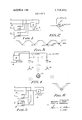
- FIG. 1 is a schematic diagram of a system for recording four channels of information on a stereophonic record
- FIG. 2 is a vector diagram useful in explaining the motion of the cutter stylus in response to application of left, right, center and difference signals;
- FIG. 3 is a cross sectional view of a fragmentary portion of a record showing four record grooves on a greatly enlarged scale, to illustrate the motion of the cutter in response to various signals;
- FIG. 4 is a schematic diagram of a prior art stereophonic playback system for providing the illusion of a third channel
- FIG. 5 is a schematic diagram of a system according to the invention for recording four channels on a twotrack stereophonic record
- FIG. 6 is a greatly enlarged illustration of a record groove illustrating the effect of applying the difference signal to the left and right channels through a phase shift network
- FIG. 7 is a schematic diagram of one form of playback apparatus embodying the invention.
- FIG.7A is a circuit diagram of a transmission network forming part of the system of FIG. 7;
- FIG. 8 is a curve showing the transfer characteristic of the logic circuitry of FIG. 7, useful in explaining the operation of the system;
- FIG. 9 is a block diagram of a preferred embodiment of the playback apparatus.
- FIG. 10 is a curve showing the transfer characteristics of the logic circuitry of FIG. 9.
- FIG. 1 1 is a block diagram of still another alternative embodiment of the invention.
- the invention is applicable to any of a number of known two-track systems, it will be described in the environment of a 45-45 stereophonic disc record.
- the current method of recording stereophonic signals in cluding a third or center channel, and a method of reproducing these signals over a stereophonic twoloudspeaker system will be described with reference to FIGS. 14.
- the currently provided left (L), right (R) and center (C) signals are applied to the two terminals of a stereophonic cutter 10 having a cutting stylus 12 which is adapted to cut a groove in the lacquer of a master disc 14, revolving on a recording turntable (not shown).
- the C signals is applied through a matrix or signal divider 16 of known configuration resulting in application of portions thereof, equivalent to 0.707C, to each of the L and R lines in an additive manner.
- the tip of the cutter is capable of motions contained within a surface generally perpendicular to the disc in the manner portrayed by the vector diagram of FIG. 2.
- FIG. 3 The type of groove modulation resulting from the just-described procedure is shown in FIG. 3.
- the groove When only the left signal L is applied, the groove is modulated in accordance with the arrow L, which is essentially confined to one wall of the groove.
- the modulation when the R signal is applied, the modulation is in the opposite wall of the groove in the direction of the arrow R, which, it will be noted, is perpendicular to the arrow L.
- Application of equal amounts of the center signal C to the L and R lines causes both walls of the groove to be simultaneously and equally modulated in the directions indicated by the arrows L 0.707C and R 0.707C, resulting in horizontal or side to side translation indicated by arrow C.
- Apparatus for reproducing a stereophonic record carrying L, R and C signals recorded in this manner includes a stereophonic pickup having a cartridge 18 and a stylus 20 which enters the groove in the record and is actuated by the groove modulation to deliver output voltages on the L and R terminals. If only L signal modulation is present in the groove, an output signal appears only at the L terminal and is amplified by a suitable power amplifier 22 and reproduced by a loudspeaker 24. Similarly, when only R signal modulation is present in the groove, an output voltage appears at only the R terminal of the pickup, which is amplified by power amplifier 26 and applied to its respective loudspeaker 28.
- the described three-channel record is compatible because the L, R and C signals all have a horizontal component and .thus will be heard when played on a monophonic player, which is sensitive only to lateral modulation, albeit their relative intensities will not be in the balance initially intended by the recording director.
- the third channel, C is contained in both the left and right channels and the listener will, therefore, usually hear it reproduced from the loudspeaker nearest to him.
- This center channel may be presented on a separate loudspeaker system as shown in dotted lines in FIG. 4, and amplifiers are commercially available for this purpose. This permits the observer to perceive the center information without having to locate himself equidistant from the left and right speakers.
- a fourth channel D may be introduced to the two-channel stereophonic system by dividing it into equal parts by a matrix or signal divider 32 and applying them in phase opposition to the left and right channels.
- D signal in this manner causes motion of the stylus in the vertical direction, along the arrow D, to an extent specified as 0.707 times the amount of D contained in the left and right channels subtracted from each other; i.e., 0.707 (L R).
- L R the amount of D contained in the left and right channels subtracted from each other
- L R 0.707
- this causes the left and right motions of the stylus to be out-of-phase relative to each other, resulting in up and down motion.
- the loudspeaker cones are driven in opposite directions, resulting in out-of-phase sound pressures applied to the ears of the listener, and since this condition of pressure on the ears does not correspond to any known normal listening condition, the observer is unable to localize the sound.
- the difference signal D appears at some indefinite point in space, shown as D in a dashed circle, and the listener is unable to locate its whereabouts. Furthermore, some listeners of such outof-phase sound have complained of a peculiar pressure in the ears" sensation.
- the difference signal D is preferably applied in the manner suggested in applicant Bauers article entitled Some Techniques Toward Better Stereophonic Perspective, IEEE TRANSACTIONS ON AUDIO, Vol. AU-l 1, No. 3, May-June, 1963.
- the D signal is applied through an acoustical phase shift network 32 which splits the incoming signal into two equal amplitude signals D and D each containing all of the frequencies of the D signal, but displaced in phase with respect to each other.
- the groove has a horizontal component defined by the horizontal width of the ellipse, whereby both monophonic and stereophonic phonographs will reproduce all four signals; that is, the record with four separate channels will be fully compatible with the older playback systems, albeit with monophonic systems the signal D is attenuated by about 8 db.
- the recorded signals are derived by a stereophonic pickup of the type illustrated in FIG. 4, and may be applied to the system directly or through a pair of suitable amplifiers 40 and 42.
- the left signal, labeled L is a composite signal including in addition to the L signal, 0.707 of the signal C and 0.707 of the signal D.
- the right signal, R contains the right channel signal R, 0.707 of the signal C, and 0.707 of the signal D, the latter being out-of-phase in the two cases, It is evident that if the outputs of amplifiers 40 and 42 were connected to two respective loudspeakers, the reproduction would be equivalent to that of a conventional two-channel stereophonic system.
- the L and R signals are also applied to a pair of signal dividing circuits 44 and 46 of known configuration which, by appropriate addition and subtraction of components of the composite signals, produce four signals L, C, D and R, respectively containing the four predominant channels L, C, D and R, with each also containing to a lesser degree portions of two other channels.
- the signals delivered to the respective loudspeakers L, C, R and D, after amplification by suitable power amplifiers 48, 50, 52 and 54, respectively, are not composed of the pure information of the corresponding L, C, D and R channels, but rather are diluted with portions of the information from the adjacent channels.
- the instantaneous amplitudes of the signals delivered to the four loudspeakers are controlled by logic circuitry contained within the dashed line enclosure 56 in such a manner that a listener is given a substantially perfect illusion of four separate independent sources of sound.
- This objective is achieved by reason of the character of the music normally reproduced on a phonograph record, aided by a phenomenon known in acoustical science as the precedence effect.
- the individual performers do not play continuously, but rather, produce a constantly varying pattern of attacks, decays, percussion sounds, etc., which do not occur simultaneously but are interleaved with each other.
- the sound of a drum may appear on channel L, followed by the sound of a cymbal on channel R, followed by the voice of a soloist pronouncing various syllables on channel C, etc.
- a loudspeaker is turned on, or the signal preferentially amplified
- each time a particular impulsive or percussive sound is started in its channel, while the remaining loudspeakers are correspondingly turned of or attenuated the listener will have fixed his attention upon the particular sound coming from that loudspeaker, and even if the sound is transferred to another loudspeaker, he will have an illusion of the sound proceeding from the first loudspeaker. This results from the well known precedence effect which is based on the observation .that when a sound originates from a given loudspeaker,
- the function to be performed by the control logic portion 56 of the playback apparatus is to identify which channel has the strongest signal at any instant in time and to turn that channel on,” or to preferentially increase its gain, while attenuating or turning of the remaining channels.
- the logic circuit rapidly attenuates the gain in the first channel and increases the gain in a different channel. It is useful to think of the action of this logic in terms of the following truth table:
- L and R signals For reasons which will be better understood after considering the logic circuit, it is desirable to apply the L and R signals to amplifiers 58 and 60 through respective signal modifying networks 59 and 61. These two networks are identical and exhibit transmission characteristics which resemble the equal loudness contour of the human ear at moderate loudness level and over the audio range of interest.
- a set of equal loudness contours are illustrated and described in an article by applicant Bauer and Emil Torick entitled Researches in Loudness Measurement, IEEE TRANSACTIONS ON AUDIO AND ELECTROACOUSTICS, Vol. AU- 14, No.3, pp. 141-151, 1966.
- the phon equal loudness contour developed in the study described in this article is shown in blocks 59 and 61 in the inverted, or sensitivity, form.
- the transmission characteristic at the higher frequencies (at approximately 4 KHz), which may be of the order of 8 db, is essentially constant from approximately 2 KI-Iz down to about 50 Hz at which it exhibits a drop of approximately 5 db.
- the function of the networks 59 and 61 is to so shape the signals delivered by the transducer to the gain control amplifiers 58 and 60 so that the signal switching logic (the operation of which is about to be described) will place the respective L, C, D and R signals in their proper channels on the basis of their relative loudness, rather than their energy content.
- the weighting curves of networks 59 and 61 would preclude the low frequency, but high energy, signal produced by a drum from incorrectly switching the higher frequency, lower energy, signal produced by a piccolo, for example.
- FIG. 7A a preferred embodiment is shown in FIG. 7A, consisting of a high resistance R1, in parallel with a series branch containing a lower valued resistor R2, a capacitor C1 and an inductor L1, followed by a small resistor R3 to ground and a series resistor to amplifier 58 (or amplifier 60).
- the values of the components in the series branch are selected so that in cooperation with the parallel resistor R1, the circuit produces the peak in the transmission characteristic centered at about 4 KHz.
- Typical values of the components used in the circuit of FIG. 7A are:
- the voltage developed across resistor 84 is applied over conductor 86 to the gain control lead 62 of amplifiers 58 and 60, which are operative in response thereto to keep the average voltage across resistor 84 substantially constant.
- the gain control action is enhanced by connecting four capacitors 88, 90, 92 and 94 across resistors 76, 78, 80 and 82, respectively, whereby the rectified voltage represents the envelope of the wave rather than its instantaneous value.
- the automatic gain control action maintains the sum of the voltages across the resistors 76, 78, 80 and 82 constant because the voltage across the relatively smaller resistor 84 is the sum of the four rectified voltages.
- the action of the gain control circuit can best be understood by consideration of several illustrative examples. Let it be assumed that the system is playing a record which contains a single signal, say a left signal L, the amplitude of which is arbitrarily assigned a value of unity. It follows from the vector diagram of FIG. 2 that the voltages e e e and e, respectively developed across resistor 76, 78, 80 and 82 would then have relative values of 1, 0.707, 0.707, and O. The sum of these voltages is 2.414, and the gain control amplifiers 58 and 60 are designed to maintain the voltage across resistor 84 at this value regardless of the sound level in channel L. This represents one condition of circuit operation and will be considered later in further detail.
- the automatic gain control amplifiers instantaneously adjust the component voltages so as to total 2.414.
- each of the four summed voltages has a value of 1.414, which, when acted upon by the automatic gain control amplifiers are reduced to a value to total 2.414, with the result that each of the component voltages has a value of 0.6.
- the four signals L, C, D and R are applied to respective gain control amplifiers 96, 98, 100 and 102, and then to four loudspeakers L, C, D, and R, respectively, with intermediate amplification, if necessary, provided by amplifiers 48, 50, 52 and 54.
- the gain control amplifiers are key elements of the invention in that they control the gain of the signals applied to the respective loudspeakers in accordance with the logic described earlier.
- the requisite control is accomplished by applying the component voltages e e e and e, to the gain control amplifiers as follows: e, is applied to amplifier 102 to thereby control the R signal; e, is applied to amplifier 96 to control the L signal; e is applied to amplifier 100 to control the D signal; and e is applied to amplifier 98 to control the C signal.
- the rectifiers 68, 70, 72 and 74 are. connected in a negatively conducting fashion so that voltages e e e and e, and the various combinations thereof shown in Table l are negative voltages.
- the control circuits of gain control amplifiers 96, 98, 100 and 102 are positively biased with a relative voltage of 0.6 volts by means of batteries 104, 106, 108 and l 10, respectively.
- the gain control amplifiers have the control characteristic shown in FIG. 8, which indicates that when a voltage of +0.6 volt is applied to the gain control terminal of the amplifier, its gain is maximum, at a value designated as unity. When the applied voltage is reduced to zero, the gain of the amplifier is decreased to 0.707 of maximum; that is, the gain is down 3 db.
- the respective gain control voltages e e 'e and e are all 0.6 volts which allows all four amplifiers 96, 98, 100 and 102 to be turned on" and to apply the signals to their respective loudspeakers.
- the gain of the amplifiers is reduced by approximately 3 db when all four signals are present.
- the total sound energy reproduced by the loudspeakers remains essentially constant regardless of the number of signals present.
- the logic system is operative to turn on those loudspeakers which correspond to the predominant sounds instantaneously present in the system, thereby accomplishing an important object of the invention.
- all signals seldom occur simultaneously, but rather there is a constant interplay of the various instruments which turns the loudspeakers on and off in a manner to give a completely natural illusion of four separate sources of sound being present and reproduced over the four loudspeakers.
- the time constants of the rectifier circuits 68-74 have a very rapid attack time of the order of 0.1 milliseconds and relatively slow decay time of approximately 10 milliseconds.
- the attack time of the gain control amplifiers 96-102 should be extremely rapidof the order of 0.1 millisecond-while a decay time of the order of 0.4 second has been found satisfactory. It is to be understood, however, that these attack and decay times may be adjusted between relatively wide limits without seriously impairing the performance of the cir cuit.
- FIG. 7 While the system of FIG. 7 is sound in principle, it suffers the disadvantage that gain control amplifiers 58 and 60 must maintain extremely close control of the voltages developed across resistors 76-82 because of the narrow range of discrimination between the off and on conditions protrayed by the control characteristic of FIG. 8. For this reason, it has been found advantageous to employ a differential discriminator circuit, shown in FIG. 9. The right-hand portion of this circuit is identical to the corresponding portion of the FIG. 7 circuit, and like parts are identified with like reference numerals.
- the logic portion 56' differs in that the rectifiers 68, 70, 72 and 74 are reversed in polarity so that the e,, e,, e and e, voltages developed across resistors 76, 78, and 82, respectively, are positive. Additionally, rather than directly applying these voltages to the gain control amplifiers, they are differentially added in adding elements 112, 114, 116 and 118 which are designed to weight the predominant voltage negatively by a factor of three while the remaining three voltages are added positively with a factor of one.
- tothe element 112 are applied the predominant e signal developed scross resistor 82, which is added negatively by a factor of three, along with the 2,, a and e voltages, each of which are added with a weighting factor of +1.
- the predominant voltages applied to adding elements 114, 116, 118 are e 2 and e, respectively.
- the adding elements may be of the form described on page 42 of Applications Manual for Operational Amplifiers published in 1968 by Nimrod Press, Boston, for Philbrick/Nexus Research, a Teldyne Company, sachusetts.
- the adding elements provide respective output voltages e',, e' e',, and e,, the values of which for the various combinations of signals discussed earlier appear in Table II below. These values are, of course, derived by applying the above weighting factors to the relative voltage values presented in Table I.
- the amplifiers which may, for example, take the form of Motorolas monolithic four-quadrant multiplier Dedham, Mas-- Model MCl495L, the characteristics of which are described in the specification sheet therefor published in March 1969, have unity gain when the control signal has a value of +2.4 volts, and a gain of 0.707 (3 db down) when the control voltage is equal to zero. The charactersitic then falls off rapidly such that the amplifiers are cut off when the control voltage has a value of O.4l4 volt. Analysis of the kind applied to the gain control characteristic of FIG.
- the control signals developed by the adding elements 112-118 are each applied through suitable wave shaping circuitry to the gain control element of a respective gain control amplifier 96-102.
- Circuitry for establishing the gain control characteristic of FIG. 10 can be obtained in a variety of ways, but in an embodiment which has been successfully operated, this circuitry consists of a clipper 120 having the illustrated characteristic, with clipping action at ().4 volt and +0.4 volt, followed by a time constant circuit 122, which, in turn, is followed by a wave shaper 124 having a transfer characteristic as shown.
- This transfer characteristic may be provided with a conventional limiter circuit, or by an arbitrary function fitting circuit of the type described on page 52 of the aforementioned Applications Manual for Operational Amplifiers.
- circuits co-act to provide an amplification control charactersitic as illustrated in FIG. 10 for controlling the gain of amplifiers 94-102.
- the circuit is designed to have a rapid attack, of the order of 0.1 millisecond, and a slower decay time in the order of 0.4 second. It is to be understood, however, that these are only typical values, and both are subject to a range of values without departing from the spirit of the invention.
- control signals are derived in the same manner as in the circuits of FIGS. 7 and 9 (and a description thereof will not here be repeated) except that only one summing element 130, which is similar in form and function to summing elements 112-118 except that it has different weighting factors, and a phase inverter 132 are needed to develop the signals for application to gain control amplifiers 96-102.
- the e, and e, voltages derived from the rectifiers are applied to the summing element with a weighting factor of l and the e, and e voltages are applied with a weighting factor of +1.
- control signal turns out to be zero, and since the phase inversion in this case has no effect, all four amplifiers are turned on, but at reduced gain; i.e., 3 db down.
- each of the four loudspeakers control circuits is controlled depending on the dominance of the respective signal, and entirely independently of the other three control circuits.
- stereophonic disc record has been selected as the medium with which to explain the recording and playback techniques, it is to be understood that the playback method and apparatus responds in the same manner to similar composite signals regardless of the medium from which they are transduced.
- a first signal combining network connected to said input terminals and operative to derive by combining the signals in said composite signals with preselected amplitude and phase relationships four output signals predominantly containing signals representing the information in respective ones of said four individual signals each accompanied by lower level signals representing information contained in others of said individual signals,
- signal coupling means including first, second, third and fourth variable gain amplifiers for separately coupling one of said output signals to a respective one of said four loudspeakers, and
- gain control means for varying the gain of said variable gain amplifiers so as to selectively amplify the output signals or signals instantaneously predominant relative to the remaining output signals, said gain control means including control circuit means connected to said first and second input terminals and operative to derive from said first and second composite signals four auxiliary signals containing audio information substantially corresponding to the audio information contained in corresponding ones of said four output signals, and
- a method of reproducing four individual audio in- .formation signals which are contained in first and second composite signals each of which includes a combination of at least three of said audio information signals with preselected phase and amplitude relationships comprising the steps of deriving said four output signals from said first and second composite signals by deriving one pair of output signals by combining said first and second composite signals with preselected phase and amplitude relationships wherein different phase relationships are used to derive each signal of said pair of signals, and deriving the remaining output signals from respective ones of said first and second composite signals, whereby a different desired one of said four audio information signals is predominant in each of said four output signals, deriving from said first and second composite signals four auxiliary signals containing audio information substantially corresponding to the audio information contained in corresponding ones of said four output signals, comparing said auxiliary signals to produce control signals, and
- signal coupling means for coupling said output signals to respective ones of said sound reproduction devices, said signal coupling means including control signal generating means connected to receive said first and second composite signals and operative to derive therefrom auxiliary signals of substantially constant amplitude regardless of the amplitudes of said composite signals,
- amplitude-modifying means connected to receive said control signals and operative in response thereto to enhance the amplitude of the output signal or signals which instantaneously contain predominant audio information signals relative to the other output signals.
- first and second input terminals for receiving said first and second composite signals, respectively
- a first signal combining network connected to said input terminals and operative to derive from said composite signals four output signals predomi nantly containing signals representing the inform ation in respective ones of said four channels each accompanied by lower level signals representing information contained in others of said channels,
- signal coupling means including first, second, third and fourth variable gain amplifier means for receiving and separately coupling a respective one of said four output signals to a respective one of said four loudspeakers, and
- control circuit means having a pair of input terminals connected to respective ones of said first and second input terminals and four output terminals connected to respective ones of said variable gain amplifier means, said control circuit means being operative in response to said first and second composite signals to produce four auxiliary signals containing program information substantially corresponding to the program information contained in respective ones of said four output signals and to detect the predominant signal or signals instantaneously present in said auxiliary signals and to produce control signals for varying the gain of said variable gain amplifier means so as to increase separation between adjacent loudspeakers.
- control circuit means further comprises,
- variable gain amplifier means for continuously comparing the relative amplitudes of said four auxiliary signals and operative to produce control signals for varying the gain of the variable gain amplifier means carrying the output signals instantaneously containing said predominant signal or signals.
- control circuit means includes means for applying said control signals to the variable gain amplifier means and operable to maintain substantially equal the gains of the variable gain amplifier means associated with the first and the fourth of said loudspeakers and to maintain substantially equal the gains of the variable gain amplifier means associated with the second and the third of said loudspeakers.
- said comparing means includes means for separately rectifying said four auxiliary signals, and means operative in response to said rectified auxiliary signals to maintain the average value of the sum of said rectified auxiliary signals substantially constant.
- said comparing means further includes at least one signal weighting network to which all of said rectified auxiliary signals are applied for producing a signal indicative of which of said output signals contains said instantaneously predominant signal or signals.
- said comparing means further includes a single signal weighting network to which all of said rectified auxiliary signals are applied, said signal weighting network being operative to combine two of said rectified auxiliary signals modified by a given weighting factor with the other two of said rectified auxiliary signals modified by a different weighting factor to produce a control signal indicative of which of said two sets of rectified auxiliary signals contains said instantaneously predominant signals or signals, means for applying said control signal in one phase to the control terminals of said first and fourth variable gain amplifier mean, and means for applying said control signal with opposite phase to the control terminals of said second and third variable gain amplifier means.
- first signal transfer means including a pair of summing networks connected to said input terminals and operative to add and subtract selected components of said composite signals to produce four output signals predominantly containing signals representing the program information in respective ones of said four channels each accompanied by signals representing information contained in its adjacent channels,
- control circuit means connected to respective ones of said first and second input terminals and including second signal transfer means operative in response to said first and second composite signals to produce four auxiliary signals containing program information substantially corresponding to the program information contained in respective ones of said four output signals,
- control signal comparing means operative to continuously compare the relative amplitudes of said four auxiliary signals and to produce control signals indicative of which signal or signals is instantaneously predominant among said four output signals, and means for coupling said control signals to said variable gain amplifier means and for varying the gain of said variable gain amplifier means so as to increase separation between adjacent loudspeakers.
- said control signal coupling means includes a logic circuit operative to momentarily apply a gainvarying control signal to the variable gain amplifier means carrying the output signals corresponding to the instantaneously predominant signal or signals.
- control circuit means further includes first and second signal shaping networks connected between said first and second input terminals and said second signal transfer means, said first and second signal shaping networks having like transmission characteristics approximating the equal loudness contour of the human car at moderate loudness level and over the audio range of interest and operative to modify said first and second composite signals, respectively, according to said transmission characteristics.
- said second signal transfer means includes first and second gain control amplifiers, each having an input terminal to which said modified first and second composite signals are respectively applied, a control terminal and an output terminal, means including summing networks connected to the output terminals of said first and second gain control amplifiers for adding and subtracting selected components of said modified composite signals to produce and apply to said signal comparing means said four auxiliary signals, and wherein said signal comparing means includes means for separately rectifying the four auxiliary signals and means for applying a control signal to the control terminal of both said first and second gain control amplifiers of a magnitude to so control their gain as to maintain the average value of the sum of said rectified four auxiliary signals substantially constant.
- said logic circuit includes at least one signal weighting net work to which said rectified four auxiliary signals are applied.
- said logic circuit includes first, second, third and fourth signal weighting networks to each of which all of said rectified four auxiliary signals are applied, each of said weighting networks being operative to combine a respective one of said rectified auxiliary signals modified by a given weighting factor with the other three rectified auxiliary signals modified by a different weighting factor.
- control signal coupling means includes first, second, third and fourth wave-shaping networks respectively connected between said first, second, third and fourth signal weighting networks and respective ones of said variable gain amplifier means.
Landscapes
- Physics & Mathematics (AREA)
- Engineering & Computer Science (AREA)
- Algebra (AREA)
- General Physics & Mathematics (AREA)
- Mathematical Analysis (AREA)
- Mathematical Optimization (AREA)
- Mathematical Physics (AREA)
- Pure & Applied Mathematics (AREA)
- Theoretical Computer Science (AREA)
- Acoustics & Sound (AREA)
- Signal Processing (AREA)
- Stereophonic System (AREA)
- Stereo-Broadcasting Methods (AREA)
Applications Claiming Priority (1)
| Application Number | Priority Date | Filing Date | Title |
|---|---|---|---|
| US4419670A | 1970-06-08 | 1970-06-08 |
Publications (1)
| Publication Number | Publication Date |
|---|---|
| US3708631A true US3708631A (en) | 1973-01-02 |
Family
ID=21931011
Family Applications (1)
| Application Number | Title | Priority Date | Filing Date |
|---|---|---|---|
| US00044196A Expired - Lifetime US3708631A (en) | 1970-06-08 | 1970-06-08 | Quadraphonic reproducing system with gain control |
Country Status (7)
| Country | Link |
|---|---|
| US (1) | US3708631A (enExample) |
| JP (1) | JPS5017843B1 (enExample) |
| BE (1) | BE768184A (enExample) |
| CA (1) | CA961417A (enExample) |
| FR (1) | FR2094122B1 (enExample) |
| GB (1) | GB1347994A (enExample) |
| NL (1) | NL7106252A (enExample) |
Cited By (28)
| Publication number | Priority date | Publication date | Assignee | Title |
|---|---|---|---|---|
| US3772479A (en) * | 1971-10-19 | 1973-11-13 | Motorola Inc | Gain modified multi-channel audio system |
| US3783192A (en) * | 1971-12-30 | 1974-01-01 | Sansui Electric Co | Decoder for use in matrix four-channel system |
| US3784744A (en) * | 1971-02-24 | 1974-01-08 | Columbia Broadcasting Syst Inc | Decoders for quadruphonic sound utilizing wave matching logic |
| US3786193A (en) * | 1971-07-19 | 1974-01-15 | Sony Corp | Four channel decoder with variable mixing of the output channels |
| US3787622A (en) * | 1971-02-05 | 1974-01-22 | Sansui Electric Co | Quadrasonic sound system for two channel transmission |
| US3794781A (en) * | 1971-09-01 | 1974-02-26 | Columbia Broadcasting Syst Inc | Four channel decoder with improved gain control |
| US3824618A (en) * | 1971-10-07 | 1974-07-16 | Pioneer Electronic Corp | Magnetic head and simulated four-channel stereo system |
| US3830978A (en) * | 1971-07-08 | 1974-08-20 | Matsushita Electric Industrial Co Ltd | Circuit for mixing four audio input signals to produce four audio output signals |
| US3864516A (en) * | 1972-03-07 | 1975-02-04 | Tokyo Shibaura Electric Co | Four-Channel Stereophonic Sound Reproducing System |
| US3911220A (en) * | 1971-08-06 | 1975-10-07 | Sony Corp | Multisound reproducing apparatus |
| US3952157A (en) * | 1973-03-07 | 1976-04-20 | Sansui Electric Co., Ltd. | Matrix four-channel decoding system |
| DE2551326A1 (de) * | 1974-11-16 | 1976-05-20 | Dolby Laboratories Inc | Schaltungsanordnung zur ableitung eines mittelkanalsignales fuer stereofone tonwiedergabeanlagen |
| US3967063A (en) * | 1971-06-23 | 1976-06-29 | Cbs Inc. | Logic for matrix systems for reproducing quadraphonic sound |
| US3979564A (en) * | 1972-03-09 | 1976-09-07 | Pioneer Electronic Corporation | 4-Channel stereo recording and reproducing method |
| US4006306A (en) * | 1975-10-10 | 1977-02-01 | Yudin Industries, Inc. | Audio signal processing apparatus |
| US4018992A (en) * | 1975-09-25 | 1977-04-19 | Clifford H. Moulton | Decoder for quadraphonic playback |
| US4474441A (en) * | 1980-03-04 | 1984-10-02 | Polaroid Corporation | Method and apparatus for controlling exposure by selective use of blocking visible filter |
| US4525855A (en) * | 1981-08-27 | 1985-06-25 | John C. Bogue | Variable rate and variable limit dimension controls for a directional enhancement system |
| US4532647A (en) * | 1981-08-19 | 1985-07-30 | John C. Bogue | Automatic dimension control for a directional enhancement system |
| US4799260A (en) * | 1985-03-07 | 1989-01-17 | Dolby Laboratories Licensing Corporation | Variable matrix decoder |
| US5046098A (en) * | 1985-03-07 | 1991-09-03 | Dolby Laboratories Licensing Corporation | Variable matrix decoder with three output channels |
| US5172415A (en) * | 1990-06-08 | 1992-12-15 | Fosgate James W | Surround processor |
| US5295189A (en) * | 1990-06-08 | 1994-03-15 | Fosgate James W | Control voltage generator for surround sound processor |
| US5339363A (en) * | 1990-06-08 | 1994-08-16 | Fosgate James W | Apparatus for enhancing monophonic audio signals using phase shifters |
| US5504819A (en) * | 1990-06-08 | 1996-04-02 | Harman International Industries, Inc. | Surround sound processor with improved control voltage generator |
| US5666424A (en) * | 1990-06-08 | 1997-09-09 | Harman International Industries, Inc. | Six-axis surround sound processor with automatic balancing and calibration |
| US6925426B1 (en) | 2000-02-22 | 2005-08-02 | Board Of Trustees Operating Michigan State University | Process for high fidelity sound recording and reproduction of musical sound |
| US20170078793A1 (en) * | 2015-03-23 | 2017-03-16 | Eric Jay Alexander | Inversion Speaker and Headphone for Music Production |
Families Citing this family (1)
| Publication number | Priority date | Publication date | Assignee | Title |
|---|---|---|---|---|
| GB2514598B (en) * | 2013-05-30 | 2015-04-29 | Egils Ranga | An optimised three speaker stereo sound system |
Citations (4)
| Publication number | Priority date | Publication date | Assignee | Title |
|---|---|---|---|---|
| US2098561A (en) * | 1934-02-09 | 1937-11-09 | Rca Corp | System for producing stereosonic effects |
| US2126929A (en) * | 1936-05-15 | 1938-08-16 | Bell Telephone Labor Inc | Sound reproducing system |
| US3184550A (en) * | 1961-06-06 | 1965-05-18 | Admiral Corp | Stereophonic system with derived center channel |
| US3632886A (en) * | 1969-12-29 | 1972-01-04 | Peter Scheiber | Quadrasonic sound system |
-
1970
- 1970-06-08 US US00044196A patent/US3708631A/en not_active Expired - Lifetime
-
1971
- 1971-04-28 CA CA111,591A patent/CA961417A/en not_active Expired
- 1971-05-06 NL NL7106252A patent/NL7106252A/xx unknown
- 1971-05-11 JP JP46030898A patent/JPS5017843B1/ja active Pending
- 1971-06-07 BE BE768184A patent/BE768184A/xx unknown
- 1971-06-08 FR FR7120764A patent/FR2094122B1/fr not_active Expired
- 1971-06-08 GB GB1948871*[A patent/GB1347994A/en not_active Expired
Patent Citations (4)
| Publication number | Priority date | Publication date | Assignee | Title |
|---|---|---|---|---|
| US2098561A (en) * | 1934-02-09 | 1937-11-09 | Rca Corp | System for producing stereosonic effects |
| US2126929A (en) * | 1936-05-15 | 1938-08-16 | Bell Telephone Labor Inc | Sound reproducing system |
| US3184550A (en) * | 1961-06-06 | 1965-05-18 | Admiral Corp | Stereophonic system with derived center channel |
| US3632886A (en) * | 1969-12-29 | 1972-01-04 | Peter Scheiber | Quadrasonic sound system |
Cited By (31)
| Publication number | Priority date | Publication date | Assignee | Title |
|---|---|---|---|---|
| US3787622A (en) * | 1971-02-05 | 1974-01-22 | Sansui Electric Co | Quadrasonic sound system for two channel transmission |
| US3784744A (en) * | 1971-02-24 | 1974-01-08 | Columbia Broadcasting Syst Inc | Decoders for quadruphonic sound utilizing wave matching logic |
| US3967063A (en) * | 1971-06-23 | 1976-06-29 | Cbs Inc. | Logic for matrix systems for reproducing quadraphonic sound |
| US3830978A (en) * | 1971-07-08 | 1974-08-20 | Matsushita Electric Industrial Co Ltd | Circuit for mixing four audio input signals to produce four audio output signals |
| US3786193A (en) * | 1971-07-19 | 1974-01-15 | Sony Corp | Four channel decoder with variable mixing of the output channels |
| US3911220A (en) * | 1971-08-06 | 1975-10-07 | Sony Corp | Multisound reproducing apparatus |
| US3794781A (en) * | 1971-09-01 | 1974-02-26 | Columbia Broadcasting Syst Inc | Four channel decoder with improved gain control |
| US3824618A (en) * | 1971-10-07 | 1974-07-16 | Pioneer Electronic Corp | Magnetic head and simulated four-channel stereo system |
| US3772479A (en) * | 1971-10-19 | 1973-11-13 | Motorola Inc | Gain modified multi-channel audio system |
| US3783192A (en) * | 1971-12-30 | 1974-01-01 | Sansui Electric Co | Decoder for use in matrix four-channel system |
| US3864516A (en) * | 1972-03-07 | 1975-02-04 | Tokyo Shibaura Electric Co | Four-Channel Stereophonic Sound Reproducing System |
| US3979564A (en) * | 1972-03-09 | 1976-09-07 | Pioneer Electronic Corporation | 4-Channel stereo recording and reproducing method |
| US3952157A (en) * | 1973-03-07 | 1976-04-20 | Sansui Electric Co., Ltd. | Matrix four-channel decoding system |
| DE2551326A1 (de) * | 1974-11-16 | 1976-05-20 | Dolby Laboratories Inc | Schaltungsanordnung zur ableitung eines mittelkanalsignales fuer stereofone tonwiedergabeanlagen |
| US4018992A (en) * | 1975-09-25 | 1977-04-19 | Clifford H. Moulton | Decoder for quadraphonic playback |
| US4006306A (en) * | 1975-10-10 | 1977-02-01 | Yudin Industries, Inc. | Audio signal processing apparatus |
| US4474441A (en) * | 1980-03-04 | 1984-10-02 | Polaroid Corporation | Method and apparatus for controlling exposure by selective use of blocking visible filter |
| US4532647A (en) * | 1981-08-19 | 1985-07-30 | John C. Bogue | Automatic dimension control for a directional enhancement system |
| US4525855A (en) * | 1981-08-27 | 1985-06-25 | John C. Bogue | Variable rate and variable limit dimension controls for a directional enhancement system |
| US4799260A (en) * | 1985-03-07 | 1989-01-17 | Dolby Laboratories Licensing Corporation | Variable matrix decoder |
| US5046098A (en) * | 1985-03-07 | 1991-09-03 | Dolby Laboratories Licensing Corporation | Variable matrix decoder with three output channels |
| US5263087A (en) * | 1990-06-08 | 1993-11-16 | Fosgate James W | Time constant processing circuit for surround processor |
| US5172415A (en) * | 1990-06-08 | 1992-12-15 | Fosgate James W | Surround processor |
| US5280528A (en) * | 1990-06-08 | 1994-01-18 | Fosgate James W | Band pass filter circuit for rear channel filtering in a surround processor |
| US5295189A (en) * | 1990-06-08 | 1994-03-15 | Fosgate James W | Control voltage generator for surround sound processor |
| US5307415A (en) * | 1990-06-08 | 1994-04-26 | Fosgate James W | Surround processor with antiphase blending and panorama control circuitry |
| US5339363A (en) * | 1990-06-08 | 1994-08-16 | Fosgate James W | Apparatus for enhancing monophonic audio signals using phase shifters |
| US5504819A (en) * | 1990-06-08 | 1996-04-02 | Harman International Industries, Inc. | Surround sound processor with improved control voltage generator |
| US5666424A (en) * | 1990-06-08 | 1997-09-09 | Harman International Industries, Inc. | Six-axis surround sound processor with automatic balancing and calibration |
| US6925426B1 (en) | 2000-02-22 | 2005-08-02 | Board Of Trustees Operating Michigan State University | Process for high fidelity sound recording and reproduction of musical sound |
| US20170078793A1 (en) * | 2015-03-23 | 2017-03-16 | Eric Jay Alexander | Inversion Speaker and Headphone for Music Production |
Also Published As
| Publication number | Publication date |
|---|---|
| GB1347994A (en) | 1974-02-27 |
| CA961417A (en) | 1975-01-21 |
| NL7106252A (enExample) | 1971-12-10 |
| JPS5017843B1 (enExample) | 1975-06-24 |
| BE768184A (fr) | 1971-12-07 |
| DE2126480B2 (de) | 1976-09-30 |
| DE2126480A1 (de) | 1972-01-27 |
| FR2094122B1 (enExample) | 1976-12-03 |
| FR2094122A1 (enExample) | 1972-02-04 |
Similar Documents
| Publication | Publication Date | Title |
|---|---|---|
| US3708631A (en) | Quadraphonic reproducing system with gain control | |
| Snow | Basic principles of stereophonic sound | |
| US5280528A (en) | Band pass filter circuit for rear channel filtering in a surround processor | |
| US5896456A (en) | Automatic stereophonic manipulation system and apparatus for image enhancement | |
| US5912976A (en) | Multi-channel audio enhancement system for use in recording and playback and methods for providing same | |
| US6853732B2 (en) | Center channel enhancement of virtual sound images | |
| US3746792A (en) | Multidirectional sound system | |
| US3959590A (en) | Stereophonic sound system | |
| US2710662A (en) | Sound projection system | |
| US4612663A (en) | Multichannel audio reproduction system | |
| US3761631A (en) | Synthesized four channel sound using phase modulation techniques | |
| US5339363A (en) | Apparatus for enhancing monophonic audio signals using phase shifters | |
| US3821471A (en) | Apparatus for reproducing quadraphonic sound | |
| US3941931A (en) | Audio signal mixing system | |
| JP2000228799A (ja) | ステレオ再生用のオーディオ信号の再生音をスピーカ外に音像定位させる方法 | |
| US3794780A (en) | Quadraphonic recording system | |
| US3835255A (en) | Matrix decoders for quadraphonic sound system | |
| US3813494A (en) | Quadraphonic reproducing system | |
| US3890466A (en) | Encoders for quadraphonic sound system | |
| US3564162A (en) | Stereophonic recording systems with quadrature phase relation | |
| US5748745A (en) | Analog vector processor and method for producing a binaural signal | |
| US3784744A (en) | Decoders for quadruphonic sound utilizing wave matching logic | |
| US3770901A (en) | Stereo-quadraphonic disc record | |
| JPS6013640B2 (ja) | ステレオ再生方式 | |
| JPS59138200A (ja) | 車載用オ−デイオ装置の再生方式 |
Legal Events
| Date | Code | Title | Description |
|---|---|---|---|
| AS | Assignment |
Owner name: CBS RECORDS, INC., 51 WEST 52ND STREET, NEW YORK, Free format text: ASSIGNMENT OF ASSIGNORS INTEREST.;ASSIGNOR:CBS INC.;REEL/FRAME:004809/0935 Effective date: 19871130 |