US3705452A - Method and device for uniting wood strips together - Google Patents
Method and device for uniting wood strips together Download PDFInfo
- Publication number
- US3705452A US3705452A US135602A US3705452DA US3705452A US 3705452 A US3705452 A US 3705452A US 135602 A US135602 A US 135602A US 3705452D A US3705452D A US 3705452DA US 3705452 A US3705452 A US 3705452A
- Authority
- US
- United States
- Prior art keywords
- strips
- teeth
- members
- belt
- joined
- Prior art date
- Legal status (The legal status is an assumption and is not a legal conclusion. Google has not performed a legal analysis and makes no representation as to the accuracy of the status listed.)
- Expired - Lifetime
Links
Images


Classifications
-
- B—PERFORMING OPERATIONS; TRANSPORTING
- B27—WORKING OR PRESERVING WOOD OR SIMILAR MATERIAL; NAILING OR STAPLING MACHINES IN GENERAL
- B27F—DOVETAILED WORK; TENONS; SLOTTING MACHINES FOR WOOD OR SIMILAR MATERIAL; NAILING OR STAPLING MACHINES
- B27F7/00—Nailing or stapling; Nailed or stapled work
- B27F7/15—Machines for driving in nail- plates and spiked fittings
- B27F7/155—Machines for driving in nail- plates and spiked fittings for nail plates
-
- B—PERFORMING OPERATIONS; TRANSPORTING
- B27—WORKING OR PRESERVING WOOD OR SIMILAR MATERIAL; NAILING OR STAPLING MACHINES IN GENERAL
- B27F—DOVETAILED WORK; TENONS; SLOTTING MACHINES FOR WOOD OR SIMILAR MATERIAL; NAILING OR STAPLING MACHINES
- B27F7/00—Nailing or stapling; Nailed or stapled work
- B27F7/15—Machines for driving in nail- plates and spiked fittings
-
- Y—GENERAL TAGGING OF NEW TECHNOLOGICAL DEVELOPMENTS; GENERAL TAGGING OF CROSS-SECTIONAL TECHNOLOGIES SPANNING OVER SEVERAL SECTIONS OF THE IPC; TECHNICAL SUBJECTS COVERED BY FORMER USPC CROSS-REFERENCE ART COLLECTIONS [XRACs] AND DIGESTS
- Y10—TECHNICAL SUBJECTS COVERED BY FORMER USPC
- Y10T—TECHNICAL SUBJECTS COVERED BY FORMER US CLASSIFICATION
- Y10T29/00—Metal working
- Y10T29/49—Method of mechanical manufacture
- Y10T29/49616—Structural member making
- Y10T29/49623—Static structure, e.g., a building component
- Y10T29/49625—Openwork, e.g., a truss, joist, frame, lattice-type or box beam
- Y10T29/49627—Frame component
-
- Y—GENERAL TAGGING OF NEW TECHNOLOGICAL DEVELOPMENTS; GENERAL TAGGING OF CROSS-SECTIONAL TECHNOLOGIES SPANNING OVER SEVERAL SECTIONS OF THE IPC; TECHNICAL SUBJECTS COVERED BY FORMER USPC CROSS-REFERENCE ART COLLECTIONS [XRACs] AND DIGESTS
- Y10—TECHNICAL SUBJECTS COVERED BY FORMER USPC
- Y10T—TECHNICAL SUBJECTS COVERED BY FORMER US CLASSIFICATION
- Y10T29/00—Metal working
- Y10T29/49—Method of mechanical manufacture
- Y10T29/49789—Obtaining plural product pieces from unitary workpiece
- Y10T29/49798—Dividing sequentially from leading end, e.g., by cutting or breaking
-
- Y—GENERAL TAGGING OF NEW TECHNOLOGICAL DEVELOPMENTS; GENERAL TAGGING OF CROSS-SECTIONAL TECHNOLOGIES SPANNING OVER SEVERAL SECTIONS OF THE IPC; TECHNICAL SUBJECTS COVERED BY FORMER USPC CROSS-REFERENCE ART COLLECTIONS [XRACs] AND DIGESTS
- Y10—TECHNICAL SUBJECTS COVERED BY FORMER USPC
- Y10T—TECHNICAL SUBJECTS COVERED BY FORMER US CLASSIFICATION
- Y10T29/00—Metal working
- Y10T29/49—Method of mechanical manufacture
- Y10T29/49826—Assembling or joining
- Y10T29/49833—Punching, piercing or reaming part by surface of second part
-
- Y—GENERAL TAGGING OF NEW TECHNOLOGICAL DEVELOPMENTS; GENERAL TAGGING OF CROSS-SECTIONAL TECHNOLOGIES SPANNING OVER SEVERAL SECTIONS OF THE IPC; TECHNICAL SUBJECTS COVERED BY FORMER USPC CROSS-REFERENCE ART COLLECTIONS [XRACs] AND DIGESTS
- Y10—TECHNICAL SUBJECTS COVERED BY FORMER USPC
- Y10T—TECHNICAL SUBJECTS COVERED BY FORMER US CLASSIFICATION
- Y10T29/00—Metal working
- Y10T29/51—Plural diverse manufacturing apparatus including means for metal shaping or assembling
- Y10T29/5176—Plural diverse manufacturing apparatus including means for metal shaping or assembling including machining means
-
- Y—GENERAL TAGGING OF NEW TECHNOLOGICAL DEVELOPMENTS; GENERAL TAGGING OF CROSS-SECTIONAL TECHNOLOGIES SPANNING OVER SEVERAL SECTIONS OF THE IPC; TECHNICAL SUBJECTS COVERED BY FORMER USPC CROSS-REFERENCE ART COLLECTIONS [XRACs] AND DIGESTS
- Y10—TECHNICAL SUBJECTS COVERED BY FORMER USPC
- Y10T—TECHNICAL SUBJECTS COVERED BY FORMER US CLASSIFICATION
- Y10T29/00—Metal working
- Y10T29/53—Means to assemble or disassemble
- Y10T29/5343—Means to drive self-piercing work part
Definitions
- the metal fasteners are chevron shaped metal sheet blanks whose respective ends are integral with two parallely running bands.
- the fasteners have teeth projecting perpendicularly to their common plane, said teeth being intended to be driven into the wood strips.
- a hydraulic punching press is provided which, once the wood strips set atjthe desired angle have been positioned on the press bench, drives a punch which severs each chevron-like fastener individually and drives the relevant teeth into the wood strips to be joined.
- the fasteners In order tobe so guided, the fasteners should obviously have add their surfaces parallel to a single guiding direction.
- the orthogonally bent teeth emerging from a shaped planar member in the plane thereof necessarily lie in two different planes which form the same angle with one another.
- A'thusly shaped member consequently, cannot be caused to advance on a guideway like the known members aforementioned, since the surfaces of at least a part of the teeth would be at an angle relative to the direction of feed.
- the metal fasteners as usedfor uniting coplanar strips set at an angle such as the strips which make up picture frames, are loaded, one at a time, in the driving-in machine inasmuch as the technical problem of guiding so shaped members has not been solved heretofore, the result being a considerable waste of time as required of the operator.
- An object of this invention is to solve such a technical problem, and, to this purpose, it has been envisaged to employ a belt formed by a succession of planar metal members forming an angle in their own plane, equipped with teeth which project orthogonally therefrom, and integral, at both their ends, to two strips of the same metallic material, from which every one of said members is severed by stamping and simultaneously driven into the wood strips to be joined.
- a device for severing from each other said members and to drive them into the wood strips to be joined comprises guiding means for said strips, the ends of each of said members being affixed to the strips, means for imparting a stepwise forward motion to said belt in a stamping and driving-in station, and means for severing each member from said stripsand subsequently driving it into the wood strips to be joined as positioned in said station.
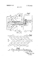
- FIG. 1 is a plan view on an enlarged scale of a belt portion as embodied according to the invention.
- FIG. 2 is a cross-sectional view taken along the line II-II of FIG. 1.
- FIG. 3 is a vertical cross-sectional view taken along the line III-III of FIG. 6, of a device in the at rest position for uniting together wood strips by employing the toothed member belt as shown in FIGS. 1 and 2.
- FIGS. 4 and 5 are detail views of the same device as shown in FIG. 3, to illustrate thetwo operational stages.
- FIG. 6' is a side elevation view showing the automatic mechanism for feeding the belt to the device.
- FIG. 7 is a close up plan view taken alongthe line VII-,VII of FIG. 6.
- the numeral 1 generally indicates the belt as employed according to the inventionto unite wooden strips.
- the belt 1 comprises a succession of planar metal members 2, forming an angle in their plane, and having teeth 3 which project perpendicularly thereto, the members 2 being united to each other at both their ends to two parallel bands 4,; which are parallel and made of the same metallic material.
- the teeth 3, moreover, can have anchoring extensions (not shown) projecting from their lateral surfaces.
- the device comprises a bedplate 10 to which a guiding member 1 l and a boxlike piece 20 are fastened by screws 25.
- a cylinder 15 and piston 16 unit Downwardly of the plate 14, there extends a cylinder 15 and piston 16 unit, fed through two ducts 17, 18 for v inducting andlor discharging, respectively, a fluid into the relevant chambers 48, 49 as defined by the piston 16 in the cylinder 15.
- the piston 16 has, integral therewith, a stem 19 which extends vertically, through the plate 14 and the guiding member 11, into the boxlike piece 20 aforementioned.
- the free end of the stem 19 is fitted with a punch 21, which is adapted to emerge from the piece 20, as will be explained in the following, through a complementary bore 24 formed through the top wall of the piece 20.
- the punch 21 has a shoulder 22, which cooperates with a stop abutment 23 of the piece 20, so as to limit the downward stroke.
- the stem 19, for convenience of assembly, is in two pieces, and these are united by a threaded collar 26, which, by cooperating with an abutment 27 of the guiding member 11, is also intended to limit the upward stroke of the punch 21.
- A-top the piece 20 is affixed, by screws 29, a supportingplate 28 having a rectangular longitudinal central opening 30 (FIG. 5).
- the longitudinal opposite edges of the opening 30 are stepped in their lower half and define with the outer surface of the top wall of the piece 20, guideways 31 for the belt 1.
- the plate 28 in addition, has an angular abutment ridge 32 for exactly positioning thereon the wood strips 33 to be joined: these latter, during the operation of the device, are firmly held on the plate 28, as will be explained hereinafter, by a pad 34, the latter being affixed to the top end plate 13.
- the belt 1, in the form of coils 35, is loaded on the device as shown in FIG. 6, and its leading end is brought, through the guideways 31, above the bore 24, through which the punch 21 can emerge.
- a stretcher 36 is inserted between the guideways and the coil 35.
- the stretcher 36 is affixed at one end at 37 to a shoulder 39 of the machine and its opposite end acts upon the belt 1 by urging it in the direction of the arrow.
- the belt 1 is automatically fed into the device, as will be explained hereinafter, by a lever 40 which is pivoted at an intermediate point 41 to the shoulder 39.
- One end of the lever 40 has a cam profile 42 which cooperates with a follower 43 mounted at the free end of an arm 44, the latter jutting from the plate 13.
- a pawl 46 whose free end acts between the teeth 3 of two consecutive members 2 of the belt 1; 47 is a recoil spring cooperating with the lever 40.
- the piston 16 and its stem 19 will slide upward and bring the punch 21 from the position of FIG. 4 to that of FIG. 5.
- the punch 21 severs by stamping a member 2 from the belt 1 driving the member 2 immediately after into the wooden strips which have been properly grooved at 50.
- the member 2 is severed from the side strips 4 of the belt 1, which remain at their place in the guideways 31 and emerge in front of them.
- the follower 43 will act upon the cam profile 42 of the lever 40, so that the latter will be rotated in the direction of the arrow F with its pawl 46, which, urging the teeth 3 of the member 2 place behind it, will cause the belt 1 to be fed forward through a step which sufficies to bring the first member 2 of the belt 1 to such a position as to be severed and driving into the wood strips to be joined, during the following operative cycle.
- the device could also be differently embodied without changing anything, at least as far as the scope of the invention is concerned.
- a method for joining wooden strips together characterized in that it employs a belt formed by a succession of planar metallic members forming an angle in their own plane and having teeth orthogonally projecting therefrom said members being integral at their ends to two strips of the same metallic material, wherefrom each of said members is severed by stamping and subsequently driven into the wooden strips to be joined.
- a device for severing from each other said members and for driving them into the wooden strips to be joined characterized in that it comprises guiding means for said strips to which the ends of each member are affixed, means for imparting a stepwise forward motion to said belt in a severing and driving-in station, and means for severing each member out of said strips and driving it subsequently into the wooden strips to be joined, as positioned in said station.
Applications Claiming Priority (1)
| Application Number | Priority Date | Filing Date | Title |
|---|---|---|---|
| IT2400870 | 1970-04-28 |
Publications (1)
| Publication Number | Publication Date |
|---|---|
| US3705452A true US3705452A (en) | 1972-12-12 |
Family
ID=11211450
Family Applications (1)
| Application Number | Title | Priority Date | Filing Date |
|---|---|---|---|
| US135602A Expired - Lifetime US3705452A (en) | 1970-04-28 | 1971-04-20 | Method and device for uniting wood strips together |
Country Status (5)
| Country | Link |
|---|---|
| US (1) | US3705452A (de) |
| BE (1) | BE766347A (de) |
| DE (1) | DE2119512A1 (de) |
| FR (1) | FR2090792A5 (de) |
| GB (1) | GB1349715A (de) |
Cited By (6)
| Publication number | Priority date | Publication date | Assignee | Title |
|---|---|---|---|---|
| US3837069A (en) * | 1971-11-12 | 1974-09-24 | H Nordgren | Method of securing fittings or plates onto containers or container portions and a machine for carrying out the method |
| US3939548A (en) * | 1972-12-20 | 1976-02-24 | Automated Building Components, Inc. | Methods for fabricating wooden frames and the like |
| US4033025A (en) * | 1974-04-19 | 1977-07-05 | Automated Building Components, Inc. | Methods for fabricating wooden frames and the like |
| US4047282A (en) * | 1972-12-20 | 1977-09-13 | Automated Building Components, Inc. | Method of joining wooden members |
| US4081893A (en) * | 1975-07-09 | 1978-04-04 | Automated Building Components, Inc. | Methods for forming wooden joints |
| US6460573B1 (en) * | 2000-01-31 | 2002-10-08 | Engel Industries | Companion duct system |
Families Citing this family (3)
| Publication number | Priority date | Publication date | Assignee | Title |
|---|---|---|---|---|
| FR2318715A1 (fr) * | 1975-07-22 | 1977-02-18 | Cassese Antoine | Dispositif d'agrafage et agrafe, notamment pour cadres de bois |
| CH628278A5 (de) * | 1977-06-21 | 1982-02-26 | Lega Norm Ag | Verfahren zum positionieren einer nagelplatte auf einem zurichtetisch und selbstklebendes halteelement zur durchfuehrung des verfahrens. |
| IT1158077B (it) * | 1982-03-02 | 1987-02-18 | Giacomet Corrado Fiorenza | Macchina aggraffatrice automatica a partire da nastro metallico |
Citations (2)
| Publication number | Priority date | Publication date | Assignee | Title |
|---|---|---|---|---|
| US3413703A (en) * | 1966-07-26 | 1968-12-03 | Sanford Arthur C | Method for fabricating trusses in horizontal position |
| US3513530A (en) * | 1967-11-06 | 1970-05-26 | Axel Karl Rosenblom | Method for nailing together molding boards in the construction of molds |
-
1971
- 1971-04-20 US US135602A patent/US3705452A/en not_active Expired - Lifetime
- 1971-04-20 GB GB1011171*[A patent/GB1349715A/en not_active Expired
- 1971-04-22 DE DE19712119512 patent/DE2119512A1/de active Pending
- 1971-04-27 FR FR7114978A patent/FR2090792A5/fr not_active Expired
- 1971-04-27 BE BE766347A patent/BE766347A/xx unknown
Patent Citations (2)
| Publication number | Priority date | Publication date | Assignee | Title |
|---|---|---|---|---|
| US3413703A (en) * | 1966-07-26 | 1968-12-03 | Sanford Arthur C | Method for fabricating trusses in horizontal position |
| US3513530A (en) * | 1967-11-06 | 1970-05-26 | Axel Karl Rosenblom | Method for nailing together molding boards in the construction of molds |
Cited By (7)
| Publication number | Priority date | Publication date | Assignee | Title |
|---|---|---|---|---|
| US3837069A (en) * | 1971-11-12 | 1974-09-24 | H Nordgren | Method of securing fittings or plates onto containers or container portions and a machine for carrying out the method |
| US3939548A (en) * | 1972-12-20 | 1976-02-24 | Automated Building Components, Inc. | Methods for fabricating wooden frames and the like |
| US4047282A (en) * | 1972-12-20 | 1977-09-13 | Automated Building Components, Inc. | Method of joining wooden members |
| US4033025A (en) * | 1974-04-19 | 1977-07-05 | Automated Building Components, Inc. | Methods for fabricating wooden frames and the like |
| US4081893A (en) * | 1975-07-09 | 1978-04-04 | Automated Building Components, Inc. | Methods for forming wooden joints |
| US6460573B1 (en) * | 2000-01-31 | 2002-10-08 | Engel Industries | Companion duct system |
| US6810570B2 (en) * | 2000-01-31 | 2004-11-02 | Engel Industries, Inc. | Method of attaching a connector element to a duct flange |
Also Published As
| Publication number | Publication date |
|---|---|
| FR2090792A5 (de) | 1972-01-14 |
| DE2119512A1 (de) | 1971-11-18 |
| GB1349715A (en) | 1974-04-10 |
| BE766347A (fr) | 1971-09-16 |
Similar Documents
| Publication | Publication Date | Title |
|---|---|---|
| US3811171A (en) | Pierce nut applying tool | |
| US3705452A (en) | Method and device for uniting wood strips together | |
| US3877133A (en) | Pierce nut applying method | |
| US3633811A (en) | Apparatus to drive various fastening means | |
| US5887339A (en) | Device for use in a press for feed of fasteners and for their attachment in workpieces by pressing | |
| CN106583524B (zh) | 一种自动冲盖机及其方法 | |
| US3851373A (en) | Method and apparatus for attachment of a nut in the inside wall of a pipe | |
| US2320703A (en) | Wire-stitching machine | |
| US3095588A (en) | Apparatus for forming nails from wire stock | |
| US3265275A (en) | Apparatus for attaching pronged devices to fabric or other flexible material | |
| US3771709A (en) | Setting of wall anchors and analogous objects | |
| US1298172A (en) | Jig-filling mechanism. | |
| US1947956A (en) | Fastener forming and assembling machine and method of securing fastener elements to tape | |
| US2804622A (en) | Clip-forming and clinching mechanisms | |
| US1943990A (en) | Reenforcing cinematograph film | |
| US2953788A (en) | Carpet tack strip fabricating apparatus | |
| US2442859A (en) | Metal forming machine | |
| US1841820A (en) | Method of sheet metal stamping | |
| US2329202A (en) | Machine for forming clips and connecting wire members together thereby | |
| US2852059A (en) | Machine for forming and notching strip for box reinforcing rims | |
| US2409968A (en) | Machine for operating on materials | |
| US3154234A (en) | Strip-feeder subassembly | |
| US1331884A (en) | Sheet-metal forming and setting machine | |
| US3225795A (en) | Machine for forming an eye at either end of a wire binder on wirebound box components | |
| US3724257A (en) | Apparatus for manufacturing thin wall flexible bearing liners |