US3704024A - Brake mechanism attached to a ski - Google Patents
Brake mechanism attached to a ski Download PDFInfo
- Publication number
- US3704024A US3704024A US113211A US3704024DA US3704024A US 3704024 A US3704024 A US 3704024A US 113211 A US113211 A US 113211A US 3704024D A US3704024D A US 3704024DA US 3704024 A US3704024 A US 3704024A
- Authority
- US
- United States
- Prior art keywords
- braking
- ski
- retaining
- pawl
- preparatory
- Prior art date
- Legal status (The legal status is an assumption and is not a legal conclusion. Google has not performed a legal analysis and makes no representation as to the accuracy of the status listed.)
- Expired - Lifetime
Links
- 230000007246 mechanism Effects 0.000 title claims abstract description 67
- 230000027455 binding Effects 0.000 claims abstract description 22
- 238000009739 binding Methods 0.000 claims abstract description 22
- 238000010276 construction Methods 0.000 claims description 12
- 230000009471 action Effects 0.000 claims description 9
- 230000000994 depressogenic effect Effects 0.000 claims description 6
- 230000002708 enhancing effect Effects 0.000 claims 1
- 210000001331 nose Anatomy 0.000 description 20
- 230000000881 depressing effect Effects 0.000 description 4
- 230000000717 retained effect Effects 0.000 description 4
- 230000008901 benefit Effects 0.000 description 2
- 238000006073 displacement reaction Methods 0.000 description 2
- 230000000414 obstructive effect Effects 0.000 description 2
- 244000182067 Fraxinus ornus Species 0.000 description 1
- 230000001174 ascending effect Effects 0.000 description 1
- 230000000694 effects Effects 0.000 description 1
- 238000004519 manufacturing process Methods 0.000 description 1
- 230000004048 modification Effects 0.000 description 1
- 238000012986 modification Methods 0.000 description 1
- 239000011435 rock Substances 0.000 description 1
- 230000007704 transition Effects 0.000 description 1
Images


Classifications
-
- A—HUMAN NECESSITIES
- A63—SPORTS; GAMES; AMUSEMENTS
- A63C—SKATES; SKIS; ROLLER SKATES; DESIGN OR LAYOUT OF COURTS, RINKS OR THE LIKE
- A63C5/00—Skis or snowboards
- A63C5/06—Skis or snowboards with special devices thereon, e.g. steering devices
- A63C5/061—Ski-boot sole-scrapers
-
- A—HUMAN NECESSITIES
- A63—SPORTS; GAMES; AMUSEMENTS
- A63C—SKATES; SKIS; ROLLER SKATES; DESIGN OR LAYOUT OF COURTS, RINKS OR THE LIKE
- A63C7/00—Devices preventing skis from slipping back; Ski-stoppers or ski-brakes
- A63C7/10—Hinged stoppage blades attachable to the skis in such manner that these blades can be moved out of the operative position
- A63C7/1006—Ski-stoppers
- A63C7/106—Ski-stoppers articulated about a longitudinal axis
Definitions
- a brake mechanism adapted to be secured to a ski for braking the ski comprises at least one brake element movable, upon release of the boot from the ski binding, from a position above the running surface of the ski automatically downwardly into a ski braking position, to thereby engage with the snow for the purpose of exerting a braking force upon the ski.
- a retaining element actuatable upon inserting the boot into the ski binding retains the braking element in its preparatory braking position, so that upon release of such retaining element the braking element moves from its preparatory braking position into its actual ski braking position.
- a first locking-pawl arrangement serves to retain the braking element in a locked position for convenient transport and storage of the ski, and a second locking-pawl arrangement serves to retain such braking element in its preparatory braking position,
- this retaining element cooperating with said first locking-pawl arrangement and said second lockingpawl arrangement such that actuation of said retaining element causes release of the locked position of said braking element and transfer thereof into its preparatory braking position against a spring force effective at said retaining element.
- the present invention relates to a new and improved brake mechanism secured to a ski, this brake mechanism being of the type incorporating at least one brake element which, upon removing the ski boot from the binding, automatically moves from a position above the running surface of the ski downwardly into a braking position, thereby generating a braking force for the ski in the snow.
- the brake mechanism of the invention embodies a retaining element actuated by the ski boot, this retaining element serving to retain the brake element in a preparatory position, so that upon release of the retaining element the brake element assumes its ski-braking position.
- Brake mechanisms of the prior art which have been proposed for braking the ski upon release from the boot possess the drawback that the brake element, during such time as the ski is no longer coupled with the boot, either is located in the ski braking position and therefore, for instance, during carrying or transport of the ski is obstructive and dangerous, or else such braking element is retained by a locking mechanism in a position above the running surface of the ski.
- the use of a locking mechanism to retain the brake element in this raised position has been found to be quite disadvantageous for a brake mechanism, which simultaneously constitutes an important safety feature for the ski, and in fact has been found to be even dangerous. This is so because the possibility readily exists that when using the ski the skier forgets to release the locking mechanism for the brake element.
- a standard locking mechanism of the type proposed in the prior art has the additional drawback that it must be manually actuated, therefore requires the attention of the skier and, in fact, counteracts the purpose of modern day bindings which allow a skier to insert the boot into the skiwithout having to bend over.
- a primary objective of the instant invention is to provide a brake mechanism of the mentioned type which effectively and reliably fulfills the existing need in the art and overcomes the aforementioned prevailing draw.- hacks existing with the prior art constructions of this type.
- Another and more specific object'of the instant invention is -to provide a brake mechanism for a ski in which the brake element, when the ski boot is released from the ski, is located in a position above the lower edge of the ski, and only after connecting the boot with the ski and after actuating the retaining element, and specifically upon release of the boot from the ski and after release of the retaining element, can such brake element move into the ski braking position.
- An additional object of the invention is to provide a brake mechanism of the mentioned type which is of relatively simple design, economical to manufacture, extremely reliable in operation, does not require the particular attention of the skier to be placed into operation, in other words automatically assumes a preparatory braking position when the boot is inserted into the ski and automatically moves into its ski braking position when the skier thereafter falls and the ski is released from the boot, and thereby renders it impossible to prevent such braking'mechanism from carrying out its intended function.
- the brake mechanism of the present invention is manifested by the features that the brake element is retained in an arrested or locked position by means of a first locking pawl arrangement and is retained in its preparatory position by means of a second locking-pawl arrangement. Release of the arrested or locking position and the transition into the preparatory position is undertaken after actuating a retaining element against a resilient or spring force effective at the retaining element.
- FIG. 1 is a front or end view, with the skishown in' section, of a first embodiment of brake mechanism attached, to the ski and with the brake element depicted in its braking position;
- FIG. 2 is a side view of the braking mechanism depicted in FIG. 1, yet this time with the brake element located in its arrested or locked position;
- FIG. 3 is a fragmentary side view of the arrangement of FIG. 2, yet this time showing the brake element in its preparatory position;
- FIG. 4 is a top plan view of the brake mechanism attached to the ski for the arrangement of FIG. 1;
- FIG. 5 is a further embodiment of inventive brake mechanism showing details of the pawls and the control body or element;
- FIG. 6 illustrates a modified version-of the braking element
- FIG. 7 illustrates a still further modification of the brake element which now is shown as formed as a bipartite ortwo-piece body member
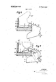
- FIG. 8 is an end view, similar to FIG. 1;, of a different brake mechanism employing two brake elementstand
- FIG. 9' is a sectional view through the brake mechanism of FIG. 8, taken substantially along'the lines IX-IX thereof.
- a bearing bracket '2 in any suitable fashion, for instance through the use of screws by way of example.
- the bearing bracket 2 is equipped at one side with two upstanding straps or plates 3 and 4 and at the opposite side with a similarly upstanding leg 5 having a slot 6.
- the straps 3 and 4 are bored through for the purpose of receiving in piercing relationship a bolt member 7, at the cylindrical portion of which there is mounted a plate-shaped brake element 10.
- Brake element is rocked or pivoted into the position depicted in FIG.
- FIG. 1 also shows in phantom lines the position 10' which the brake element 2 assumes when located in its blocked or arrested position as well as in its preparatory position. In that case, and again as best observed by referring to FIG. 1', the .brake element 10 is then disposed at the upper surface of the ski, while, when it assumes its ski braking position, such brake element then depends downwardly beneath the running surface of the associated ski l.
- FIGS. 2 and 3 showing the details of the brake mechanism of the ar-- rangement of FIG. 1, two pawls 13 and 14, or equivalent devices, are arranged at the leg member 5.
- These pawls l3 and 14 are pivotably mounted at the pins or pivot bolts 15 and 16, respectively, and a pressure spring 17 is shown arranged between pawls l3 and I4.
- Pressure spring 17 serves to press the pawls l3 and I4 against noses or cams l8 and 19 respectively, provided at a control body or element 20.
- Control body 20 is pivotably mounted at the upstanding leg member 5 with the aid of the pivot pin 21.
- the braking element 10 possesses two arresting or locking members 25, 26, which, when the braking element It) assumes its arresting and preparatory positions, are disposed between the pawls 13,14.
- the locking portion or member is intended to cooperate with the pawl 13 (FIG. 2), while the otherlocking or arresting member 26 is intended to cooperate with the pawl 14 (FIG. 3).
- reference character 30 serves to designate a retaining or holding bracket which is secured at one end in a bore 31 provided at the bearing bracket 2, the other end of this retaining or holding bracket 30 being engageable with a bore 32 of the control body 20, as best observed by specifically referring to FIG. I.
- the retaining bracket 30 is of preferably resilient construction so that it protrudes upwardly away from the surface of the ski when it is not tensioned, as shown in FIG.2, while when depressing this retaining bracket 30, into the position shown in FIG. 3, such bearsagainst the top or upper surface of the ski and simultaneously rocks the control body 20, specifically into the position shown in FIG. 3.
- FIG. 5 illustrates a modified construction of the control body or control element, which here has been designated by reference character 20'. While the construction of this control body 20 is somewhat different from the previously considered control body or element 20, the function is the same. Control body 20' together with the pawl 34 is formed as an integral element, while the other pawl 33 is of resilient construction, and is inserted in a receiving notch at the lower region of the control element or body 20'. Just as was the case for the brake element 10 of the embodiment of FIGS. 1 to 4, here the brake element 10" likewise has a pair of arresting or locking nose members 35 and 36 destined to cooperate with the pawls 33 and 34 respectively.
- FIG. 6 illustrates a further embodiment of the braking element, this time designated by reference character 40.
- Braking element is constructed in such a way that it extends beneath the running surface of the ski 1 when it assumes its ski braking position. This in contrast to the operation of the'brake element 10 of the arrangement of FIG. 1 which while depending from the ski into a position lower thantherunning or bottom surface of the 'ski, still'does not extend beneath the running surface of the ski.
- the braking surface of such brake element 40 is enlarged and, additionally, there is improved the braking action of the brake mechanism particularly then when encountering snow conditions where the snow is relatively hard.
- the braking action can be intensified by providing a serrated or toothed portion 41 at the brake element 40, particularly effective under icy conditions of the piste.
- a similar serrated arrangement 40 can be likewise provided for the embodiment of FIG. 1.
- the arresting and rest position of the brake element 40 has been shown in phantom lines at location 40'. In all other respects, it will be evident that the brake mechanism of this embodiment may function similar to the embodiments heretofore discussed in conjunction with FIGS. 1 to 5 inclusive.
- FIG. 7 illustrates an embodiment incorporating a modified construction of the brake element which here is shown formed from the two brake element portions 50 and 51 articulated or hinged to one another by a pivot pin 52.
- the brake element portion 51 will be seen to be equipped with a cut-out or recess 53 into which depends or extends the other brake element portion 50.
- the end 11' of the otherwise not-visible torsion spring, corresponding to torsion spring 11 of FIG. 4 presses upon a pin 54, in this way causing both brake element portions 50 and 51 to assume their ski braking position.
- both brake element porportion 51 is advantageously equipped with a serrated portion 41 improving the braking action when the piste 1S icy.
- FIG. 8 illustrates a construction of brake mechanism in which two separate brake elements 60 and 61 are arranged in such a fashion that they are located at opposite longitudinal sides of the ski and, upon assuming the braking position depicted in solid lines in FIG. 8, engage beneath the associated ski l.
- the advantage of this type of arrangement resides in the fact that the spring 11 (FIGS. 2, 3 and 4) for rocking the brake elements 60 and 61 does not have to be designed so strongly, particularly since even during lateral displacement of the ski at least one of the brake elements 60 or 61 is in its effective braking position.
- the spring 11 In the constructions discussed above where only one brake element depends from one longitudinal side or edge of the ski, the spring 11 must possess a construction and design of sufficient strength to prevent any upward tilting or rocking of the brake element during lateral displacement of the ski towards one side, otherwise the action of the brake mechanism becomes ineffectual.
- FIG. 8 In the arrangement of FIG. 8, two bearing brackets 2 equipped with the straps 3 for mounting the brake elements 60 and 61 are arranged atthe uppersurface of the ski in the same way as was described for. the arrangement of FIGS. 1 to 4.
- the rocked or arrested position of both brake elements 60 and 61 has been shown in FIG. 8 by the phantom lines. Both of the'brake elements 60 and 61 can be pulled into this locked or arrested position out of the braking position through the use of any suitable device, such as for instance non-illustrated traction cables.
- both of the braking elements 60 and 61 each are equipped with two locking nose members 25 and 26 which engage with the associated pawls 63 and 64 for the reasons discussed heretofore.
- the pawls 63 and 64 together with the control body or element 65 form an integral component mounted by means of a bolt or pivot pin 66 so as to be pivotal at the vertically or upright extending legs 67 of the bearing brackets 2.
- These bearing brackets 2 possess a sufficient thickness so that the pawls 25 and 26 of both brake elements 60 and 61 can engage with the control element 65.
- the legs 67 of the bearing brackets 2 will be seento be equipped with laterally protruding flaps or lip portions 68 and form a housing for receiving the control body or element 65.
- the braking element 60 has been depicted in its arrested position. It can be constructed of a number of components, whereby then the individual components are retained together by flexible connection elements 69, for instance formed of plastic or rubber. I-Iere also the brake elements 60 and 61 can be equipped with a serrated portion 70 and 71, respectively, improving the hooking action into the snow of these braking elements particularly when encountering hard snow or icy conditions.
- control element 65of FIG. 9 The mode of operation of the control element 65of FIG. 9 is similar to the embodiments heretofore discussed.
- This control element 65 possesses a projection or extended portion 72' at which there is anchored the above-discussed retaining or holding bracket, here designated by reference character 73.
- This holding bracket 73 advantageously corresponds to the holding or retaining bracket 30 of the embodiments of FIGS. 2, 3 and S, and is configured such that it retains the control element 65 in the position of FIG. 9 where the locking nose member 25, upon raising the associated braking element, can ratchet or engage with the pawl 63.
- the arresting pawl 63 Upon depressing the retaining bracket 73 with the aid of the ski boot, and specificallyagainst the spring force acting at the retaining bracket, the arresting pawl 63 is released and the brake elements 60, 61 engage by means of the locking nose means 26 with the preparatory pawl 64. Now, if the retaining bracket 73 is released, for instance on the occasion of the skier taking a fall, then it springs back and due to rocking of the control body 65 releases the pawl 64, so that the corresponding brake element is'rocked under spring force into the ski braking position.
- the retaining bracket 73 would then be depressed discussed herein are advantageously arranged at the region of the ski binding of each ski.
- the brake mechanism can be, for instance, mounted at the ski plate carrying one of the ski binding portions, so that such ski binding and brake mechanism form an integral unit.
- All of the described brake mechanisms are equipped with brake elements which are rocked in a plane transverse to the lengthwise or longitudinal axis of the associated ski.
- the pivot axis for such brake element or brake elements is arranged parallel to the longitudinal axis of the ski.
- a brake mechanism adapted to be secured to a ski having a ski binding for braking the ski comprising at least one braking element which upon release of the ski boot from the ski binding is automatically movable from a preparatory braking position disposed above the running surface of the ski downwardly into a ski braking position, to thereby engage the snow for the purpose of exerting a braking force upon the ski, a retaining element which can be actuated-upon inserting the ski boot into the ski binding for retaining said braking element in its preparatory braking position, so that upon release of said retaining element said braking element moves from said preparatory braking position into said ski braking position, a first locking-pawl arrangement for retaining said braking element in a locked position for convenient transport and storage of the ski, a second locking-pawl arrangement for retaining said braking element in said preparatory braking position, said retaining element cooperating with said first locking-pawl arrangement and said second locking-pawl arrangement such that actuation of said retaining element causes release of the locked
- a brake mechanism adapted to be secured to a ski having a ski binding for braking the ski comprising at least one braking element which upon release of the ski boot from the ski binding is automatically movable from a preparatory braking position disposed above the running surface of the ski downwardly into a ski braking position, to thereby engage the snow for the purpose of exerting a braking force upon the ski, a retaining element which can be actuated upon inserting the ski boot into the ski binding for retaining said braking element in its preparatory braking position, so that upon release of said retaining element said braking element moves from said preparatory braking position into said ski braking position, a first locking-pawl arrangement for retaining said braking element in a locked position for convenient transport and storage of the ski, a second locking-pawl arrangement for retaining said braking element in said preparatory braking position, said retaining element cooperating with said first locking-pawl arrangement and said second locking-pawl arrangement such that actuation of said retaining element causes release of the locked position of
- said retaining element comprises a resilient bracket which can be depressed by the ski boot of the user, said resilient bracket having an end mounted at said control element.
- said braking element possesses a bipartite construction defined by two braking element portions, one braking element portion of said braking element being provided with a slot into which extends the other braking element portion of said braking element, and both portions of said braking element being pivotably cou-
Landscapes
- Footwear And Its Accessory, Manufacturing Method And Apparatuses (AREA)
Applications Claiming Priority (2)
| Application Number | Priority Date | Filing Date | Title |
|---|---|---|---|
| CH226270A CH507719A (de) | 1970-02-17 | 1970-02-17 | An einem Ski befestigbare Bremsvorrichtung |
| CH20071A CH525013A (de) | 1970-02-17 | 1971-01-07 | An einem Ski befestigbare Bremsvorrichtung |
Publications (1)
| Publication Number | Publication Date |
|---|---|
| US3704024A true US3704024A (en) | 1972-11-28 |
Family
ID=25683855
Family Applications (1)
| Application Number | Title | Priority Date | Filing Date |
|---|---|---|---|
| US113211A Expired - Lifetime US3704024A (en) | 1970-02-17 | 1971-02-08 | Brake mechanism attached to a ski |
Country Status (7)
| Country | Link |
|---|---|
| US (1) | US3704024A (de) |
| JP (1) | JPS5117101B1 (de) |
| AT (2) | AT312479B (de) |
| CA (1) | CA925531A (de) |
| CH (1) | CH525013A (de) |
| DE (2) | DE7104814U (de) |
| FR (1) | FR2078611A5 (de) |
Cited By (12)
| Publication number | Priority date | Publication date | Assignee | Title |
|---|---|---|---|---|
| US3877709A (en) * | 1972-12-05 | 1975-04-15 | Altenburger Karl | Ski brake |
| US3899185A (en) * | 1972-03-08 | 1975-08-12 | Hans Martin | Ski brake mechanism |
| US3917297A (en) * | 1972-09-13 | 1975-11-04 | Jakob Fruh | Device to be attached to a ski for preventing ski runaway |
| US3918730A (en) * | 1974-11-29 | 1975-11-11 | Olin Corp | Ski stopper |
| US4018455A (en) * | 1974-04-19 | 1977-04-19 | Hans Bieler | Braking device for skis |
| US4171827A (en) * | 1978-03-20 | 1979-10-23 | Paul Gley | Ski brake |
| US4342468A (en) * | 1978-04-05 | 1982-08-03 | Ste Look | Ski brake |
| US20040140637A1 (en) * | 2002-10-11 | 2004-07-22 | Travis Cook | Ski vehicle emergency ski brake system |
| US6866273B2 (en) | 2000-12-08 | 2005-03-15 | The Burton Corporation | Sliding device |
| US20050077119A1 (en) * | 2003-10-10 | 2005-04-14 | Eryn Houston | Braking apparatus and method for making and using the same |
| JP2007504865A (ja) * | 2003-09-08 | 2007-03-08 | エフエスユー マニュファクチュアリング プロプライエタリィ リミテッド | スノーボード制動機 |
| US20130341127A1 (en) * | 2012-06-20 | 2013-12-26 | Samuel J. Mann | Control System for Downhill Skis |
Families Citing this family (5)
| Publication number | Priority date | Publication date | Assignee | Title |
|---|---|---|---|---|
| DE2417279C3 (de) * | 1973-04-13 | 1984-09-20 | Hans Rapperswil Wehrli | Skistopper |
| FR2228506A1 (en) * | 1973-05-11 | 1974-12-06 | Beyl Jean Joseph Alfred | Brake to hold ski at rest when unworn - has spring loaded pivoting anchor arms held reracted by ski boot |
| FR2228504A1 (en) * | 1973-05-11 | 1974-12-06 | Beyl Jean Joseph Alfred | Brake to anchor ski when unworn - has spring loaded anchor tines held retracted by ski boot on ski |
| DE2600850A1 (de) * | 1976-01-12 | 1977-07-14 | Karl Altenburger | Bremsvorrichtung fuer skier |
| FR2425253A1 (fr) * | 1978-05-09 | 1979-12-07 | Look Sa | Frein a ski |
Citations (5)
| Publication number | Priority date | Publication date | Assignee | Title |
|---|---|---|---|---|
| DE100284C (de) * | ||||
| AT216398B (de) * | 1957-11-26 | 1961-07-25 | Earl Andrew Miller | Sicherheitsvorrichtung an Skiern |
| US3048418A (en) * | 1957-02-14 | 1962-08-07 | Gertsch Ernst | Ski-stopping device |
| US3083028A (en) * | 1958-01-15 | 1963-03-26 | Earl A Miller | Ski stop |
| US3433494A (en) * | 1966-09-07 | 1969-03-18 | Hans Hinterholzer | Brake attachment for ski |
-
1971
- 1971-01-07 CH CH20071A patent/CH525013A/de unknown
- 1971-02-08 US US113211A patent/US3704024A/en not_active Expired - Lifetime
- 1971-02-09 DE DE7104814U patent/DE7104814U/de not_active Expired
- 1971-02-09 DE DE19712106108 patent/DE2106108A1/de active Pending
- 1971-02-12 AT AT00652/72A patent/AT312479B/de active
- 1971-02-12 AT AT121771A patent/AT305110B/de not_active IP Right Cessation
- 1971-02-15 FR FR7105034A patent/FR2078611A5/fr not_active Expired
- 1971-02-16 CA CA105551A patent/CA925531A/en not_active Expired
- 1971-02-17 JP JP717027A patent/JPS5117101B1/ja active Pending
Patent Citations (5)
| Publication number | Priority date | Publication date | Assignee | Title |
|---|---|---|---|---|
| DE100284C (de) * | ||||
| US3048418A (en) * | 1957-02-14 | 1962-08-07 | Gertsch Ernst | Ski-stopping device |
| AT216398B (de) * | 1957-11-26 | 1961-07-25 | Earl Andrew Miller | Sicherheitsvorrichtung an Skiern |
| US3083028A (en) * | 1958-01-15 | 1963-03-26 | Earl A Miller | Ski stop |
| US3433494A (en) * | 1966-09-07 | 1969-03-18 | Hans Hinterholzer | Brake attachment for ski |
Cited By (15)
| Publication number | Priority date | Publication date | Assignee | Title |
|---|---|---|---|---|
| US3899185A (en) * | 1972-03-08 | 1975-08-12 | Hans Martin | Ski brake mechanism |
| US3917297A (en) * | 1972-09-13 | 1975-11-04 | Jakob Fruh | Device to be attached to a ski for preventing ski runaway |
| US3877709A (en) * | 1972-12-05 | 1975-04-15 | Altenburger Karl | Ski brake |
| US4018455A (en) * | 1974-04-19 | 1977-04-19 | Hans Bieler | Braking device for skis |
| US3918730A (en) * | 1974-11-29 | 1975-11-11 | Olin Corp | Ski stopper |
| US4171827A (en) * | 1978-03-20 | 1979-10-23 | Paul Gley | Ski brake |
| US4342468A (en) * | 1978-04-05 | 1982-08-03 | Ste Look | Ski brake |
| US6866273B2 (en) | 2000-12-08 | 2005-03-15 | The Burton Corporation | Sliding device |
| US20040140637A1 (en) * | 2002-10-11 | 2004-07-22 | Travis Cook | Ski vehicle emergency ski brake system |
| JP2007504865A (ja) * | 2003-09-08 | 2007-03-08 | エフエスユー マニュファクチュアリング プロプライエタリィ リミテッド | スノーボード制動機 |
| EP1663412A4 (de) * | 2003-09-08 | 2009-05-06 | Fsu Mfg Pty Ltd | Snowboard-bremse |
| US20050077119A1 (en) * | 2003-10-10 | 2005-04-14 | Eryn Houston | Braking apparatus and method for making and using the same |
| US6971483B2 (en) * | 2003-10-10 | 2005-12-06 | Eryn Houston | Braking apparatus and method for making and using the same |
| US20130341127A1 (en) * | 2012-06-20 | 2013-12-26 | Samuel J. Mann | Control System for Downhill Skis |
| US8905199B2 (en) * | 2012-06-20 | 2014-12-09 | Samuel J. Mann | Control system for downhill skis |
Also Published As
| Publication number | Publication date |
|---|---|
| FR2078611A5 (de) | 1971-11-05 |
| CH525013A (de) | 1972-07-15 |
| JPS5117101B1 (de) | 1976-05-31 |
| AT312479B (de) | 1973-11-15 |
| AT305110B (de) | 1973-02-12 |
| CA925531A (en) | 1973-05-01 |
| DE2106108A1 (de) | 1971-08-26 |
| DE7104814U (de) | 1975-11-27 |
Similar Documents
| Publication | Publication Date | Title |
|---|---|---|
| US3704024A (en) | Brake mechanism attached to a ski | |
| US3715126A (en) | Device for catching a runaway ski | |
| US4087113A (en) | Ski brake | |
| US3048418A (en) | Ski-stopping device | |
| US4722613A (en) | Cross-country ski binding | |
| US4082312A (en) | Cross country ski binding | |
| US3578349A (en) | Safety ski binding | |
| US4765640A (en) | Cross-country ski binding | |
| US5014571A (en) | Bicycle pedal with a releasable binding | |
| US4521032A (en) | Brake device for skis | |
| US4036509A (en) | Ski brake apparatus | |
| US4061356A (en) | Safety arrangement for a ski | |
| US2879071A (en) | Ski binding having automatically releasable heel anchor | |
| US20180093162A1 (en) | Mechanism for locking longitudinally a ski-binding on a mounting plate | |
| US4231584A (en) | Ski boot heel binding equipped with ski brake | |
| US4129319A (en) | Ski bindings | |
| US4489956A (en) | Heelholder for safety ski bindings | |
| US3433494A (en) | Brake attachment for ski | |
| US3900205A (en) | Ski safety binding | |
| US4061357A (en) | Ski binding having a releasable boot plate provided with a ski brake | |
| US3899185A (en) | Ski brake mechanism | |
| US3830510A (en) | Releasable heel holddown mechanism for ski bindings | |
| US3794336A (en) | Ski binding with ski brake | |
| US3917297A (en) | Device to be attached to a ski for preventing ski runaway | |
| US3715127A (en) | Ski binding with clamping bail |