US3674633A - Headbox for a paper machine providing for simultaneous adjustment of the front wall and mixing roll therein - Google Patents
Headbox for a paper machine providing for simultaneous adjustment of the front wall and mixing roll therein Download PDFInfo
- Publication number
- US3674633A US3674633A US27499A US3674633DA US3674633A US 3674633 A US3674633 A US 3674633A US 27499 A US27499 A US 27499A US 3674633D A US3674633D A US 3674633DA US 3674633 A US3674633 A US 3674633A
- Authority
- US
- United States
- Prior art keywords
- front wall
- bottom plate
- slide
- headbox
- mixing roller
- Prior art date
- Legal status (The legal status is an assumption and is not a legal conclusion. Google has not performed a legal analysis and makes no representation as to the accuracy of the status listed.)
- Expired - Lifetime
Links
- 238000006073 displacement reaction Methods 0.000 abstract description 13
- 239000012530 fluid Substances 0.000 description 4
- 230000006872 improvement Effects 0.000 description 4
- 238000007789 sealing Methods 0.000 description 3
- 230000009471 action Effects 0.000 description 2
- 230000008859 change Effects 0.000 description 2
- 230000035508 accumulation Effects 0.000 description 1
- 238000009825 accumulation Methods 0.000 description 1
- 230000001154 acute effect Effects 0.000 description 1
- 230000008901 benefit Effects 0.000 description 1
- 230000005540 biological transmission Effects 0.000 description 1
- 230000001627 detrimental effect Effects 0.000 description 1
- 238000010586 diagram Methods 0.000 description 1
- 239000000835 fiber Substances 0.000 description 1
- 239000007788 liquid Substances 0.000 description 1
- 238000012986 modification Methods 0.000 description 1
- 230000004048 modification Effects 0.000 description 1
- 239000000725 suspension Substances 0.000 description 1
Images


Classifications
-
- D—TEXTILES; PAPER
- D21—PAPER-MAKING; PRODUCTION OF CELLULOSE
- D21F—PAPER-MAKING MACHINES; METHODS OF PRODUCING PAPER THEREON
- D21F1/00—Wet end of machines for making continuous webs of paper
- D21F1/02—Head boxes of Fourdrinier machines
Definitions
- the mixing roller has been arranged in the event of displacement of the adjustable front wall in the direction parallel to the bottom plate to be displaced parallel to the bottom plate through the same distance and the mixing roller has been arranged in the event of the adjustable front wall being displaced through the distance (a) in the direction perpendicular to the bottom plate to be displaced parallel to the bottom plate through the distance a/tan a.
- the invention relates to the field of paper machine headboxes.
- the object of the present invention is to provide an adjustable front wall and mixing roller design for headboxes in which the roller follows along with the movement of the front wall so that its distance from the front wall and from the bottom plate remains unchanged.
- the headbox according to the invention offers the advantage of providing an arrangement in which the upper lip of the slice portion is adjustable horizontally as well as vertically, yet without causing any changes in the distance of the front wall and bottom of the headbox from the mixing roller closest to the slice portion.
- FIG. 1 displays in the manner of a sketch the design principle of a headbox according to the invention, in longitudinal section.
- FIG. 2 shows the slice portion of a headbox according to the invention, with mechanical design solution, in elevational view.
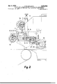
- FIG. 3 shows the same as FIG. 2, viewed from above.
- FIG. 4 shows a hydraulic or pneumatic design solution in elevational view.
- FIG. 5 shows an electrified design solution
- FIG. 6 shows the circuit diagram of the electrical solution.
- the front wall and mixing roller have been mutually coupled by means of a mechanical, hydraulic, pneumatic or electrical transmission in such manner that when the front wall is displaced parallelly with reference to the bottom plate the position of the mixing roller with reference to the front wall does not change.
- the mixing roller is displaced in a direction parallel to the bottom plate, whereby its position with reference to the front wall changes, but the gap between the front wall and the roller remains unchanged.
- FIG. 1 shows the structural principle of the headbox in question.
- the component 1 is the adjustable front wall, and 3 is the fixed front wall, 2 is the mixing roller, and 4 is the bottom plate of the box.
- the angle between the front wall and the bottom plate, oz, is the lip angle, 5 is a sealing component which follows along with the movement of the adjustable front wall parallel to the bottom plate.
- FIG. 2 shows a mechanical device according to the invention in elevational view and FIG. 3 shows the same, viewed from above, 6 is the side plate of the box, to which the operating unit 7 for the movement of the front wall in the direction perpendicular to the bottom plate has been attached.
- the operating unit comprises a worm gear 9 with a threaded hole and, inside this hole, a threaded spindle 11, which moves when the gear 9 is rotated by means of the hand wheel 13 or alternatively by motor drive.
- One end of the spindle 11 has been attached to the slide element 15, which is guided in its movement by the guides 16 and 17.
- an operating unit 8 comprising a hand wheel 14, worm gear and spindle 12, one end of the latter being attached to the slide element 18 guided with reference to the slide element and which moves parallel to the bottom plate when the worm gear 10 is rotated by the hand wheel or alternatively by motor drive.
- the slide element 18 has been attached to the adjustable front wall 11 and it is rigidly connected with the tooth rack '19, which is perpendicular to the bottom plate, and to the guiding fork 20 (see FIG. 3).
- On the side wall guides 21, 22 have been fixed, by which the slide 23 is guided in its movements.
- the slide element 23 carries a pin 24, on which the gears 25, 26 have been rotatably journalled (see FIG. 3), which have been mutually connected so that they revolve both together.
- the gear 26 meshes with the tooth rack 19 and the gear 25, with a tooth rack 27 parallel to the bottom plate, which is free to move in the direction parallel to the bottom plate and to displace the mixing roller in this direction.
- the mixing roller is journalled on the slide element 28 (see FIG. 3), to which the tooth rack 27 has been attached, and it is guided by the guides 29, 30. Between the slide element 28 and the side plate a gasket has been inserted.
- the diameters of the gears have been chosen so that if the displacement of the front wall at right angles to the bottom plate is a and the lip angle is a, the displacement of the mixing roller parallel to the bottom plate will be a/ tan a.
- the shaft of the gears 26 and 25 will be displaced through the same distance. In this case the gears do not revolve, whereby the tooth rack 27 and the mixing roller 2 are also displaced through the same distance.
- FIG. 4 An alternative, hydraulic design solution has been shown in FIG. 4.
- a piston 34 has been attached to the slide 15, which piston moves in the cylinder 33.
- the piston 32 which moves in the cylinder 31.
- the piston 36 has been attached, which moves in the cylinder 35.
- the cylinders are filled with fluid and mutually connected by pipelines.
- the areas of the pistons 34, 32 and 36 have been chosen so that the movements of pistons 34 and 32 cause such displacement of the piston 36 that the mixing roller follows along with the adjustable front wall in the manner described.
- FIG. 5 Another alternative solution has been shown in FIG. 5.
- the motor 37 has been provided for displacement of the slide 15, the motor 38 for displacement of slide 18, and the motor 39 for displacing the slide 28 of the mixing roller.
- FIG. 6 One possible way of controlling the mixing roller displacing motor 39 has been presented in FIG. 6.
- the switches b1 and b2 are operated to control the motors M1 (38) and M2 (37), whereby the front wall moves in the rearward/frontward and up/down direction, respectively.
- the motor M3 (39) is required to move the mixing roll so that the distance between the roller and the inclined portion of the inner wall remains constant.
- the position of the front wall is monitored by the potentiometers rx (40) and ry (41).
- the bridge circuit composed of rx and rzx is unbalanced, and the relay d1 connected to the output of the amplifier px attracts its armature.
- the auxiliary contact of :11 actuates the contactor C5, whereby the motor M3 (39) will displace the mixing roller by an amount sufficient to balance the bridge circuit of rx and rzx.
- potentiometer ry (41) which is a multiple equivalent to the factor l/ tan a, referred to the supply voltages of rx, rzx and rzy.
- the guides 16, 17 may also be attached to the side walls of the headbox parallel to the bottom plate.
- the slide 15 is movable parallel to the bottom and the slide 18 is movable perpendicular to the bottom.
- an improved headbox comprising an inlet for the pulp, rear and side walls, a bottom plate, a vertically and horizontally adjustable front wall, which together with the bottom constitutes an outlet slice portion having an acute angle a, and a mixing roller in close proximity to the slice portion, the improvement comprising:
- (k) a guiding fork embracing a shaft carried by said 6 third piston, said fork being attached to the second slide for transmitting movement of the second slide, parallel to the bottom plate to the third piston.
Landscapes
- Paper (AREA)
Applications Claiming Priority (1)
| Application Number | Priority Date | Filing Date | Title |
|---|---|---|---|
| FI691094A FI46417C (fi) | 1969-04-15 | 1969-04-15 | Paperikoneen perälaatikkolaite. |
Publications (1)
| Publication Number | Publication Date |
|---|---|
| US3674633A true US3674633A (en) | 1972-07-04 |
Family
ID=8505087
Family Applications (1)
| Application Number | Title | Priority Date | Filing Date |
|---|---|---|---|
| US27499A Expired - Lifetime US3674633A (en) | 1969-04-15 | 1970-04-13 | Headbox for a paper machine providing for simultaneous adjustment of the front wall and mixing roll therein |
Country Status (5)
| Country | Link |
|---|---|
| US (1) | US3674633A (de) |
| AT (1) | AT299678B (de) |
| FI (1) | FI46417C (de) |
| GB (1) | GB1245569A (de) |
| SE (1) | SE368243B (de) |
Cited By (2)
| Publication number | Priority date | Publication date | Assignee | Title |
|---|---|---|---|---|
| US5100513A (en) * | 1990-12-17 | 1992-03-31 | Crawford Robert R | Defloccing and distribution rolls for papermachine headbox |
| CN102691224A (zh) * | 2012-05-28 | 2012-09-26 | 华南理工大学 | 一种超低速流浆箱装置 |
-
1969
- 1969-04-15 FI FI691094A patent/FI46417C/fi active
-
1970
- 1970-04-06 AT AT313670A patent/AT299678B/de not_active IP Right Cessation
- 1970-04-07 SE SE04744/70A patent/SE368243B/xx unknown
- 1970-04-13 US US27499A patent/US3674633A/en not_active Expired - Lifetime
- 1970-04-14 GB GB07707/70A patent/GB1245569A/en not_active Expired
Cited By (2)
| Publication number | Priority date | Publication date | Assignee | Title |
|---|---|---|---|---|
| US5100513A (en) * | 1990-12-17 | 1992-03-31 | Crawford Robert R | Defloccing and distribution rolls for papermachine headbox |
| CN102691224A (zh) * | 2012-05-28 | 2012-09-26 | 华南理工大学 | 一种超低速流浆箱装置 |
Also Published As
| Publication number | Publication date |
|---|---|
| SE368243B (de) | 1974-06-24 |
| FI46417C (fi) | 1973-03-12 |
| DE2016713A1 (de) | 1970-10-22 |
| FI46417B (de) | 1972-11-30 |
| AT299678B (de) | 1972-06-26 |
| GB1245569A (en) | 1971-09-08 |
| DE2016713B2 (de) | 1977-06-08 |
Similar Documents
| Publication | Publication Date | Title |
|---|---|---|
| US4173904A (en) | Apparatus for automatically centering an endless band trained over two rolls | |
| US3674633A (en) | Headbox for a paper machine providing for simultaneous adjustment of the front wall and mixing roll therein | |
| US2484473A (en) | Paper machinery | |
| US2626765A (en) | Wire guiding device | |
| US2709588A (en) | Web guide means for a paper machine | |
| US3645843A (en) | Fluid control of headbox slice opening | |
| US3413192A (en) | Automatic measuring and control apparatus for forming sheet material | |
| US3750920A (en) | Web guide | |
| US3184374A (en) | Apparatus for oscillating a traveling web in paper machinery | |
| US2540301A (en) | Papermaking machine and control therefor | |
| US2615374A (en) | Slice assembly for papermaking machines | |
| US3088355A (en) | Traversing cutting apparatus having magnetic follower means | |
| US2473269A (en) | Papermaking machine | |
| US3943035A (en) | Breast box having an adjustable lip in a paper making machine | |
| US2971699A (en) | Liquid spray arrangements | |
| US2799209A (en) | Fourerinier papermaking machine | |
| US1768314A (en) | folta | |
| US2853295A (en) | Guide roll | |
| US2488294A (en) | Wire guide | |
| US2755711A (en) | Threader calender rollers | |
| US3174377A (en) | Hydraulic die cutting press with means for simultaneous adjustment of cutting heightand stroke | |
| US2271723A (en) | Apparatus for arc welding | |
| US3323169A (en) | Mechanism for quickly adjusting the dies of a tire tread extrusion die head | |
| US2827836A (en) | Profiling machine control mechanism | |
| US3631759A (en) | Automatic tracer assembly for copying machine tools |