US3665786A - Feed mechanism for machine tool - Google Patents
Feed mechanism for machine tool Download PDFInfo
- Publication number
- US3665786A US3665786A US107814A US10781471A US3665786A US 3665786 A US3665786 A US 3665786A US 107814 A US107814 A US 107814A US 10781471 A US10781471 A US 10781471A US 3665786 A US3665786 A US 3665786A
- Authority
- US
- United States
- Prior art keywords
- rotation
- handle
- worm wheel
- roller
- rotatably mounted
- Prior art date
- Legal status (The legal status is an assumption and is not a legal conclusion. Google has not performed a legal analysis and makes no representation as to the accuracy of the status listed.)
- Expired - Lifetime
Links
Images

Classifications
-
- B—PERFORMING OPERATIONS; TRANSPORTING
- B24—GRINDING; POLISHING
- B24B—MACHINES, DEVICES, OR PROCESSES FOR GRINDING OR POLISHING; DRESSING OR CONDITIONING OF ABRADING SURFACES; FEEDING OF GRINDING, POLISHING, OR LAPPING AGENTS
- B24B47/00—Drives or gearings; Equipment therefor
- B24B47/20—Drives or gearings; Equipment therefor relating to feed movement
- B24B47/203—Drives or gearings; Equipment therefor relating to feed movement driven by hand
-
- B—PERFORMING OPERATIONS; TRANSPORTING
- B23—MACHINE TOOLS; METAL-WORKING NOT OTHERWISE PROVIDED FOR
- B23Q—DETAILS, COMPONENTS, OR ACCESSORIES FOR MACHINE TOOLS, e.g. ARRANGEMENTS FOR COPYING OR CONTROLLING; MACHINE TOOLS IN GENERAL CHARACTERISED BY THE CONSTRUCTION OF PARTICULAR DETAILS OR COMPONENTS; COMBINATIONS OR ASSOCIATIONS OF METAL-WORKING MACHINES, NOT DIRECTED TO A PARTICULAR RESULT
- B23Q5/00—Driving or feeding mechanisms; Control arrangements therefor
- B23Q5/54—Arrangements or details not restricted to group B23Q5/02 or group B23Q5/22 respectively, e.g. control handles
-
- B—PERFORMING OPERATIONS; TRANSPORTING
- B24—GRINDING; POLISHING
- B24B—MACHINES, DEVICES, OR PROCESSES FOR GRINDING OR POLISHING; DRESSING OR CONDITIONING OF ABRADING SURFACES; FEEDING OF GRINDING, POLISHING, OR LAPPING AGENTS
- B24B47/00—Drives or gearings; Equipment therefor
- B24B47/02—Drives or gearings; Equipment therefor for performing a reciprocating movement of carriages or work- tables
- B24B47/04—Drives or gearings; Equipment therefor for performing a reciprocating movement of carriages or work- tables by mechanical gearing only
-
- Y—GENERAL TAGGING OF NEW TECHNOLOGICAL DEVELOPMENTS; GENERAL TAGGING OF CROSS-SECTIONAL TECHNOLOGIES SPANNING OVER SEVERAL SECTIONS OF THE IPC; TECHNICAL SUBJECTS COVERED BY FORMER USPC CROSS-REFERENCE ART COLLECTIONS [XRACs] AND DIGESTS
- Y10—TECHNICAL SUBJECTS COVERED BY FORMER USPC
- Y10T—TECHNICAL SUBJECTS COVERED BY FORMER US CLASSIFICATION
- Y10T74/00—Machine element or mechanism
- Y10T74/19—Gearing
- Y10T74/19642—Directly cooperating gears
- Y10T74/19698—Spiral
- Y10T74/19828—Worm
Definitions
- the notch r 74/625 425's also holds the transmitting member extending from the above [56] R f mentioned handle and the transmitting member extending e erences cued from the above mentioned handle shaft on both sides of the UNITED STATES PATENTS above mentioned rolling body.
- the general object of the present invention is to provide a highly improved feed handle mechanism which eliminates the need for mechanical switching between coarse feed and fine feed.
- Another object of the present invention is to provide simplified mechanical switching between fine and coarse feeds without disturbing the manual feed device.
- a feed handle mechanism for a machine tool comprises a shaft with a handle rotatably mounted to the shaft.
- a rotation-transmitting plate is rotatably mounted about the shaft, and a hollow worm wheel rotates about the rotation-transmitting plate.
- a worm in engagement with the worm wheel is driven by a knob connected thereto.
- the rotation-transmitting plate has at least one recess on its periphery with a cam surface in the recess.
- a roller is located between the inner wall of the hollow worm wheel and the cam surface of the recess, and the roller divides the recess into two chambers.
- a first member is drivingly connected to the handle and received in one of the two chambers, while a second member is drivingly connected to the handle shaft and received in the other of the chambers.
- a spring device disposed between the second member and the roller wedges the roller between the inner wall of the worm wheel and the cam surface.
- the first member is adapted to transmit rotation of the handle in one direction to the handle shaft through the rotation-transmitting plate and the second member.
- the roller is adapted to transmit rotation of the worm wheel in the one direction through rotation of the worm to the rotation-transmitting plate by wedged engagement thereof between the inner wall of the worm wheel and the cam surface of the recess.
- the first member is adapted to transmit rotation of the handle in a direction opposite to the one direction to the handle shaft through the roller and the second member.
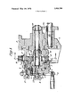
- FIG. 1 is a longitudinal sectional view of a feed mechanism according to the present invention.
- FIG. 2 is a cross sectional view taken along line 2-2 of FIG. 1.
- FIG. 1 illustrates a bed 1 with a sliding table 2 freely slidable on the bed adapted to support a workpiece (not shown).
- a manual feed handle 3 is fitted on the front of the bed 1.
- a movable clutch 6 arranged for manual-automatic switching is located on the in-
- a stationary clutch 23 opposite the movable clutch 6 is rotatably mounted to the shaft 5.
- the stationary clutch 23 and the movable clutch 6 are brought into intimate engagement with one another when the movable clutch 6 is shifted to the right, as viewed in FIG 1, by manipulation of the switch knob 11.
- a pinion 32 is formed at the rear of the stationary clutch 23. The pinion meshes with the rack piston 31 of an automatic feed cylinder.
- the stationary clutch 23 is rotated by the rack piston 31 and its associated pinion 32.
- Such rotation is transmitted via the movable clutch 6 to the handle shaft 5, and further from a gear 19 fitted to the end of the shaft 5 to a gear 20 at the end of a second shaft 21.
- the second shaft 21 is mounted parallel to the handle shaft Sand is connected to a feed screw (not shown) which effects the infeed of a grinder table, as is well known in the art.
- a transmitting disc 24 is freely mounted on the periphery of the stationary clutch 23.
- a rotatable cylinder 16 integrated with a worm wheel 17 is fitted around the disc 24.
- symmetrically cut recesses 25, 25 having contact surfaces 27, 27 and 28, 28 are located on part of the periphery of the disc 24.
- These recesses and the inside wall of the rotatable cylinder 16 enclose spaces 31, 31 which house transmitting members 13, 13 that extend from the boss 4 of the handle 3.
- the space 31, 31 house transmitting members 14, 14 that extend from a rotation-transmitting cylinder 7 fitted to the outside of the movable clutch 6 and in contact with the surfaces 28, 28 of the recesses 25, 25.
- the gaps 31, 31 between the transmitting members 13, 13 and 14, 14 are occupied by rollers 15, 15 held in wedged engagement between the inside wall of the rotatable cylinder 16 and cam surfaces 25a, 25a of the recesses.
- Compression springs 26, 26 projecting from the sides of the transmitting members 14, 14 hold the rollers in wedged engagement. Accordingly, when the rotatable cylinder 16 is turned clockwise, the rotation-transmitting disc 24 is also rotated clockwise by the wedged engagement of the rollers 15,, 15.
- the rollers 15, 15 are in predetermined spaced relationship with the surfaces 13a, 13a of the transmitting members 13, 13, and as explained more fully below, this relationship performs the fine feed of micron order when the transmitting members 13, 13 are held in contact with the surfaces 27, 27 of the recesses 25, 25.
- a contact plate 34 is fitted on the circumferential surface of the rotationtransmitting cylinder 7 outside the movable clutch 6. One part of the contact plate 34 adjoins the side surface of the movable clutch 6.
- a switching device 9 parallel to the handle shaft 5 is provided around the movable clutch 6, and the switching device engages a pressing piece 10.
- the pressing piece 10 presses the contact plate 34 on the side of the rotation-transmitting cylinder 7 to thereby solidly connect the rotation-transmitting cylinder 7 to the movable clutch 6.
- the pressing piece may solidly connect the handle 3 to the movable clutch 6 when the switching device 9 shifts the pressing piece to the left, as viewed in FIG. 1.
- a scale ring 8 is rotatably fitted on the outside of the boss 4 of the handle 3.
- a knob 12 is provided for locking the scale ring 8 to the handle.
- the worm wheel 17 integrated with the rotation cylinder 16 meshes with a worm 29 rotatably mounted in a bearing 30.
- a fine feed dial 18 is fixed at one end of the worm 29, and the fine feed device comprises the worm 29 and the worm wheel 17.
- the feed handle mechanism of the present invention functions in the following manner.
- the movable clutch 6 is first disengaged from the stationary clutch 23 through operation of the switching knob 11.
- the clutches 6, 23 are in their automatic condition of being in contact with one another.
- the pressing piece 10 is moved against the contact plate 34 to lock the rotation-transmitting cylinder 7 to the movable clutch 6.
- the transmitting members 13, 13 that extend from theboss 4 of the handle 3 bear against the contact surfaces 27, 27 of the rotation-transmitting disc 24.
- the rotation-transmitting disc 24 being rotatingly supported by the stationary clutch 23 is then turned clockwise, as viewed in FIG. 2.
- This rotation of the transmitting disc 24 causes the transmitting members 14, 14 bearing against the contact surfaces 28, 28 to rotate in the same direction.
- Rotation of the transmitting members l4, 14 is transmitted from the rotation-transmitting cylinder 7 via the movable clutch 6, the handle shaft 5, and the gears 19, 20 to the second shaft 21.
- Rotation of the second shaft 21 is transmitted to a feed screw (not shown) to thereby cause a coarse feed of the grinding table.
- the handle 3 is no longer capable of making the final micron order fine feed.
- the fine feed dial 18 is turned so as to rotate the worm 29.
- the worm wheel 17 in meshing engagement with the worm 29 is then turned in a clockwise direction (FIG. 2) to thereby rotate the cylinder 16 fixed to the worm wheel.
- Clockwise rotation of the cylinder 16 is transmitted to the disc 24 by wedged engagement of the rollers l5, between the inside wall of the rotatable cylinder 16 and the cam surfaces 25a, 25a of the recesses 25, 25.
- Rotation of the disc 24 is transmitted to the members 14, 14 hearing against the contact surfaces 28, 28.
- rotation of the members 14, 14 is transmitted from the cylinder 7 via the movable clutch 6, the handle shaft 5, and the gears 19, to the second shaft 21.
- the second shaft drives the feed screw to thereby cause a fine feed of the grinder table.
- the handle 3 is reversed to thereby turn the members 13, 13 in a counterclockwise direction.
- the surfaces l3a, 13a press against the rollers 15, 15 and overcome the wedged engagement of the rollers 15, 15 and the force of the compression springs 26, 26 to push the rollers toward the transmitting members 14, 14.
- counterclockwise rotation of the transmitting member 13 is transmitted via the rollers 15, 15 to the members 14, 14.
- the rotation-transmitting disc 24 turns in the same direction together with the transmitting members 14, 14.
- Rotation of the members 14 is transmitted from the rotation-transmitting cylinder 7 via the movable clutch 6, the handle shaft 5, and the gears 19, 20 to the second shaft 21.
- the second shaft operates the feed screw to thereby effect quick reversion of the grinder table.
- the pressing piece 10 and the contact plate 34 are separated from one another through operation of the switching device 9.
- the piece 10 is then pressed against the boss 4 of the handle 3, and the automatic-manual switch knob is operated to bring the tapered surfaces of the clutches 6, 23 into engagement with one another.
- the automatic feed cylinder can then be operated to move the rack piston 31 longitudinally to thereby produce an infeed of the grinder table.
- the present invention provides switching from manual coarse feed to fine feed without disconnecting the handle shaft from the fine feed device. Also,
- a feed mechanism for a machine tool comprising a shaft, a handle rotatably mounted about the shaft, a rotation-trans mitting plate rotatably mounted about the shaft, a hollow worm wheel rotatably mounted on the rotation-transmitting plate, a worm in engagement with the worm wheel, a knob connected to drive the worm, the rotation-transmitting plate having on its peripheral surface at least one recess provided with a cam surface thereon, a roller located between the inner wall of the hollow worm wheel and the cam surface of the recess forming two chambers between the inner wall of the worm wheel and the recess of the rotation-transmitting plate, a first member drivingly connected to the handle and received in one of the two chambers, a second member drivingly connected to the handle shaft and received in the other of the chambers, and spring means dis d between the second member and the roller to wedge t e roller between the inner wall of the worm wheel and the cam surface whereby the first member is adapted to transmit rotation of the handle in one direction
- a feed handle mechanism for a machine tool comprising a bed, a handle shaft rotatably mounted in the bed, a movable clutch slidably but non-rotatably mounted on the handle shaft and having a tapered surface at one end thereof, a handle rotatably mounted on the movable clutch, a stationary clutch rotatably mounted on the handle shaft and having a tapered surface at one end thereof associated with the tapered surface of the movable clutch and a gear at the other end of the stationary clutch, means for shifting the movable clutch axially relative to the handle shaft for selective engagement between the tapered surfaces, a hydraulic cylinder including a piston rod with a rack in engagement with the gear of the stationary clutch, a rotation-transmitting plate rotatably mounted on the stationary clutch, a hollow worm wheel rotatably mounted on the rotation-transmitting plate, a worm in engagement with the worm wheel, a knob connected to drive the worm, the rotation-transmitting plate having onits peripheral surface at least one recess provided with
Abstract
In the feed handle mechanism of a machine tool, a handle and a worm wheel are rotatably mounted on the handle shaft. A worm with an operating means at one end engages the worm wheel. The worm wheel is mutually rotatably fitted with a notched plate for transmitting the rotation. The space in the notch holds a rolling body which only transmits the rotation of the worm wheel to the rotation-transmitting plate. The notch also holds the transmitting member extending from the above mentioned handle and the transmitting member extending from the above mentioned handle shaft on both sides of the above mentioned rolling body.
Description
Unite States Patent Kobayashl 1451 May 30,1972
[54] FEED MECHANISM FOR MACHINE 2,621,540 12/1952 Rath ..74/626 TOOL 2,394,384 2/1946 Horstmann ..74/625 l, l [72] Inventor: Aklyoshl Kobayashi, Kariya, Japan 8 l 058 6/1931 Morgan 74/425 73 Assignee: Toyoda Koki Kabushiki Kaisha, Kariya, Primal? Examiner-William 1701393 Japan Assistant ExaminerWesley S. Ratliff, Jr. [22] Filed: Jan. 1971 Att0rneyC0nnolly & Hutz 1 App]. No.: 107,814 ABSTRACT In the feed handle mechanism of a machine tool, a handle and [30] Foreign A li ation Priorit D m a worm wheel are rotatably mounted on the handle shaft. A worm with an operating means at one end engages the worm Jan. 22, Japan e T e orm whe is ly rotatably fitted a 5 2 Us. CL H notched plate for transmitting the rotation. The space in the i 5 l Int Cl I notch holds a rolling body which only transmits the rotation of [58] Field of sea ch the worm wheel to the rotation-transmitting plate. The notch r 74/625 425's also holds the transmitting member extending from the above [56] R f mentioned handle and the transmitting member extending e erences cued from the above mentioned handle shaft on both sides of the UNITED STATES PATENTS above mentioned rolling body.
465,892 12/1891 Smith ..74/625 4 Claims, 2 Drawing Figures Patented May 30, 1972 3,665,786
2 Sheets-Sheet 1 FEED MECHANISM FOR MACHINE TOOL BACKGROUND OF THE INVENTION Most of the conventional feed handle mechanisms lack a fine feed device. Fine feed is usually executed on the hand feel" of a long experience operator working the feed. it is therefore practically impossible to make an extremely delicate infeed. Even with special mechanisms equipped with fine feed devices work efficiency has not been satisfactory because the handle shaft and the fine feed device must be disconnected for the purpose of switching from coarse feed to fine feed or quickly reverting the handle.
SUMMARY OF THE INVENTION The general object of the present invention is to provide a highly improved feed handle mechanism which eliminates the need for mechanical switching between coarse feed and fine feed.
Another object of the present invention is to provide simplified mechanical switching between fine and coarse feeds without disturbing the manual feed device.
In accordance with the present invention a feed handle mechanism for a machine tool comprises a shaft with a handle rotatably mounted to the shaft. A rotation-transmitting plate is rotatably mounted about the shaft, and a hollow worm wheel rotates about the rotation-transmitting plate. A worm in engagement with the worm wheel is driven by a knob connected thereto. The rotation-transmitting plate has at least one recess on its periphery with a cam surface in the recess. A roller is located between the inner wall of the hollow worm wheel and the cam surface of the recess, and the roller divides the recess into two chambers. A first member is drivingly connected to the handle and received in one of the two chambers, while a second member is drivingly connected to the handle shaft and received in the other of the chambers. A spring device disposed between the second member and the roller wedges the roller between the inner wall of the worm wheel and the cam surface. The first member is adapted to transmit rotation of the handle in one direction to the handle shaft through the rotation-transmitting plate and the second member. The roller is adapted to transmit rotation of the worm wheel in the one direction through rotation of the worm to the rotation-transmitting plate by wedged engagement thereof between the inner wall of the worm wheel and the cam surface of the recess. Also, the first member is adapted to transmit rotation of the handle in a direction opposite to the one direction to the handle shaft through the roller and the second member.
BRIEF DESCRIPTION OF THE DRAWING Novel features and advantages of the present invention in addition to those mentioned above will become apparent to those skilled in the art from a reading of the following detailed description in conjunction with the accompanying drawing wherein:
FIG. 1 is a longitudinal sectional view of a feed mechanism according to the present invention; and
FIG. 2 is a cross sectional view taken along line 2-2 of FIG. 1.
DETAILED DESCRIPTION OF THE INVENTION Referring in more particularity to the drawing, FIG. 1 illustrates a bed 1 with a sliding table 2 freely slidable on the bed adapted to support a workpiece (not shown). A manual feed handle 3 is fitted on the front of the bed 1. A movable clutch 6 arranged for manual-automatic switching is located on the in- A stationary clutch 23 opposite the movable clutch 6 is rotatably mounted to the shaft 5. The stationary clutch 23 and the movable clutch 6 are brought into intimate engagement with one another when the movable clutch 6 is shifted to the right, as viewed in FIG 1, by manipulation of the switch knob 11. A pinion 32 is formed at the rear of the stationary clutch 23. The pinion meshes with the rack piston 31 of an automatic feed cylinder. Accordingly, when the automatic feed cylinder is operated, the stationary clutch 23 is rotated by the rack piston 31 and its associated pinion 32. Such rotation is transmitted via the movable clutch 6 to the handle shaft 5, and further from a gear 19 fitted to the end of the shaft 5 to a gear 20 at the end of a second shaft 21. The second shaft 21 is mounted parallel to the handle shaft Sand is connected to a feed screw (not shown) which effects the infeed of a grinder table, as is well known in the art.
As shown best in FIG.. 2, a transmitting disc 24 is freely mounted on the periphery of the stationary clutch 23. A rotatable cylinder 16 integrated with a worm wheel 17 is fitted around the disc 24. symmetrically cut recesses 25, 25 having contact surfaces 27, 27 and 28, 28 are located on part of the periphery of the disc 24. These recesses and the inside wall of the rotatable cylinder 16 enclose spaces 31, 31 which house transmitting members 13, 13 that extend from the boss 4 of the handle 3. Moreover, the space 31, 31 house transmitting members 14, 14 that extend from a rotation-transmitting cylinder 7 fitted to the outside of the movable clutch 6 and in contact with the surfaces 28, 28 of the recesses 25, 25. The gaps 31, 31 between the transmitting members 13, 13 and 14, 14 are occupied by rollers 15, 15 held in wedged engagement between the inside wall of the rotatable cylinder 16 and cam surfaces 25a, 25a of the recesses. Compression springs 26, 26 projecting from the sides of the transmitting members 14, 14 hold the rollers in wedged engagement. Accordingly, when the rotatable cylinder 16 is turned clockwise, the rotation-transmitting disc 24 is also rotated clockwise by the wedged engagement of the rollers 15,, 15. The rollers 15, 15 are in predetermined spaced relationship with the surfaces 13a, 13a of the transmitting members 13, 13, and as explained more fully below, this relationship performs the fine feed of micron order when the transmitting members 13, 13 are held in contact with the surfaces 27, 27 of the recesses 25, 25. A contact plate 34 is fitted on the circumferential surface of the rotationtransmitting cylinder 7 outside the movable clutch 6. One part of the contact plate 34 adjoins the side surface of the movable clutch 6. A switching device 9 parallel to the handle shaft 5 is provided around the movable clutch 6, and the switching device engages a pressing piece 10. Under the pressure of the switching device 9 the pressing piece 10 presses the contact plate 34 on the side of the rotation-transmitting cylinder 7 to thereby solidly connect the rotation-transmitting cylinder 7 to the movable clutch 6. Alternatively, the pressing piece may solidly connect the handle 3 to the movable clutch 6 when the switching device 9 shifts the pressing piece to the left, as viewed in FIG. 1.
A scale ring 8 is rotatably fitted on the outside of the boss 4 of the handle 3. A knob 12 is provided for locking the scale ring 8 to the handle. Additionally, the worm wheel 17 integrated with the rotation cylinder 16 meshes with a worm 29 rotatably mounted in a bearing 30. A fine feed dial 18 is fixed at one end of the worm 29, and the fine feed device comprises the worm 29 and the worm wheel 17.
The feed handle mechanism of the present invention functions in the following manner. For the purpose of switching to manual operation, the movable clutch 6 is first disengaged from the stationary clutch 23 through operation of the switching knob 11. In the drawing, the clutches 6, 23 are in their automatic condition of being in contact with one another. The pressing piece 10 is moved against the contact plate 34 to lock the rotation-transmitting cylinder 7 to the movable clutch 6. In this condition, when the handle 3 is turned to the right, the transmitting members 13, 13 that extend from theboss 4 of the handle 3 bear against the contact surfaces 27, 27 of the rotation-transmitting disc 24. The rotation-transmitting disc 24 being rotatingly supported by the stationary clutch 23 is then turned clockwise, as viewed in FIG. 2. This rotation of the transmitting disc 24 causes the transmitting members 14, 14 bearing against the contact surfaces 28, 28 to rotate in the same direction. Rotation of the transmitting members l4, 14 is transmitted from the rotation-transmitting cylinder 7 via the movable clutch 6, the handle shaft 5, and the gears 19, 20 to the second shaft 21. Rotation of the second shaft 21 is transmitted to a feed screw (not shown) to thereby cause a coarse feed of the grinding table. As the grinding table moves forward and the workpiece is finished close to the final dimensions, the handle 3 is no longer capable of making the final micron order fine feed.
For the purpose of accomplishing the fine feed, the fine feed dial 18 is turned so as to rotate the worm 29. The worm wheel 17 in meshing engagement with the worm 29 is then turned in a clockwise direction (FIG. 2) to thereby rotate the cylinder 16 fixed to the worm wheel. Clockwise rotation of the cylinder 16 is transmitted to the disc 24 by wedged engagement of the rollers l5, between the inside wall of the rotatable cylinder 16 and the cam surfaces 25a, 25a of the recesses 25, 25. Rotation of the disc 24 is transmitted to the members 14, 14 hearing against the contact surfaces 28, 28. Also, rotation of the members 14, 14 is transmitted from the cylinder 7 via the movable clutch 6, the handle shaft 5, and the gears 19, to the second shaft 21. The second shaft drives the feed screw to thereby cause a fine feed of the grinder table.
For the purpose of quick reversion of the handle, the handle 3 is reversed to thereby turn the members 13, 13 in a counterclockwise direction. The surfaces l3a, 13a press against the rollers 15, 15 and overcome the wedged engagement of the rollers 15, 15 and the force of the compression springs 26, 26 to push the rollers toward the transmitting members 14, 14. Meanwhile, counterclockwise rotation of the transmitting member 13 is transmitted via the rollers 15, 15 to the members 14, 14. Thus, the rotation-transmitting disc 24 turns in the same direction together with the transmitting members 14, 14. Rotation of the members 14 is transmitted from the rotation-transmitting cylinder 7 via the movable clutch 6, the handle shaft 5, and the gears 19, 20 to the second shaft 21. The second shaft operates the feed screw to thereby effect quick reversion of the grinder table.
For the purpose of automatic operation, the pressing piece 10 and the contact plate 34 are separated from one another through operation of the switching device 9. The piece 10 is then pressed against the boss 4 of the handle 3, and the automatic-manual switch knob is operated to bring the tapered surfaces of the clutches 6, 23 into engagement with one another. The automatic feed cylinder can then be operated to move the rack piston 31 longitudinally to thereby produce an infeed of the grinder table.
As described above, the present invention provides switching from manual coarse feed to fine feed without disconnecting the handle shaft from the fine feed device. Also,
quick reversion of the handle is possible without such disconnection.
What is claimed is:
1. A feed mechanism for a machine tool comprising a shaft, a handle rotatably mounted about the shaft, a rotation-trans mitting plate rotatably mounted about the shaft, a hollow worm wheel rotatably mounted on the rotation-transmitting plate, a worm in engagement with the worm wheel, a knob connected to drive the worm, the rotation-transmitting plate having on its peripheral surface at least one recess provided with a cam surface thereon, a roller located between the inner wall of the hollow worm wheel and the cam surface of the recess forming two chambers between the inner wall of the worm wheel and the recess of the rotation-transmitting plate, a first member drivingly connected to the handle and received in one of the two chambers, a second member drivingly connected to the handle shaft and received in the other of the chambers, and spring means dis d between the second member and the roller to wedge t e roller between the inner wall of the worm wheel and the cam surface whereby the first member is adapted to transmit rotation of the handle in one direction to the handle shaft through the rotation-transmitting plate and the second member, the roller is adapted to transmit rotation of the worm wheel in the one direction by means of rotation of the worm to the rotation-transmitting plate by wedged engagement thereof between the inner wall of the worm wheel and the cam surface of the recess, and the first member is adapted to transmit rotation of the handle in a direction opposite to the one direction to the handle shaft through the roller and the second member.
2. A feed mechanism as in claim 1 wherein the first member is in predetermined spaced relationship with the roller when the first member transmits the rotation of the handle in the one direction to the handle shaft.
3. A feed handle mechanism for a machine tool comprising a bed, a handle shaft rotatably mounted in the bed, a movable clutch slidably but non-rotatably mounted on the handle shaft and having a tapered surface at one end thereof, a handle rotatably mounted on the movable clutch, a stationary clutch rotatably mounted on the handle shaft and having a tapered surface at one end thereof associated with the tapered surface of the movable clutch and a gear at the other end of the stationary clutch, means for shifting the movable clutch axially relative to the handle shaft for selective engagement between the tapered surfaces, a hydraulic cylinder including a piston rod with a rack in engagement with the gear of the stationary clutch, a rotation-transmitting plate rotatably mounted on the stationary clutch, a hollow worm wheel rotatably mounted on the rotation-transmitting plate, a worm in engagement with the worm wheel, a knob connected to drive the worm, the rotation-transmitting plate having onits peripheral surface at least one recess provided with a cam surface thereon, a roller located between the inner wall of the hollow worm wheel and the cam surface of the recess forming two chambers between the inner wall of the worm wheel and the recess of the rotation-transmitting plate, a first member drivingly connected to the handle and received in one of the two chambers, a cylindrical member rotatably mounted on the movable clutch, a second member drivingly connected to the cylindrical member and received in the other of the chambers, means for selectively clamping the cylindrical member to the movable clutch for rotation therewith, and spring means disposed between the second member and the roller to wedge the roller between the inner wall of the worm wheel and the cam surface whereby the first member is adapted to transmit rotation of the handle in one direction to the handle shaft through the rotation-transmitting plate and the second member, the roller is adapted to transmit rotation of the worm wheel in the one direction by means of rotation of the worm to the rotationtransmitting plate by wedged engagement thereof between the inner wall of the worm wheel and the cam surface of the recess, and the first member is adapted to transmit rotation of the handle in a direction opposite to the one direction to the handle shaft through the roller and the second member.
4. A feed handle mechanism as in claim 3 wherein the first member is in predetermined spaced relationship with the roller when the first member transmits the rotation of the handle in the one direction to the handle shaft.
Claims (4)
1. A feed mechanism for a machine tool comprising a shaft, a handle rotatably mounted about the shaft, a rotation-transmitting plate rotatably mounted about the shaft, a hollow worm wheel rotatably mounted on the rotation-transmitting plate, a worm in engagement with the worm wheel, a knob connected to drive the worm, the rotation-transmitting plate having on its peripheral surface at least one recess provided with a cam surface thereon, a roller located between the inner wall of the hollow worm wheel and the cam surface of the recess forming two chambers between the inner wall of the worm wheel and the recess of the rotationtransmitting plate, a first member drivingly connected to the handle and received in one of the two chambers, a second member drivingly connected to the handle shaft and received in the other of the chambers, and spring means disposed between the second member and the roller to wedge the roller between the inner wall of the worm wheel and the cam surface whereby the first member is adapted to transmit rotation of the handle in one direction to the handle shaft through the rotation-transmitting plate and the second member, the roller is adapted to transmit rotation of the worm wheel in the one direction by means of rotation of the worm to the rotation-transmitting plate by wedged engagement thereof between the inner wall of the worm wheel and the cam surface of the recess, and the first member is adapted to transmit rotation of the handle in a direction opposite to the one direction to the handle shaft through the roller and the second member.
2. A feed mechanism as in claim 1 wherein the first member is in predetermined spaced relationship with the roller when the first member transmits the rotation of the handle in the one direction to the handle shaft.
3. A feed handle mechanism for a machine tool comprising a bed, a handle shaft rotatably mounted in the bed, a movable clutch slidably but non-rotatably mounted on the handle shaft and having a tapered surface at one end thereof, a handle rotatably mounted on the movable clutch, a stationary clutch rotatably mounted on the handle shaft and having a tapered surface at one end thereof associated with the tapered surface of the movable clutch and a gear at the other end of the stationary clutch, means for shifting the movable clutch axially relative to the handle shaft for selective engagement between the tapered surfaces, a hydraulic cylinder including a piston rod with a rack in engagement with the gear of the stationary clutch, a rotation-transmitting plate rotatably mounted on the stationary clutch, a hollow worm wheel rotatably mounted on the rotation-transmitting plate, a worm in engagement with the worm wheel, a knob connected to drive the worm, the rotation-transmitting plate having on its peripheral surface at least one recess provided with a cam surface thereon, a roller located between the inner wall of the hollow worm wheel and the cam surface of the recess forming two chambers between the inner wall of the worm wheel and the recess of the rotation-transmitting plate, a first member drivingly connected to the handle and received in one of the two chambers, a cylindrical member rotatably mounted on the movable clutch, a second member drivingly connected to the cylindrical member and received in the other of the chambers, means for selectively clamping the cYlindrical member to the movable clutch for rotation therewith, and spring means disposed between the second member and the roller to wedge the roller between the inner wall of the worm wheel and the cam surface whereby the first member is adapted to transmit rotation of the handle in one direction to the handle shaft through the rotation-transmitting plate and the second member, the roller is adapted to transmit rotation of the worm wheel in the one direction by means of rotation of the worm to the rotation-transmitting plate by wedged engagement thereof between the inner wall of the worm wheel and the cam surface of the recess, and the first member is adapted to transmit rotation of the handle in a direction opposite to the one direction to the handle shaft through the roller and the second member.
4. A feed handle mechanism as in claim 3 wherein the first member is in predetermined spaced relationship with the roller when the first member transmits the rotation of the handle in the one direction to the handle shaft.
Applications Claiming Priority (1)
| Application Number | Priority Date | Filing Date | Title |
|---|---|---|---|
| JP1970006735U JPS4843667Y1 (en) | 1970-01-22 | 1970-01-22 |
Publications (1)
| Publication Number | Publication Date |
|---|---|
| US3665786A true US3665786A (en) | 1972-05-30 |
Family
ID=11646471
Family Applications (1)
| Application Number | Title | Priority Date | Filing Date |
|---|---|---|---|
| US107814A Expired - Lifetime US3665786A (en) | 1970-01-22 | 1971-01-19 | Feed mechanism for machine tool |
Country Status (4)
| Country | Link |
|---|---|
| US (1) | US3665786A (en) |
| JP (1) | JPS4843667Y1 (en) |
| DE (1) | DE2102994C3 (en) |
| FR (1) | FR2077270B1 (en) |
Cited By (6)
| Publication number | Priority date | Publication date | Assignee | Title |
|---|---|---|---|---|
| US4261218A (en) * | 1978-12-26 | 1981-04-14 | Eagan Joseph A Sen | Speed reducer adjustment means |
| US4813303A (en) * | 1984-08-31 | 1989-03-21 | Mandreles, Inc. | Power drive speed reducer |
| US20080163712A1 (en) * | 2005-09-28 | 2008-07-10 | Hans-Juergen Oberle | Transmission Drive Unit With a Zero Axial Backlash Bearing Fastening, In Particular For Adjusting a Movable Part in a Motor Vehicle |
| CN104786148A (en) * | 2015-05-14 | 2015-07-22 | 吴江市新科缝制设备有限公司 | Adjusting rod device of centerless grinding machine |
| US20170350182A1 (en) * | 2015-02-23 | 2017-12-07 | Mabuchi Motor Co., Ltd. | Reverse rotation prevention mechanism and motor with reducer |
| CN109352033A (en) * | 2018-10-31 | 2019-02-19 | 高朝仲 | The rotary monolever rocking bar feed system of bending and its drilling machine |
Families Citing this family (1)
| Publication number | Priority date | Publication date | Assignee | Title |
|---|---|---|---|---|
| DE4314391C2 (en) * | 1993-04-30 | 1996-05-23 | Augustin & Bamberg Gmbh | CNC retrofit kit for conventional lathes |
Citations (4)
| Publication number | Priority date | Publication date | Assignee | Title |
|---|---|---|---|---|
| US465892A (en) * | 1891-12-29 | Feed connection for drill-presses and other machines | ||
| US1811058A (en) * | 1929-11-25 | 1931-06-23 | Timken Axle Co Detroit | Worm drive axle |
| US2394384A (en) * | 1941-07-21 | 1946-02-05 | Sperry Gyroscope Co Ltd | Dual control system |
| US2621540A (en) * | 1949-09-22 | 1952-12-16 | Hupp Corp | Combined manual and automatic window regulator |
Family Cites Families (2)
| Publication number | Priority date | Publication date | Assignee | Title |
|---|---|---|---|---|
| GB652547A (en) * | 1948-08-25 | 1951-04-25 | H W Ward And Company Ltd | Improvements relating to lathes |
| FR1108050A (en) * | 1954-06-30 | 1956-01-09 | G S P Guillemin Sergot Pegard | Control box for moving a moving part, applicable in particular to machine tools |
-
1970
- 1970-01-22 JP JP1970006735U patent/JPS4843667Y1/ja not_active Expired
-
1971
- 1971-01-19 US US107814A patent/US3665786A/en not_active Expired - Lifetime
- 1971-01-20 FR FR7101724A patent/FR2077270B1/fr not_active Expired
- 1971-01-22 DE DE2102994A patent/DE2102994C3/en not_active Expired
Patent Citations (4)
| Publication number | Priority date | Publication date | Assignee | Title |
|---|---|---|---|---|
| US465892A (en) * | 1891-12-29 | Feed connection for drill-presses and other machines | ||
| US1811058A (en) * | 1929-11-25 | 1931-06-23 | Timken Axle Co Detroit | Worm drive axle |
| US2394384A (en) * | 1941-07-21 | 1946-02-05 | Sperry Gyroscope Co Ltd | Dual control system |
| US2621540A (en) * | 1949-09-22 | 1952-12-16 | Hupp Corp | Combined manual and automatic window regulator |
Cited By (10)
| Publication number | Priority date | Publication date | Assignee | Title |
|---|---|---|---|---|
| US4261218A (en) * | 1978-12-26 | 1981-04-14 | Eagan Joseph A Sen | Speed reducer adjustment means |
| US4813303A (en) * | 1984-08-31 | 1989-03-21 | Mandreles, Inc. | Power drive speed reducer |
| US20080163712A1 (en) * | 2005-09-28 | 2008-07-10 | Hans-Juergen Oberle | Transmission Drive Unit With a Zero Axial Backlash Bearing Fastening, In Particular For Adjusting a Movable Part in a Motor Vehicle |
| US8365630B2 (en) * | 2005-09-28 | 2013-02-05 | Robert Bosch Gmbh | Transmission drive unit with a zero axial backlash bearing fastening, in particular for adjusting a movable part in a motor vehicle |
| US20170350182A1 (en) * | 2015-02-23 | 2017-12-07 | Mabuchi Motor Co., Ltd. | Reverse rotation prevention mechanism and motor with reducer |
| US10731398B2 (en) * | 2015-02-23 | 2020-08-04 | Mabuchi Motor Co., Ltd. | Reverse rotation prevention mechanism and motor with reducer |
| CN104786148A (en) * | 2015-05-14 | 2015-07-22 | 吴江市新科缝制设备有限公司 | Adjusting rod device of centerless grinding machine |
| CN104786148B (en) * | 2015-05-14 | 2017-05-31 | 吴江市新科缝制设备有限公司 | A kind of regulation lever apparatus of centerless grinder |
| CN109352033A (en) * | 2018-10-31 | 2019-02-19 | 高朝仲 | The rotary monolever rocking bar feed system of bending and its drilling machine |
| CN109352033B (en) * | 2018-10-31 | 2020-07-28 | 高朝仲 | Bending rotation type single-handle rocker feeding system and drilling machine thereof |
Also Published As
| Publication number | Publication date |
|---|---|
| DE2102994A1 (en) | 1971-07-29 |
| JPS4843667Y1 (en) | 1973-12-17 |
| FR2077270A1 (en) | 1971-10-22 |
| DE2102994B2 (en) | 1974-06-20 |
| FR2077270B1 (en) | 1974-04-26 |
| DE2102994C3 (en) | 1975-01-30 |
Similar Documents
| Publication | Publication Date | Title |
|---|---|---|
| US3665786A (en) | Feed mechanism for machine tool | |
| US3876014A (en) | Rotary hammer with rotation stop control trigger | |
| US3337996A (en) | Thread grinding machine | |
| US1696178A (en) | Transmission gearing | |
| US2950626A (en) | Combination portable electric drill and screwdriver | |
| US2321442A (en) | Collapsible antifriction nut | |
| US3844068A (en) | Cam grinding machine | |
| US3707889A (en) | Power control apparatus | |
| US3849940A (en) | Honing machine | |
| US2914153A (en) | Adjustable dial | |
| GB1096023A (en) | Printing machines | |
| US2453600A (en) | Indexing mechanism | |
| US3791084A (en) | Grinding machine with wheel dress compensating apparatus | |
| US2717522A (en) | Play compensating device for the gear wheels of a kinematic chain | |
| US3124998A (en) | raehrs | |
| US3665653A (en) | Feed mechanism for machine tool | |
| US3267812A (en) | Flexible band drive | |
| US3137103A (en) | Grinder | |
| US3798722A (en) | Coupling assembly | |
| US2002967A (en) | Grinding apparatus | |
| US3380198A (en) | Parallel plane honing equipment | |
| US2010361A (en) | Grinding machine | |
| US2513694A (en) | Thread grinding machine | |
| US2641876A (en) | Precision grinding machine | |
| US2399397A (en) | Marking or embossing machine |