US3661474A - Liquid booster device - Google Patents
Liquid booster device Download PDFInfo
- Publication number
- US3661474A US3661474A US10279A US3661474DA US3661474A US 3661474 A US3661474 A US 3661474A US 10279 A US10279 A US 10279A US 3661474D A US3661474D A US 3661474DA US 3661474 A US3661474 A US 3661474A
- Authority
- US
- United States
- Prior art keywords
- impeller
- liquid
- shaft
- pump
- inlet
- Prior art date
- Legal status (The legal status is an assumption and is not a legal conclusion. Google has not performed a legal analysis and makes no representation as to the accuracy of the status listed.)
- Expired - Lifetime
Links
- 239000007788 liquid Substances 0.000 title claims abstract description 78
- 230000008878 coupling Effects 0.000 claims description 5
- 238000010168 coupling process Methods 0.000 claims description 5
- 238000005859 coupling reaction Methods 0.000 claims description 5
- 238000009835 boiling Methods 0.000 abstract description 7
- 238000010276 construction Methods 0.000 description 6
- 125000006850 spacer group Chemical group 0.000 description 4
- 238000007789 sealing Methods 0.000 description 3
- 244000186140 Asperula odorata Species 0.000 description 2
- 235000008526 Galium odoratum Nutrition 0.000 description 2
- 239000011435 rock Substances 0.000 description 2
- OKTJSMMVPCPJKN-UHFFFAOYSA-N Carbon Chemical compound [C] OKTJSMMVPCPJKN-UHFFFAOYSA-N 0.000 description 1
- 244000025221 Humulus lupulus Species 0.000 description 1
- 235000008694 Humulus lupulus Nutrition 0.000 description 1
- CYTYCFOTNPOANT-UHFFFAOYSA-N Perchloroethylene Chemical compound ClC(Cl)=C(Cl)Cl CYTYCFOTNPOANT-UHFFFAOYSA-N 0.000 description 1
- 241000277331 Salmonidae Species 0.000 description 1
- 229910052799 carbon Inorganic materials 0.000 description 1
- 230000003028 elevating effect Effects 0.000 description 1
- 210000004907 gland Anatomy 0.000 description 1
- 238000005461 lubrication Methods 0.000 description 1
- 239000000463 material Substances 0.000 description 1
- 238000010791 quenching Methods 0.000 description 1
- 230000003252 repetitive effect Effects 0.000 description 1
- 238000009834 vaporization Methods 0.000 description 1
- 230000008016 vaporization Effects 0.000 description 1
Images


Classifications
-
- F—MECHANICAL ENGINEERING; LIGHTING; HEATING; WEAPONS; BLASTING
- F04—POSITIVE - DISPLACEMENT MACHINES FOR LIQUIDS; PUMPS FOR LIQUIDS OR ELASTIC FLUIDS
- F04D—NON-POSITIVE-DISPLACEMENT PUMPS
- F04D13/00—Pumping installations or systems
- F04D13/12—Combinations of two or more pumps
-
- F—MECHANICAL ENGINEERING; LIGHTING; HEATING; WEAPONS; BLASTING
- F04—POSITIVE - DISPLACEMENT MACHINES FOR LIQUIDS; PUMPS FOR LIQUIDS OR ELASTIC FLUIDS
- F04D—NON-POSITIVE-DISPLACEMENT PUMPS
- F04D5/00—Pumps with circumferential or transverse flow
- F04D5/002—Regenerative pumps
-
- F—MECHANICAL ENGINEERING; LIGHTING; HEATING; WEAPONS; BLASTING
- F04—POSITIVE - DISPLACEMENT MACHINES FOR LIQUIDS; PUMPS FOR LIQUIDS OR ELASTIC FLUIDS
- F04D—NON-POSITIVE-DISPLACEMENT PUMPS
- F04D5/00—Pumps with circumferential or transverse flow
- F04D5/002—Regenerative pumps
- F04D5/003—Regenerative pumps of multistage type
- F04D5/006—Regenerative pumps of multistage type the stages being axially offset
-
- F—MECHANICAL ENGINEERING; LIGHTING; HEATING; WEAPONS; BLASTING
- F04—POSITIVE - DISPLACEMENT MACHINES FOR LIQUIDS; PUMPS FOR LIQUIDS OR ELASTIC FLUIDS
- F04D—NON-POSITIVE-DISPLACEMENT PUMPS
- F04D7/00—Pumps adapted for handling specific fluids, e.g. by selection of specific materials for pumps or pump parts
- F04D7/02—Pumps adapted for handling specific fluids, e.g. by selection of specific materials for pumps or pump parts of centrifugal type
- F04D7/06—Pumps adapted for handling specific fluids, e.g. by selection of specific materials for pumps or pump parts of centrifugal type the fluids being hot or corrosive, e.g. liquid metals
-
- F—MECHANICAL ENGINEERING; LIGHTING; HEATING; WEAPONS; BLASTING
- F04—POSITIVE - DISPLACEMENT MACHINES FOR LIQUIDS; PUMPS FOR LIQUIDS OR ELASTIC FLUIDS
- F04D—NON-POSITIVE-DISPLACEMENT PUMPS
- F04D9/00—Priming; Preventing vapour lock
- F04D9/04—Priming; Preventing vapour lock using priming pumps; using booster pumps to prevent vapour-lock
-
- Y—GENERAL TAGGING OF NEW TECHNOLOGICAL DEVELOPMENTS; GENERAL TAGGING OF CROSS-SECTIONAL TECHNOLOGIES SPANNING OVER SEVERAL SECTIONS OF THE IPC; TECHNICAL SUBJECTS COVERED BY FORMER USPC CROSS-REFERENCE ART COLLECTIONS [XRACs] AND DIGESTS
- Y10—TECHNICAL SUBJECTS COVERED BY FORMER USPC
- Y10S—TECHNICAL SUBJECTS COVERED BY FORMER USPC CROSS-REFERENCE ART COLLECTIONS [XRACs] AND DIGESTS
- Y10S415/00—Rotary kinetic fluid motors or pumps
- Y10S415/901—Drilled well-type pump
Definitions
- ABSTRACT [52] US. Cl ..415/143, 415/501 A li id b t device integrally formed with a turbine pump [51] Int. Cl ..F04d 1/00, F04d l/O6 f d li i a liquid at or near boiling point upwardly f a [58] Fleld 0 Search ..415/143, 203, 501 quid reservoir to the pump inIeL
- a irc r flange is formed at the main pumps inlet for 1,004,015 9/ l 91 l Goodner... ..415/501 mounting the combined turbine pump liquid booster device 2, 3/1959 Roth /1 at the top of the liquid reservoir such that the booster impeller 3 ,247,797 4/ l 966 Sieghartner. 415/143 i5 ubmerged in the liquid,
- This invention relates to pumps designed to handle liquids at or near the boiling point.
- Liquids at or near the boiling point have significant vapor pressure which tends to oppose the external forces that move a liquid into the pump suction. Thus, it is necessary to apply an external force on the liquid greater than its opposing vapor pressure.
- One way of providing this external pressure is by elevating the storage tanks above the level of the pump.
- This invention is intended to satisfy the need for a liquid booster device to raise a liquid at or near the boiling point from a storage tank to a pump at the required pressure without changing the liquid to a vapor and to operate in a consistent and dependable manner.
- This invention is directed to a liquid booster device for raising a liquid at or near boiling point from a storage tank to a main pump, where the main pump is any conventional liquid pump capable of developing the higher heads required to deliver liquids for processing.
- the liquid booster device is integrally formed with the main pump, and comprises a tubular casing extending from the main pumps inlet and one or more booster impeller stages having impellers rotatably mounted on a shaft extension of the main pumps shaft.
- a mounting flange is provided between the pumps inlet and the tubular casing for mounting the combined unit of the main pump and liquid booster device in such a manner that the liquid booster device will extend downwardly into the storage tank.
- the required number of booster impellers spaced at selected intervals along the shaft extension to raise the liquid smoothly up the tubular casing is determined by volatility of the liquid and the depth of the storage tank.
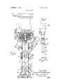
- FIG. 1 is a side elevational view of the First Embodiment of this invention.
- FIG. 2 is a side elevational view of the Second Embodiment of this invention.
- FIG. 3 is a sectional view taken along the line 3-3 of FIG.
- FIG. 4 is a partial sectional view of the Second Embodiment of this invention.
- FIG. 5 is a partial sectional view of the Third Embodiment of this invention.
- FIG. 6 is a partial sectional view of the Fourth Embodiment of this invention.
- FIG. 7 is a sectional view taken along the line 7-7 of FIG. 6.
- FIGS. 1 and 3 the first embodiment of this invention is illustrated and includes a one-stage turbine pump having a casing 10 with an inboard head 12 and a case head 14, and a shaft 16.
- the one-stage turbine pump of FIGS. 1 and 3 is shown to illustrate one use of the present invention and forms no part of this invention.
- a shaft sleeve 18 surrounds the shaft 16 and at 20 abuts the inboard end of the impeller 19. The opposite end of the sleeve abuts a shoulder 24 on the shaft 16.
- a stuffing box 26 and a gland 28 are positioned about shaft 16, and are fastened to inboard head 12.
- a carbon stationary seat is provided at 30 and a quench bushing is provided at 32.
- An enlarged diameter portion 34 of shaft 16 is joumalled for rotation in an inboard bearing 36.
- the outer housing cap 42 holds the shaft-impeller assembly rigidly in an axial position by clamping the outer race through this snap ring against the end of the frame 40.
- a cap seal 44 is disposed about the shaft 16 within the cap 42.
- a lubrication fitting is provided at 46.
- An annular stationary bushing 48 is disposed within the case 10 and surrounds an impeller spacer 50(The impeller spacer 50 abuts between the outer end of hub 54 of impeller 19 and the inner end of shaft coupler 56.
- the turbine impeller 19 and impeller spacer 50 are fixed by Woodrufl keys 58 or splines to rotate with the shaft 16.
- the impeller 19 rotates between. wear rings 60 which cooperate with the opposite sides of the impeller 19 to form sealing surfaces 62.
- the impeller 19 has vanes or blades 64 opening from the opposite sides and peripherally from the impeller 19 and are operable in channel 66 where the liquid is discharged through pump outlet 68.
- case head 14 is provided with a circular mounting flange 70 with spaced mounting apertures 72 which may be readily fastened to a support in a storage tank or pipe such that the liquid booster device 74 extends downwardly and its lower portion submerged in the liquid stored in the tank.
- the motor 76 which, for example, could be a standard Nema flange mounted type, is flexibly connected to the pump shaft 16 by means of a standard flexible coupling.
- the liquid booster device 74 of this invention is housed in a generally tubular casing 84 constructed by joining a plurality of column sections 86 together by means of clamp ring 88, snap ring 90 combination and clamp bolts 92, and by joining a bowl section 94 to the lowermost column section 86 by means of bolts 96.
- Bowl section 94 is made up of upper and lower members 98, held together by clamp bolts 102.
- the uppermost column section 86 is secured to the mounting flange 70 by means of threaded bolts 104.
- bearing support members 106 having a tubular center portion 108 interconnected to the outer tubular portion 110 by a plurality of radial ribs 112. Mounted in the tubular. center portion 108 of each bearing support member 106 is a bushing 114 positioned at spaced intervals along shaft extension 116 to prevent shaft whip.
- An impeller 118 which is widely separated from the turbine pump inlet as depicted in FIG. 3, is mounted at the lowermost end of shaft extension 116 by means of lock nut 120.
- the hub 122 of impeller 118 rotates in bushing 124.
- Bowl section 94 has an inlet 128 which opens into the suction inlet 126 of the centrifugal impeller 118.
- the impeller 118 can be any of a number of known impeller designs that will ease the liquid into motion and drive it up to the turbine inlet 131.
- the criteria in selecting the impeller 118 is that it should have a low disturbance on the liquid at or near boiling point (i.e. low pressure creating characteristics) so that the liquid will not be vaporized prior to entering the tur bine inlet 131.
- a suitable impeller design which could be used for impeller 118 is disclosed in U.S. Pat. No. 2,875,698 to Leo C. Roth, which is assigned to the same assignee as this invention.
- FIGS. 1 and 2 The embodiment of FIGS. 1 and 2 is mounted to the top of a liquid storage tank such that the lower end of liquid booster device 74 is submerged in the liquid. It is noted that it is not essential that the liquid booster 74 be mounted in a vertical orientation.
- the liquid enters the suction inlet 126 of impeller 118, where the liquid is smoothly stirred into motion and pushed up tubular casing84 to the turbine stage constituted by turbine impeller 19 and is discharged through outlet 68.
- FIGS. 2 and 4 depicts the invention combined with a two-stage turbine pump having a casing, generally designated by the reference numeral 150.
- Turbine impellers 152, 154 are fixed by Woodrufi keys or splines 156 and 158, respectively, to rotate with shaft 160.
- the impeller 152 rotates between outer and inner liners 162, 164 and the impeller 154 rotates between outer and inner liners 166, 168.
- the liners 162, 164 cooperate with the opposite sides of the impeller 152 to form sealing surfaces 170
- liners 166, 168 cooperate with the opposite sides of impeller 154 to form sealing surfaces 172.
- Impeller 152 has vanes or blades 180 in a liquid channel 182 opening from the opposite sides and peripherally from im 7 peller 152.
- the casing 150 has an outboard cover 186 secured to casing 150 by cap screws 188. Integrally formed with outboard cover 186 is a mounting flange 190 having mounting holes 192.
- the inboard end of the two-stage turbine pump of FIGS. 2 and 4 is identical in construction to the one-stage turbine pump of FIGS. 1 and 3, and consequently, a description and showing of the inboard end has been omitted.
- the two-stage turbine pump of FIGS. 2 and 4 could use the same coupling arrangement between the shaft 160 and the shaft of a motor 194 (FIG. 2) as is disclosed in the FIGS. 1 and 3 embodiment.
- a shaft sleeve 196 surrounds the shaft 160 and abuts the inboard end of hub 178 of impeller 154.
- An annular stationary bushing 200 surrounds the hub 174 of impeller 154 and is disposed within the outer liner 166 for impeller 154.
- the bushing 200 has an external annular flange 202, which abuts endwise in an inboard direction against an internal annular flange of the liner 166.
- Bushing 200 cooperates with a floating ring 201 to seal off the turbine high pressure liquid from the low pressure stage, as fully disclosed in US. Pat. No. 3,154,020 to Leonard J. Sieghartner, which is assigned to the same assignee as this invention.
- the liquid booster device 74' shown in FIGS. 2 and 4 is identical in construction and operation to the liquid booster device 74 of FIGS, 1 and 3, and like parts in FIGS. 2 and 4 are identified by prime numbers.
- the tubular casing 84' is supported downwardly from mounting flange 190 to form an integral unit with the two-stage turbine pump.
- the liquid enters the suction inlet 126 of impeller 118' where the liquid is smoothly stirred into motion and pushed up tubular casing 84 to the first turbine stage constituted by impeller 152.
- the liquid passes to the second stage constituted by impeller 154 and exits through outlet 210.
- FIG. 5 The third embodiment illustrating this invention is depicted in FIG. 5, which includes a centrifugal-turbine pump having a casing 250 and a shaft 252.
- a turbine impeller 254 is fixed by a Woodrufi' key 256 to shaft 252 and rotates between wear rings 258, which A shaft sleeve 262 surrounds the shaft 252 and abuts the inboard end of impeller 254. Abutting the outboard end of impeller 254 is the hub 266 of centrifugal impeller 268, which is fixed to shaft 252 by Woodruff key 270.
- the centrifugal impeller 268 rotates within the channel 274 and the hub 269 rotates in bushing 276.
- An annular stationary bushing 272 surrounds the hub 266 of impeller 268.
- a case head 278 is attached to the main casing 250 and has an inlet 280 which opens into the suction inlet 282 of the centrifugal impeller 268.
- case head 278 is provided with a circular flange 284 which is fastened by bolts 286 to a circular mounting plate 288, having spaced mounting apertures 290 for mounting to a support at the top of liquid storage tank or reservoir in such a manner that the lower portion of liquid booster device 292 would be submerged in the liquid stored therein.
- the liquid booster device 292 differs in construction from the liquid booster device 274 of the First and Second Embodiments by having an additional booster stage.
- the housing for liquid booster device is similarly constructed by joining together a plurality of column sections 294, bearing support members 296 and two bowl sections 298.
- the bearing support members 296 are sandwiched between adjacent column sections 294 and secured together by means of the combination clamp ring 298, snap ring 300 and clamp bolts 301.
- the bowl sections which house the pair of booster impellers 302 and 304, have two half members 306, 308 held together by clamp bolts 310, and are attached to the adjacent clamp rings 298 by bolts 312. I
- the bearing support members 296 comprise a' tubular center portion 314 interconnected to the outer tubular portion 316 by a plurality of radial ribs 318.
- a bushing 320 positioned at spaced intervals along shaft extension 322 to prevent shaft whip.
- the upper impeller 302 is mounted on shaft extension 322 at its approximate mid-length and is fixed thereto by set screw 324.
- the lower impeller 304 is secured on the lower end of shaft extension 322 by lock nut 326.
- the upper end of shaft extension 322 is secured to the lower end of shaft 252 and thus rotates therewith.
- upper and lower impellers 302, 304' are likewise driven and their respective hubs 328, 330 rotate in bushings 322, 334, respectively.
- the upper and lower impellers 302, 304 could be any of a number of known impeller designs that will ease the liquid into motion and drive it up to the centrifugal impeller inlet 282, for example, see Roth US. Pat. No.- 2,875,698.
- the criteria for designing such an impeller is that it hm low pressure creating characteristics to avoid vaporin'ng the liquid being pumped.
- the impellers 268, 302 and 304 are widely separated and the spacing between impellers 268, 302 and 304 is determined by the volatility of the liquid being handled, for it the vaporization of the liquid be avoided.
- liquid enters the suction inlet 336 of lower booster impeller 304, where it is delivered up to suction inlet 338 of upper booster impeller 302, where it is boosted up to suction inlet 282 of centrifugal impeller 268.
- the liquid then passes from the centrifugal stage to the turbine stage constituted by Turbine impeller 254 and is discharged through outlet 264.
- FOURTH EMBODIMENT is essenfial thatblades 374 opening from the opposite sides which operate within channel 376.
- the impeller 356 has vanes or blades 378 opening from the opposite sides which operate within channel 380.
- the inboard end of the two stage turbine pump of FIG. 6 is identical in construction to the one-stage turbine pump disclosed in the First Embodiment (FIGS. 1 and 3) and consequently, the details of the inboard end have been omitted.
- a shaft sleeve 382 surrounds the shaft 352 and abuts the inboard end of hub 372 of impeller 356. Abutting the outboard end of impeller 354 is hub 384 of centrifugal impeller 386, which is fixed to shaft 352 by Woodruff key 388. The centrifugal impeller 386 rotates within the channel 390 and hub 392 rotates in bushing 394. An annular stationary bushing 396 surrounds the hub 384 of impeller 386.
- a case head 400 is attached to the main casing 350 and has an inlet 402 which opens into the suction inlet 404 of the centrifugal impeller 386.
- the lower end of case head 400 is provided with a circular flange 406 which is fastened by bolts 408 to a circular mounting plate 410, having spaced mounting apertures 412 for mounting to a support at the top of a liquid storage tank or liquid reservoir.
- liquid booster device 414 Extending downwardly from mounting plate 410 is a liquid booster device 414, which is identical in construction and operation as liquid booster device 74 depicted in the FIGS. 1 and 3 embodiment. Consequently, a description of its construction would be repetitive and like parts will be identified by using double prime numbers.
- impeller 118 like impellers l 18 and 118, be of a design which will ease the liquid smoothly into motion and deliver it up the tubular casing 84" to the outside integrally mounted turbine pump.
- FIG. 7 depicts a suitable design for the casing for impeller 118", namely a difiuser type, that can be used in practicing this invention.
- a suitable design for the casing for impeller 118 namely a difiuser type, that can be used in practicing this invention.
- circular type or volute type casings could be used.
- a liquid booster device for delivering a liquid upwardly from a liquid reservoir to the inlet of a turbine pump, comprising a shaft extension coupled to the shaft of a turbine pump, an impeller having low pressure creating characteristics fixedly mounted on said shaft extension in a widely separated relation with said turbine pump inlet, a tubular casing disposed about said shaft extension and said impeller and having its upper open end secured to the inlet of the turbine pump to form an integral housing therewith, and means for mounting said integral housing in an upright orientation such that said tubular casing extends downwardly into the liquid reservoir, where said tubular casing includes at least one bearing support member for rotatably supporting said shaft extension disposed between said impeller and the coupling between said shaft extension and the shaft for the turbine pump.
- tubular easing further includes a bowl section surrounding the periphery of said impeller and having a bushing for rotatably supporting the hub of said impeller.
Landscapes
- Engineering & Computer Science (AREA)
- Mechanical Engineering (AREA)
- General Engineering & Computer Science (AREA)
- Structures Of Non-Positive Displacement Pumps (AREA)
Applications Claiming Priority (1)
| Application Number | Priority Date | Filing Date | Title |
|---|---|---|---|
| US1027970A | 1970-02-10 | 1970-02-10 |
Publications (1)
| Publication Number | Publication Date |
|---|---|
| US3661474A true US3661474A (en) | 1972-05-09 |
Family
ID=21745002
Family Applications (1)
| Application Number | Title | Priority Date | Filing Date |
|---|---|---|---|
| US10279A Expired - Lifetime US3661474A (en) | 1970-02-10 | 1970-02-10 | Liquid booster device |
Country Status (6)
| Country | Link |
|---|---|
| US (1) | US3661474A (de) |
| BE (1) | BE762300A (de) |
| CA (1) | CA929793A (de) |
| CH (1) | CH531650A (de) |
| DE (1) | DE2106323B2 (de) |
| GB (1) | GB1323546A (de) |
Cited By (16)
| Publication number | Priority date | Publication date | Assignee | Title |
|---|---|---|---|---|
| US4299536A (en) * | 1979-08-09 | 1981-11-10 | Roy E. Roth Company | Multi-stage pumps |
| EP0040569A1 (de) * | 1980-05-16 | 1981-11-25 | SIHI Pompes Société Anonyme dite | Selbstansaugende Seitenkanalpumpe zur Förderung von Flüssiggas aus einem unterirdischen Tank |
| US5076757A (en) * | 1981-01-29 | 1991-12-31 | Vaughan Co., Inc. | High head centrifugal slicing slurry pump |
| US5295784A (en) * | 1991-08-24 | 1994-03-22 | Durr Dental Gmbh & Co. Kg | Suction device, especially for use in dentistry |
| US20060024174A1 (en) * | 2004-07-28 | 2006-02-02 | Welch C E | Pump |
| RU2332591C2 (ru) * | 2006-07-27 | 2008-08-27 | Открытое акционерное общество "Копейский машиностроительный завод" | Центробежный насос |
| EP2505843A1 (de) * | 2011-03-29 | 2012-10-03 | Grundfos Management a/s | Kreiselpumpenanordnung |
| RU2468256C1 (ru) * | 2011-11-21 | 2012-11-27 | Закрытое Акционерное Общество Научно-Производственное Объединение "Тэн" | Универсальная транспортная система вертикального нефтяного электронасосного агрегата |
| RU2468255C1 (ru) * | 2011-11-21 | 2012-11-27 | Закрытое Акционерное Общество Научно-Производственное Объединение "Тэн" | Вертикальный нефтяной электронасосный агрегат (варианты) и валопровод вертикального электронасосного агрегата (варианты) |
| RU2470188C1 (ru) * | 2011-11-21 | 2012-12-20 | Закрытое Акционерное Общество Научно-Производственное Объединение "Тэн" | Бустер вертикального нефтяного электронасосного агрегата |
| RU2472044C1 (ru) * | 2011-11-21 | 2013-01-10 | Закрытое Акционерное Общество Научно-Производственное Объединение "Тэн" | Комплексный гидравлический канал вертикального нефтяного электронасосного агрегата |
| RU2472039C1 (ru) * | 2011-11-21 | 2013-01-10 | Закрытое Акционерное Общество Научно-Производственное Объединение "Тэн" | Конструктивный ряд вертикальных нефтяных электронасосных агрегатов |
| RU2521527C1 (ru) * | 2013-02-11 | 2014-06-27 | Федеральное государственное унитарное предприятие "Научно-производственное предприятие "Исток" (ФГУП "НПП "Исток") | Центробежно-вихревой двухступенчатый насос |
| CN106151110A (zh) * | 2016-08-18 | 2016-11-23 | 武汉船用机械有限责任公司 | 一种连接支撑装置 |
| RU182695U1 (ru) * | 2017-07-24 | 2018-08-28 | Открытое акционерное общество "Сургутнефтегаз" | Электроцентробежный полупогружной насосный агрегат |
| RU2716348C2 (ru) * | 2018-07-23 | 2020-03-11 | Акционерное общество "Гидрогаз" (АО "Гидрогаз") | Полупогружной насос с валопроводом на подшипниках скольжения |
Families Citing this family (2)
| Publication number | Priority date | Publication date | Assignee | Title |
|---|---|---|---|---|
| BE865862A (fr) * | 1978-04-11 | 1978-10-11 | Acec | Perfectionnements aux pompes centrifuges en cuve |
| US4728255A (en) * | 1985-02-25 | 1988-03-01 | General Electric Company | Removable stiffening disk |
Citations (7)
| Publication number | Priority date | Publication date | Assignee | Title |
|---|---|---|---|---|
| US682939A (en) * | 1900-09-29 | 1901-09-17 | Edmund Masters Ivens | Centrifugal pump mechanism for deep wells. |
| US1004015A (en) * | 1910-12-16 | 1911-09-26 | James A Goodner | Centrifugal pump. |
| FR630998A (fr) * | 1927-03-14 | 1927-12-12 | Perfectionnements aux pompes centrifuges à axe vertical | |
| US2875698A (en) * | 1959-03-03 | Combination centrifugal-turbine pump | ||
| US3247797A (en) * | 1962-04-05 | 1966-04-26 | Roth Co Roy E | Sealing means for rotary pump shafts and the like |
| US3250440A (en) * | 1963-12-23 | 1966-05-10 | Fmc Corp | Pumping apparatus |
| US3385225A (en) * | 1965-06-29 | 1968-05-28 | Siemen & Hinsch Gmbh | Rotary pump |
-
1970
- 1970-02-10 US US10279A patent/US3661474A/en not_active Expired - Lifetime
-
1971
- 1971-01-19 GB GB259271A patent/GB1323546A/en not_active Expired
- 1971-01-19 CA CA103074A patent/CA929793A/en not_active Expired
- 1971-01-29 CH CH137271A patent/CH531650A/de not_active IP Right Cessation
- 1971-01-29 BE BE762300A patent/BE762300A/xx not_active IP Right Cessation
- 1971-02-10 DE DE2106323A patent/DE2106323B2/de not_active Ceased
Patent Citations (7)
| Publication number | Priority date | Publication date | Assignee | Title |
|---|---|---|---|---|
| US2875698A (en) * | 1959-03-03 | Combination centrifugal-turbine pump | ||
| US682939A (en) * | 1900-09-29 | 1901-09-17 | Edmund Masters Ivens | Centrifugal pump mechanism for deep wells. |
| US1004015A (en) * | 1910-12-16 | 1911-09-26 | James A Goodner | Centrifugal pump. |
| FR630998A (fr) * | 1927-03-14 | 1927-12-12 | Perfectionnements aux pompes centrifuges à axe vertical | |
| US3247797A (en) * | 1962-04-05 | 1966-04-26 | Roth Co Roy E | Sealing means for rotary pump shafts and the like |
| US3250440A (en) * | 1963-12-23 | 1966-05-10 | Fmc Corp | Pumping apparatus |
| US3385225A (en) * | 1965-06-29 | 1968-05-28 | Siemen & Hinsch Gmbh | Rotary pump |
Cited By (18)
| Publication number | Priority date | Publication date | Assignee | Title |
|---|---|---|---|---|
| US4299536A (en) * | 1979-08-09 | 1981-11-10 | Roy E. Roth Company | Multi-stage pumps |
| EP0040569A1 (de) * | 1980-05-16 | 1981-11-25 | SIHI Pompes Société Anonyme dite | Selbstansaugende Seitenkanalpumpe zur Förderung von Flüssiggas aus einem unterirdischen Tank |
| US5076757A (en) * | 1981-01-29 | 1991-12-31 | Vaughan Co., Inc. | High head centrifugal slicing slurry pump |
| US5295784A (en) * | 1991-08-24 | 1994-03-22 | Durr Dental Gmbh & Co. Kg | Suction device, especially for use in dentistry |
| US20060024174A1 (en) * | 2004-07-28 | 2006-02-02 | Welch C E | Pump |
| US7520720B2 (en) | 2004-07-28 | 2009-04-21 | Sta-Rite Industries, Llc | Pump |
| RU2332591C2 (ru) * | 2006-07-27 | 2008-08-27 | Открытое акционерное общество "Копейский машиностроительный завод" | Центробежный насос |
| EP2505843A1 (de) * | 2011-03-29 | 2012-10-03 | Grundfos Management a/s | Kreiselpumpenanordnung |
| RU2468256C1 (ru) * | 2011-11-21 | 2012-11-27 | Закрытое Акционерное Общество Научно-Производственное Объединение "Тэн" | Универсальная транспортная система вертикального нефтяного электронасосного агрегата |
| RU2468255C1 (ru) * | 2011-11-21 | 2012-11-27 | Закрытое Акционерное Общество Научно-Производственное Объединение "Тэн" | Вертикальный нефтяной электронасосный агрегат (варианты) и валопровод вертикального электронасосного агрегата (варианты) |
| RU2470188C1 (ru) * | 2011-11-21 | 2012-12-20 | Закрытое Акционерное Общество Научно-Производственное Объединение "Тэн" | Бустер вертикального нефтяного электронасосного агрегата |
| RU2472044C1 (ru) * | 2011-11-21 | 2013-01-10 | Закрытое Акционерное Общество Научно-Производственное Объединение "Тэн" | Комплексный гидравлический канал вертикального нефтяного электронасосного агрегата |
| RU2472039C1 (ru) * | 2011-11-21 | 2013-01-10 | Закрытое Акционерное Общество Научно-Производственное Объединение "Тэн" | Конструктивный ряд вертикальных нефтяных электронасосных агрегатов |
| RU2521527C1 (ru) * | 2013-02-11 | 2014-06-27 | Федеральное государственное унитарное предприятие "Научно-производственное предприятие "Исток" (ФГУП "НПП "Исток") | Центробежно-вихревой двухступенчатый насос |
| CN106151110A (zh) * | 2016-08-18 | 2016-11-23 | 武汉船用机械有限责任公司 | 一种连接支撑装置 |
| CN106151110B (zh) * | 2016-08-18 | 2018-04-27 | 武汉船用机械有限责任公司 | 一种连接支撑装置 |
| RU182695U1 (ru) * | 2017-07-24 | 2018-08-28 | Открытое акционерное общество "Сургутнефтегаз" | Электроцентробежный полупогружной насосный агрегат |
| RU2716348C2 (ru) * | 2018-07-23 | 2020-03-11 | Акционерное общество "Гидрогаз" (АО "Гидрогаз") | Полупогружной насос с валопроводом на подшипниках скольжения |
Also Published As
| Publication number | Publication date |
|---|---|
| BE762300A (fr) | 1971-07-01 |
| GB1323546A (en) | 1973-07-18 |
| CH531650A (de) | 1972-12-15 |
| DE2106323A1 (de) | 1971-08-19 |
| CA929793A (en) | 1973-07-10 |
| DE2106323B2 (de) | 1981-01-08 |
Similar Documents
| Publication | Publication Date | Title |
|---|---|---|
| US3661474A (en) | Liquid booster device | |
| US3975117A (en) | Pump and motor unit with inducer at one end and centrifugal impeller at opposite end of the motor | |
| US2775945A (en) | Sand resistant pump | |
| US5722812A (en) | Abrasion resistant centrifugal pump | |
| CA2119147A1 (en) | Deep well electrical submersible pump with uplift generating impeller means | |
| US2335109A (en) | Combination centrifugal ejector pump | |
| US3704078A (en) | Deep well type pump | |
| US5857842A (en) | Seamless pump with coaxial magnetic coupling including stator and rotor | |
| US2954739A (en) | Pumps | |
| KR950019234A (ko) | 캔드모터펌프 | |
| US2055587A (en) | Pump | |
| US2722892A (en) | Submerged liquid pump | |
| US2470563A (en) | Pump | |
| US3158295A (en) | Submersible pump | |
| GB1422281A (en) | Pump assembly for handling liquid materials | |
| US2939400A (en) | Submersible motor-pump assembly | |
| US4726734A (en) | Centrifugal pump | |
| US2006727A (en) | Pump construction | |
| US3698830A (en) | Vertical centrifugal suction pump | |
| JP6608015B1 (ja) | 縦型多段ポンプ | |
| US5071317A (en) | Centrifugal pump having a unitary one-piece diffusion casing and a unitary one piece turbine impeller unit | |
| US2867173A (en) | Pump | |
| US3291051A (en) | Venturi and nozzle construction | |
| US5795127A (en) | Vertical shaft self-priming centrifugal pump | |
| US2896544A (en) | Deep well pump |