US3649864A - Low-pressure discharge lamp having an envelope encompassing the discharge space and consisting inter alia of a support - Google Patents
Low-pressure discharge lamp having an envelope encompassing the discharge space and consisting inter alia of a support Download PDFInfo
- Publication number
- US3649864A US3649864A US858289A US3649864DA US3649864A US 3649864 A US3649864 A US 3649864A US 858289 A US858289 A US 858289A US 3649864D A US3649864D A US 3649864DA US 3649864 A US3649864 A US 3649864A
- Authority
- US
- United States
- Prior art keywords
- lamp
- discharge
- envelope
- discharge lamp
- discharge space
- Prior art date
- Legal status (The legal status is an assumption and is not a legal conclusion. Google has not performed a legal analysis and makes no representation as to the accuracy of the status listed.)
- Expired - Lifetime
Links
- 239000003990 capacitor Substances 0.000 claims abstract description 28
- 239000000919 ceramic Substances 0.000 claims abstract description 28
- 239000004020 conductor Substances 0.000 claims abstract description 27
- 239000003989 dielectric material Substances 0.000 claims abstract description 12
- 230000000087 stabilizing effect Effects 0.000 claims abstract description 6
- 239000011521 glass Substances 0.000 claims description 18
- 238000000576 coating method Methods 0.000 claims description 11
- 239000011248 coating agent Substances 0.000 claims description 9
- 239000000463 material Substances 0.000 claims description 9
- 239000011324 bead Substances 0.000 claims description 7
- 239000004922 lacquer Substances 0.000 claims description 7
- 238000007789 sealing Methods 0.000 claims description 4
- XOLBLPGZBRYERU-UHFFFAOYSA-N tin dioxide Chemical compound O=[Sn]=O XOLBLPGZBRYERU-UHFFFAOYSA-N 0.000 claims description 4
- 229910001887 tin oxide Inorganic materials 0.000 claims description 4
- 229910002113 barium titanate Inorganic materials 0.000 claims description 3
- JRPBQTZRNDNNOP-UHFFFAOYSA-N barium titanate Chemical compound [Ba+2].[Ba+2].[O-][Ti]([O-])([O-])[O-] JRPBQTZRNDNNOP-UHFFFAOYSA-N 0.000 claims description 3
- 239000011810 insulating material Substances 0.000 claims description 3
- 229910010293 ceramic material Inorganic materials 0.000 description 5
- 238000004519 manufacturing process Methods 0.000 description 2
- 229910052754 neon Inorganic materials 0.000 description 2
- GKAOGPIIYCISHV-UHFFFAOYSA-N neon atom Chemical compound [Ne] GKAOGPIIYCISHV-UHFFFAOYSA-N 0.000 description 2
- 230000006641 stabilisation Effects 0.000 description 2
- 238000011105 stabilization Methods 0.000 description 2
- 241000264091 Petrus Species 0.000 description 1
- 230000005540 biological transmission Effects 0.000 description 1
- 230000000694 effects Effects 0.000 description 1
- 229910003437 indium oxide Inorganic materials 0.000 description 1
- PJXISJQVUVHSOJ-UHFFFAOYSA-N indium(iii) oxide Chemical compound [O-2].[O-2].[O-2].[In+3].[In+3] PJXISJQVUVHSOJ-UHFFFAOYSA-N 0.000 description 1
- 239000012774 insulation material Substances 0.000 description 1
- 230000005855 radiation Effects 0.000 description 1
- 238000006467 substitution reaction Methods 0.000 description 1
Images
Classifications
-
- H—ELECTRICITY
- H01—ELECTRIC ELEMENTS
- H01J—ELECTRIC DISCHARGE TUBES OR DISCHARGE LAMPS
- H01J61/00—Gas-discharge or vapour-discharge lamps
- H01J61/02—Details
- H01J61/56—One or more circuit elements structurally associated with the lamp
Definitions
- ABSTRACT A low-pressure glow discharge lamp having an envelope encompassing the discharge space formed from a ceramic dielectric material which is coated by layers of electrical conducting material to function as a self-ballasting capacitor for stabilizing the electric discharge in the lamp.
- the invention relates to a low-pressure discharge lamp having an envelope encompassing the discharge space and consisting inter alia of a support in which at least a portion of the envelope comprises a layer of transparent ceramic material and a transparent electrically conductive layer, the last-mentioned layer being provided on the side of the ceramic layer remote from the discharge, the transparent electrically conductive layer being a current supply conductor of the lamp.
- the transparent electrically conductive layer is formed by a capacitor plate, whose ceramic layer is the dielectric, which capacitor serves to stabilize the discharge in the lamp.
- a drawback of this known lamp is that the envelope encompassing the discharge space is provided with a glass support. This glass makes the envelope of the known lamp complicated. In fact, both the transparent electrically conductive layers and the ceramic layer are still present on the internal side of the envelope of the known lamp.
- a low-pressure discharge lamp according to the invention having an envelope encompassing the discharge space and consisting inter alia of a support and in which at least a portion of this envelope comprises a layer of transparent ceramic material and a transparent electrically conductive layer, the last-mentioned layer being provided on the side of the ceramic layer remote from the discharge, and the transparent electrically conductive layer being a current supply conductor of the lamp is characterized in that the lamp is a glow discharge lamp and that in a cross section of the envelope at the area of the ceramic layer the support of the envelope is constituted by said layer.
- the ceramic layer performs two functionsv
- the ceramic layer serves as a dielectric for the stabilizing capacitor, but also as a supporting portion of the envelope.
- the latter means that the mechanical strength of the envelope is mainly determined by the mechanical strength of the ceramic layer.
- Such a combination of the two functions of the ceramic layer was found to be possible in glow discharge lamps. On the one hand this has to be ascribed to the comparatively small values of the required series capacitances for glow discharge lamps, and on the other hand to the comparatively small dimensions of these lamps, and this because the use of this ceramic material makes it possible to obtain both a sufficiently high ballasting impedance of the capacitor and a still acceptable light transmission due to the small envelope section required on account of mechanical considerations.
- the other electrode of the series capacitor is formed for example, by ionized gas in the discharge space during operation of the lamp.
- the envelope on the side of the ceramic layer facing the discharge is preferably provided with a second transparent electrically conductive layer which is in contact with the discharge space.
- An advantage thereof is that the ignition voltage of the lamp may be comparatively small, because the second transparent electrically conducive layer may now function as the lamp electrode which may have a work function which is low for electrons.
- the lamp is oblong and is provided with a penlike electrode the longitudinal axis of which substantially coincides with the longitudinal axis of the lamp.
- the glow discharge lamp in this case may have a light distribution wherein the light intensity in a flat plane at right angles to the longitudinal axis of the lamp is substantially the same in any direction.
- the lamp is oblong, the envelope near one end of the lamp consisting of glass.
- An advantage of this embodiment is that during the manufacturing process the ends of the lamp can easily be sealed in a vacuumtight manner. In fact, this is a simple matter when using glass.
- both ends of the lamp are provided with a glass part of the envelope.
- One of these parts or both parts consist, for example, of glass beads.
- the lamp includes an envelope having both a second transparent electrically conductive layer and a third transparent electrically conductive layer, the two coatings being in contact with the discharge space, and the electric resistance of the envelop between the third and the second transparent electrically conductive layer being highly resistive, the discharge current of the lamp flowing through the third electrically conductive layer.
- a highly resistive electric resistance is understood to mean a resistance in the order of that of an isolator.
- An advantage of this lamp is that the light radiation in this case is substantially not influenced by the lamp electrodes.
- the third electrically conductive layer may be connected, for example, to a connection wire which protrudes through the envelope of the discharge space.
- a lamp according to the invention preferably has not only the said first, second and third transparent electrically conductive layers, but also a fourth transparent electrically conductive layer, which fourth layer is provided on the side of the ceramic layer remote from the discharge, all this in such a manner that the electric resistance of the envelope between the fourth electrically conductive layer and the first electrically conductive layer is highly resistive, the fourth electrically conductive layer being a current supply conductor of the lamp, the second conductive layer facing the first conductive layer and the third conducive layer facing the fourth conductive layer.
- connection wires through the envelope of the discharge space are superfluous.
- the lamp is now fed through the first and the fourth transparent electric conductor. Going from the first transparent conductor the current passes successively a first series capacitor, the discharge path and a second series capacitor. Then the current has reached the fourth transparent electric conductor.
- a transparent electric conductor may form the exterior of the lamp.
- the exterior of the envelope preferably consists of a coating of a transparent insulation material, particularly a transparent lacquer coating.
- An advantage of the last-mentioned embodiment is that the lamp can safely be touched by hand.
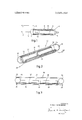
- FIG. I is a longitudinal section of a glow discharge lamp according to the invention.
- FIG. 2 is a perspective view of a second glow discharge lamp according to the invention.
- FIG. 3 is a longitudinal section of the lamp of FIG. 2.
- reference numerals l and 2 denote connection terminals, which are intended to be connected to an alternating voltage supply of 220 v., 50 Hz.
- An electric conductor 4 is connected between terminal I and a glow discharge lamp 3.
- An electric conductor 5 is connected between the terminal 2 and the glow discharge lamp 3.
- the lamp 3 comprises a light transmitting cylindrical part 6, an endpart 7 in the form of a hemispherical bead and an endpart 8 having an arclike profile.
- the glow discharge lamp has a length of approximately 3 cm.
- the cylindrical envelope 6 consists of an external electrically conductive transparent layer 9 which is provided on the outer side of the envelope 6.
- the envelope 6 further includes a layer of a ceramic material 10. This material mainly consists of barium titanate.
- the interior of the envelope 6 includes a second transparent electric layer 11 which likewise consists of tin oxide.
- the layers 9 and 11 are shown too thickly, namely to clearly indicate their location. Actually, their thickness is at the most a few percents of that of the thickness of the ceramic layer 10.
- the glow discharge lamp 3 further includes a penlike electrode 12 which is provided on the longitudinal axis of the lamp.
- the hemispherical head 7 and the arclike endpiece 8 consist of glass, namely a soft glass the coefficient of expansion of which is substantially equal to that of the ceramic material of the layer 10.
- the arclike portion 8 is the remainder of a pinched glass exhaust tube through which this lamp was exhausted and filled with neon gas during manufacture.
- the electric conductor 4 is connected to the electrically conductive layer 9, for example, by means of a soldered joint.
- the electric conductor 5 is connected between terminal 2 through the glass bead 7 to the penlike electrode 12.
- the lamp 3 if filled with neon gas, whose pressure was approximately 30 torr.
- the external diameter of the lamp was approximately 3 mm. and the internal diameter was approximately 2 mm., as already previously stated the length was approximately 3 cm.
- the length of the cylindrical part 6 was approximately 2 5; cm.
- the combination of the conductive layer 9, the ceramic layer 10 and the conductive layer 11 constitutes a series capacitor for the discharge which takes place in the discharge space encompassed by the envelope of the lamp.
- This combination of three layers also constitutes the cylindrical portion of the envelope of the said lamp.
- the electric current flows via the connection terminal I through the electric conductor 4 to the capacitor plate 9.
- the layer 11, which is the other plate of the capacitor, also functions as an electrode of the lamp 3.
- a current flows from this electrode 11 through the discharge space to the electrode 12 and thence through the electric conductor 5 to the connection terminal 2.
- the lamp described is intended to be used in a sealed housing (not shown) of a transparent insulating material.
- the capacitance of the capacitor of FIG. 1 may approximately be determined by way of the formula:
- the relative dielectric constant of the ceramic intermediate material was approximately 4,000.
- Alter substitution ofl 2.5.10 D JD, 1%, the capacitance C of the capacitor is found to be approximately 14,000 pf.
- a comparatively small resistivity is added to this capacitance, which resistivity is formed by the electric resistance of the transparent electrically conductive coatings.
- the lamp current was approximately 1 ma.
- a capacitance of l4,000 pf. is a satisfactory capacitance for the above-mentioned current source to which the lamp is connected.
- the mechanical strength of the cylindrical envelope 6 is substantially determined by the mechanical strength of the ceramic layer 10.
- the reference numeral 30 again denotes a glow discharge lamp.
- This glow discharge lamp has a light transmitting cylindrical portion 31 which is closed on either side with the aid of glass beads 32 and 33, respectively.
- the cylindrical portion 31 consists of a ceramic support 34 (see also FIG. 3) half the circumference of which is provided with two externally located transparent electric conductors (35, 36).
- a semicylindrical transparent electric conductor 37 is provided internally of the ceramic layer 34.
- the conductor 37 faces the conductor 35 (see also FIG. 3).
- a likewise semicylindrical electrically conductive layer 38 is provided, likewise as the layer 37, internally of the ceramic layer 34.
- the layer 38 faces the transparent electrically conductive layer 36.
- the conductor 35 is connected to a connecting terminal 39, the conductor 36 is connected to a connecting terminal 40.
- These connection terminals 39 and 40 are intended to be connected to an alternating voltage mains of 220 v., 50 Hz.
- the layers 35 and 36 of the glow discharge lamp 30 are covered by a transparent lacquer coating 4].
- the lacquer coating may, however, partly consist of a reflective material.
- THe material of the ceramic layer 34 is the same as that of the layer of the lamp of FIG. 1.
- the material of the transparent conductors is the same as that of the layers 9 and 11 of the lamp of FIG. 1.
- FIG. 3 the locations of the different layers such as the ceramic layer 34 and the electrically conductive layers 35 to 38 inclusive are shown in a longitudinal section of the lamp.
- the coating 41 and the layers 35 to 38 inclusive are shown comparatively too thickly in FIGS. 2 and 3. This has been done for the same reason as stated in the description of the layers 9 and 11 of FIG. 1.
- the lamp of FIGS. 2 and 3 also had a length of approximately 3 cm., an external diameter of 3 mm. and an internal diameter of 2 mm.
- the overall length of the semicylindrical conductors 37 and 38 was approximately 2% cm.
- the lamp current was approximately one-eighth ma.
- the stabilization of the discharge current was carried out by two capacitors, to wit the capacitor including the plates 35 and 37 and the capacitor including the plates 38 and 36. In fact, these capacitors are incorporated in the series circuit 39, 35, 37, the discharge path 38. 36, 40.
- the capacitance of these two capacitors combined is approximately one-eighth of that of the lamp of FIG. 1. With the above-mentioned current source and the above-mentioned lamp current intensity of the glow discharge lamp 30 this also gives a satisfactory stabilization of the glow discharge.
- a cylindrical portion of the lamp envelope is not closed with the aid of a glass bead, but by means of a different closure, for example, a flat thin-walled final portion which is transverse to the longitudinal axis of the lamp.
- a discharge lamp comprising an oblong envelope forming a discharge space, end parts for hermetically sealing said envelope, said envelope essentially consisting of a transparent ceramic dielectric material having a coefficient of expansion substantially equal to that of said end parts, an ionizing gas filling said discharge space, electrodes for producing a gaseous discharge within said envelope, electrically conductive transparent layers on opposite sides of said envelope in confronting relationship, the inner conduction layer functioning as one of said electrodes in said discharge space, the inner and outer conducting layers and said dielectric material forming a ballasting capacitor in series with said discharge space for stabilizing said gaseous discharge within said lamp, an electrode functioning as the second of said electrodes in said discharge space, and terminal means for providing current to said lamp.
- a discharge lamp as claimed in claim 1 further comprising a lacquer coating of a transparent insulating material for said electrically conducting material.
- a discharge lamp as claimed in claim 1 wherein said end parts essentially consist of glass, one of said end parts being in the form of a hemispherical bead and the other having an ar clike profile.
- a discharge lamp comprising an oblong envelope forming a discharge space, end parts for hermetically sealing said envelope, said envelope essentially consisting of a transparent ceramic dielectric material having a coefficient of expansion substantially equal to that of said end parts, an ionizing gas filling said discharge space, at least one pair of electrically conductive transparent layers spaced apart on opposite sides of said envelope in confronting relationships, the internal conducting layer functioning as an electrode for producing a gaseous discharge, the inner and outer conducting layers and said dielectric material forming a ballasting capacitor in series with said discharge space to stabilize said gaseous discharge within said lamp, and terminal means connected to said external conducting layers for providing current to said lamp.
Landscapes
- Vessels And Coating Films For Discharge Lamps (AREA)
Abstract
A low-pressure glow discharge lamp having an envelope encompassing the discharge space formed from a ceramic dielectric material which is coated by layers of electrical conducting material to function as a self-ballasting capacitor for stabilizing the electric discharge in the lamp.
Description
United States Patent Willemsen LOW-PRESSURE DISCHARGE LAMP HAVING AN ENVELOPE ENCOMPASSING THE DISCHARGE SPACE AND CONSISTING INTER ALIA OF A SUPPORT Inventor: Petrus Johannes Marie Willemsen, Em-
masingel, Eindhoven, Netherlands Assignee: U.S. Philips Corporation, New York, N.Y.
Filed: Sept. 16, 1969 Appl. No.: 858,289
Foreign Application Priority Data Sept 19, 1968 Germany ..G 67 53 632 US. Cl ..313/221, 313/201, 313/210,
313/217, 313/220 Int. Cl. ..II0lj 17/16 FieldofSearch ..313/201,210,217,220,109,
[ Mar. 14, 1972 Primary Examiner-Raymond F. I-Iossfeld Att0rneyFrank R. Trifari [57] ABSTRACT A low-pressure glow discharge lamp having an envelope encompassing the discharge space formed from a ceramic dielectric material which is coated by layers of electrical conducting material to function as a self-ballasting capacitor for stabilizing the electric discharge in the lamp.
10 Claims, 3 Drawing Figures PATENTEBMAR 14 I972 INVENTOR. PETRUS J.M.WILLEMSEN ACE/VT LOW-PRESSURE DISCHARGE LAMP HAVING AN ENVELOPE ENCOMPASSING THE DISCHARGE SPACE AND CONSISTING INTER ALIA OF A SUPPORT The invention relates to a low-pressure discharge lamp having an envelope encompassing the discharge space and consisting inter alia of a support in which at least a portion of the envelope comprises a layer of transparent ceramic material and a transparent electrically conductive layer, the last-mentioned layer being provided on the side of the ceramic layer remote from the discharge, the transparent electrically conductive layer being a current supply conductor of the lamp.
In a known lamp of the kind described, the transparent electrically conductive layer is formed by a capacitor plate, whose ceramic layer is the dielectric, which capacitor serves to stabilize the discharge in the lamp. An advantage of this known lamp which has been described, for example, in Us. Pat. specification No. 2,654,042 is that a separate series capacitor is not required.
A drawback of this known lamp is that the envelope encompassing the discharge space is provided with a glass support. This glass makes the envelope of the known lamp complicated. In fact, both the transparent electrically conductive layers and the ceramic layer are still present on the internal side of the envelope of the known lamp.
Although it is known from another embodiment of the above-mentioned US. Pat. specification to obtain a simple structure of the envelope by using the glass support as a dielectric of the ballasting capacitor, this solution has the drawback that the required capacitance of the capacitor can sometimes only be obtained when using a very thin glass sup port or when using a high frequency of the electrical supply voltage of the lamp. A thin glass support of course gives rise to a very vulnerable lamp and the use of a high frequency causes a complication in the supply circuit of the lamp.
It is an object of the present invention to provide a discharge lamp which has both a simple but robust structure of the envelope and has a capacitor impedance which is satisfactory for stabilizing when being fed by a normal low-frequency alternating voltage supply.
A low-pressure discharge lamp according to the invention having an envelope encompassing the discharge space and consisting inter alia of a support and in which at least a portion of this envelope comprises a layer of transparent ceramic material and a transparent electrically conductive layer, the last-mentioned layer being provided on the side of the ceramic layer remote from the discharge, and the transparent electrically conductive layer being a current supply conductor of the lamp is characterized in that the lamp is a glow discharge lamp and that in a cross section of the envelope at the area of the ceramic layer the support of the envelope is constituted by said layer.
An advantage of this lamp is that the ceramic layer performs two functionsv The ceramic layer serves as a dielectric for the stabilizing capacitor, but also as a supporting portion of the envelope. The latter means that the mechanical strength of the envelope is mainly determined by the mechanical strength of the ceramic layer. Such a combination of the two functions of the ceramic layer was found to be possible in glow discharge lamps. On the one hand this has to be ascribed to the comparatively small values of the required series capacitances for glow discharge lamps, and on the other hand to the comparatively small dimensions of these lamps, and this because the use of this ceramic material makes it possible to obtain both a sufficiently high ballasting impedance of the capacitor and a still acceptable light transmission due to the small envelope section required on account of mechanical considerations.
In a lamp according to the invention the other electrode of the series capacitor is formed for example, by ionized gas in the discharge space during operation of the lamp.
In a lamp according to the invention the envelope on the side of the ceramic layer facing the discharge is preferably provided with a second transparent electrically conductive layer which is in contact with the discharge space.
An advantage thereof is that the ignition voltage of the lamp may be comparatively small, because the second transparent electrically conducive layer may now function as the lamp electrode which may have a work function which is low for electrons.
In a further advantageous embodiment of a glow discharge lamp according to the invention the lamp is oblong and is provided with a penlike electrode the longitudinal axis of which substantially coincides with the longitudinal axis of the lamp.
An advantage of this embodiment is that the glow discharge lamp in this case may have a light distribution wherein the light intensity in a flat plane at right angles to the longitudinal axis of the lamp is substantially the same in any direction.
In a further embodiment, the lamp is oblong, the envelope near one end of the lamp consisting of glass.
An advantage of this embodiment is that during the manufacturing process the ends of the lamp can easily be sealed in a vacuumtight manner. In fact, this is a simple matter when using glass.
It is feasible that only one end of the lamp is made of glass, for example, an end to which an exhaust tube was secured. It is also feasible that both ends of the lamp are provided with a glass part of the envelope. One of these parts or both parts consist, for example, of glass beads.
In a further preferred embodiment according to the invention the lamp includes an envelope having both a second transparent electrically conductive layer and a third transparent electrically conductive layer, the two coatings being in contact with the discharge space, and the electric resistance of the envelop between the third and the second transparent electrically conductive layer being highly resistive, the discharge current of the lamp flowing through the third electrically conductive layer. A highly resistive electric resistance is understood to mean a resistance in the order of that of an isolator.
An advantage of this lamp is that the light radiation in this case is substantially not influenced by the lamp electrodes.
The third electrically conductive layer may be connected, for example, to a connection wire which protrudes through the envelope of the discharge space.
A lamp according to the invention preferably has not only the said first, second and third transparent electrically conductive layers, but also a fourth transparent electrically conductive layer, which fourth layer is provided on the side of the ceramic layer remote from the discharge, all this in such a manner that the electric resistance of the envelope between the fourth electrically conductive layer and the first electrically conductive layer is highly resistive, the fourth electrically conductive layer being a current supply conductor of the lamp, the second conductive layer facing the first conductive layer and the third conducive layer facing the fourth conductive layer.
In this case connection wires through the envelope of the discharge space are superfluous. In fact, the lamp is now fed through the first and the fourth transparent electric conductor. Going from the first transparent conductor the current passes successively a first series capacitor, the discharge path and a second series capacitor. Then the current has reached the fourth transparent electric conductor.
In certain cases, for example, when the lamp is incorporated in a permanently closed housing of, for example, synthetic plastic material, a transparent electric conductor may form the exterior of the lamp.
The exterior of the envelope preferably consists of a coating of a transparent insulation material, particularly a transparent lacquer coating.
An advantage of the last-mentioned embodiment is that the lamp can safely be touched by hand.
In order that the invention may be readily carried into effect, a few embodiments thereof will now be described in detail by way of example, with reference to the accompanying diagrammatic drawing in which:
FIG. I is a longitudinal section of a glow discharge lamp according to the invention;
FIG. 2 is a perspective view of a second glow discharge lamp according to the invention;
FIG. 3 is a longitudinal section of the lamp of FIG. 2.
In FIG. 1, reference numerals l and 2 denote connection terminals, which are intended to be connected to an alternating voltage supply of 220 v., 50 Hz. An electric conductor 4 is connected between terminal I and a glow discharge lamp 3. An electric conductor 5 is connected between the terminal 2 and the glow discharge lamp 3. The lamp 3 comprises a light transmitting cylindrical part 6, an endpart 7 in the form of a hemispherical bead and an endpart 8 having an arclike profile. The glow discharge lamp has a length of approximately 3 cm. The cylindrical envelope 6 consists of an external electrically conductive transparent layer 9 which is provided on the outer side of the envelope 6. In this case this layer consists of tin oxide, but it is feasible that a different material, for example, indium oxide is used for this purpose. The envelope 6 further includes a layer of a ceramic material 10. This material mainly consists of barium titanate. The interior of the envelope 6 includes a second transparent electric layer 11 which likewise consists of tin oxide. In FIG. I the layers 9 and 11 are shown too thickly, namely to clearly indicate their location. Actually, their thickness is at the most a few percents of that of the thickness of the ceramic layer 10. The glow discharge lamp 3 further includes a penlike electrode 12 which is provided on the longitudinal axis of the lamp. The hemispherical head 7 and the arclike endpiece 8 consist of glass, namely a soft glass the coefficient of expansion of which is substantially equal to that of the ceramic material of the layer 10. The arclike portion 8 is the remainder of a pinched glass exhaust tube through which this lamp was exhausted and filled with neon gas during manufacture. The electric conductor 4 is connected to the electrically conductive layer 9, for example, by means of a soldered joint. The electric conductor 5 is connected between terminal 2 through the glass bead 7 to the penlike electrode 12. The lamp 3 if filled with neon gas, whose pressure was approximately 30 torr. The external diameter of the lamp was approximately 3 mm. and the internal diameter was approximately 2 mm., as already previously stated the length was approximately 3 cm. The length of the cylindrical part 6 was approximately 2 5; cm.
In the lamp described the combination of the conductive layer 9, the ceramic layer 10 and the conductive layer 11 constitutes a series capacitor for the discharge which takes place in the discharge space encompassed by the envelope of the lamp. This combination of three layers also constitutes the cylindrical portion of the envelope of the said lamp. The electric current flows via the connection terminal I through the electric conductor 4 to the capacitor plate 9. The layer 11, which is the other plate of the capacitor, also functions as an electrode of the lamp 3. A current flows from this electrode 11 through the discharge space to the electrode 12 and thence through the electric conductor 5 to the connection terminal 2. The lamp described is intended to be used in a sealed housing (not shown) of a transparent insulating material.
The capacitance of the capacitor of FIG. 1 may approximately be determined by way of the formula:
C the capacitance in F arad; E, the relative dielectric constant of the intermediate layer 10;
l= the length of the cylinder 6 in meter; and
D D, the ratio between the external diameter of the lamp and the internal diameter of the lamp.
In the relevant case the relative dielectric constant of the ceramic intermediate material was approximately 4,000. Alter substitution ofl= 2.5.10 D JD, 1%, the capacitance C of the capacitor is found to be approximately 14,000 pf. A comparatively small resistivity is added to this capacitance, which resistivity is formed by the electric resistance of the transparent electrically conductive coatings.
C E of a cylindrical capacitor; wherein:
In the case of the glow discharge lamp described the lamp current was approximately 1 ma. A capacitance of l4,000 pf. is a satisfactory capacitance for the above-mentioned current source to which the lamp is connected.
The mechanical strength of the cylindrical envelope 6 is substantially determined by the mechanical strength of the ceramic layer 10.
In FIG. 2 the reference numeral 30 again denotes a glow discharge lamp. This glow discharge lamp has a light transmitting cylindrical portion 31 which is closed on either side with the aid of glass beads 32 and 33, respectively. The cylindrical portion 31 consists of a ceramic support 34 (see also FIG. 3) half the circumference of which is provided with two externally located transparent electric conductors (35, 36). A semicylindrical transparent electric conductor 37 is provided internally of the ceramic layer 34. The conductor 37 faces the conductor 35 (see also FIG. 3). A likewise semicylindrical electrically conductive layer 38 is provided, likewise as the layer 37, internally of the ceramic layer 34. The layer 38 faces the transparent electrically conductive layer 36. The conductor 35 is connected to a connecting terminal 39, the conductor 36 is connected to a connecting terminal 40. These connection terminals 39 and 40 are intended to be connected to an alternating voltage mains of 220 v., 50 Hz. The layers 35 and 36 of the glow discharge lamp 30 are covered by a transparent lacquer coating 4].
If desired, the lacquer coating may, however, partly consist of a reflective material. THe material of the ceramic layer 34 is the same as that of the layer of the lamp of FIG. 1. The material of the transparent conductors is the same as that of the layers 9 and 11 of the lamp of FIG. 1.
In FIG. 3 the locations of the different layers such as the ceramic layer 34 and the electrically conductive layers 35 to 38 inclusive are shown in a longitudinal section of the lamp. The coating 41 and the layers 35 to 38 inclusive are shown comparatively too thickly in FIGS. 2 and 3. This has been done for the same reason as stated in the description of the layers 9 and 11 of FIG. 1.
The lamp of FIGS. 2 and 3 also had a length of approximately 3 cm., an external diameter of 3 mm. and an internal diameter of 2 mm. The overall length of the semicylindrical conductors 37 and 38 was approximately 2% cm. In the relevant case the lamp current was approximately one-eighth ma. In this case the stabilization of the discharge current was carried out by two capacitors, to wit the capacitor including the plates 35 and 37 and the capacitor including the plates 38 and 36. In fact, these capacitors are incorporated in the series circuit 39, 35, 37, the discharge path 38. 36, 40. The capacitance of these two capacitors combined is approximately one-eighth of that of the lamp of FIG. 1. With the above-mentioned current source and the above-mentioned lamp current intensity of the glow discharge lamp 30 this also gives a satisfactory stabilization of the glow discharge.
It is feasible that a cylindrical portion of the lamp envelope is not closed with the aid of a glass bead, but by means ofa different closure, for example, a flat thin-walled final portion which is transverse to the longitudinal axis of the lamp.
What is claimed is:
I. A discharge lamp comprising an oblong envelope forming a discharge space, end parts for hermetically sealing said envelope, said envelope essentially consisting of a transparent ceramic dielectric material having a coefficient of expansion substantially equal to that of said end parts, an ionizing gas filling said discharge space, electrodes for producing a gaseous discharge within said envelope, electrically conductive transparent layers on opposite sides of said envelope in confronting relationship, the inner conduction layer functioning as one of said electrodes in said discharge space, the inner and outer conducting layers and said dielectric material forming a ballasting capacitor in series with said discharge space for stabilizing said gaseous discharge within said lamp, an electrode functioning as the second of said electrodes in said discharge space, and terminal means for providing current to said lamp.
2. A discharge lamp as claimed in claim 1 wherein said second electrode is positioned along the longitudinal axis of said lamp.
3. A discharge lamp as claimed in claim 1 wherein said transparent ceramic dielectric material essentially consists of barium titanate and said electrically conducting material essentially consists of tin oxide.
4. A discharge lamp as claimed in claim 1 further comprising a lacquer coating of a transparent insulating material for said electrically conducting material.
5. A discharge lamp as claimed in claim 4 wherein said lacquer coating partly consists of a reflective material.
6. A discharge lamp as claimed in claim 1 wherein said end parts essentially consist of glass, one of said end parts being in the form of a hemispherical bead and the other having an ar clike profile.
7. A discharge lamp as claimed in claim 1 wherein said end parts are flat thin walled portions positioned transverse to the longitudinal axis of said lamp.
8. A discharge lamp as claimed in claim 1 wherein said internal electrically conductive, transparent layer has a low work function.
9. A discharge lamp comprising an oblong envelope forming a discharge space, end parts for hermetically sealing said envelope, said envelope essentially consisting of a transparent ceramic dielectric material having a coefficient of expansion substantially equal to that of said end parts, an ionizing gas filling said discharge space, at least one pair of electrically conductive transparent layers spaced apart on opposite sides of said envelope in confronting relationships, the internal conducting layer functioning as an electrode for producing a gaseous discharge, the inner and outer conducting layers and said dielectric material forming a ballasting capacitor in series with said discharge space to stabilize said gaseous discharge within said lamp, and terminal means connected to said external conducting layers for providing current to said lamp.
10. A discharge lamp as claimed in claim 9 wherein said electrically conductive transparent layers have a semicylindrical shape.
mg mm'mn STATES PATIENT owner:
CERTHEFMATE @F QQRREQTWN Patent No. 3649864 Dated May 4, 1972 Inventor) PETRUS JOHANNES MARIE WILLEMSEN It is certified that error appears in the above-identified patent and that said Letters Patent are hereby corrected as shown below:
(SEAL) Attest:
EDWARD MQFLE'ZGIER JRO ROBERT GOTTSCHALK Attesting Officer Commissioner of Patents
Claims (10)
1. A discharge lamp comprising an oblong envelope forming a discharge space, end parts for hermetically sealing said envelope, said envelope essentially consisting of a transparent ceramic dielectric material having a coefficient of expansion substantially equal to that of said end parts, an ionizing gas filling said discharge space, electrodes for producing a gaseous discharge within said envelope, electrically conductive transparent layers on opposite sides of said envelope in confronting relationship, the inner conduction layer functioning as one of said electrodes in said discharge space, the inner and outer conducting layers and said dielectric material forming a ballasting capacitor in series with said discharge space for stabilizing said gaseous discharge within said lamp, an electrode functioning as the second of said electrodes in said discharge space, and terminal means for providing current to said lamp.
2. A discharge lamp as claimed in claim 1 wherein said second electrode is positioned along the longitudinal axis of said lamp.
3. A discharge lamp as claimed in claim 1 wherein said transparent ceramic dielectric material essentially consists of barium titanate and said electrically conducting material essentially consists of tin oxide.
4. A discharge lamp as claimed in claim 1 further comprising a lacquer coating of a transparent insulating material for said electrically conducting material.
5. A discharge lamp as claimed in claim 4 wherein said lacquer coating partly consists of a reflective material.
6. A discharge lamp as claimed in claim 1 wherein said end parts essentially consist of glass, one of said end parts being in the form of a hemispherical bead and the other having an arclike profile.
7. A discharge lamp as claimed in claim 1 wherein said end parts are flat thin walled portions positioned transverse to the longitudinal axis of said lamp.
8. A discharge lamp as claimed in claim 1 wherein said internal electrically conductive, transparent layer has a low work function.
9. A discharge lamp comprising an oblong envelope forming a discharge space, end parts for hermetically sealing said envelope, said envelope essentially consisting of a transparent ceramic dielectric material having a coefficient of expansion substantially equal to that of said end parts, an ionizing gas filling said discharge space, at least one pair of electrically conductive transparent layers spaced apart on opposite sides of said envelope in confronting relationships, the internal conducting layer functioning as an electrode for producing a gaseous discharge, the inner and outer conducting layers and said dielectric material forming a ballasting capacitor in series with said discharge space to stabilize said gaseous discharge within said lamp, and terminal means connected to said external conducting layers for providing current to said lamp.
10. A discharge lamp as claimed in claim 9 wherein said electrically conductive transparent layErs have a semicylindrical shape.
Applications Claiming Priority (1)
| Application Number | Priority Date | Filing Date | Title |
|---|---|---|---|
| DE6753632U DE6753632U (en) | 1968-09-19 | 1968-09-19 | LOW PRESSURE DISCHARGE LAMP WITH A WALL NOT CLOSING THE DISCHARGE SPACE, THAT U.A. CONSISTS OF A BEAM. |
Publications (1)
| Publication Number | Publication Date |
|---|---|
| US3649864A true US3649864A (en) | 1972-03-14 |
Family
ID=6593563
Family Applications (1)
| Application Number | Title | Priority Date | Filing Date |
|---|---|---|---|
| US858289A Expired - Lifetime US3649864A (en) | 1968-09-19 | 1969-09-16 | Low-pressure discharge lamp having an envelope encompassing the discharge space and consisting inter alia of a support |
Country Status (4)
| Country | Link |
|---|---|
| US (1) | US3649864A (en) |
| DE (1) | DE6753632U (en) |
| FR (1) | FR2018417A1 (en) |
| GB (1) | GB1282513A (en) |
Cited By (15)
| Publication number | Priority date | Publication date | Assignee | Title |
|---|---|---|---|---|
| US4174944A (en) * | 1978-01-30 | 1979-11-20 | Gte Sylvania Incorporated | Single lead electrically-activated flashlamp |
| US4370597A (en) * | 1981-01-12 | 1983-01-25 | The United States Of America As Represented By The Secretary Of The Army | Thyratron switch for narrow pulses |
| US4837484A (en) * | 1986-07-22 | 1989-06-06 | Bbc Brown, Boveri Ag | High-power radiator |
| US5311097A (en) * | 1992-03-04 | 1994-05-10 | Rockwell International Corporation | Fluorescent lamp apparatus for avionics liquid crystal displays |
| US5519285A (en) * | 1992-12-15 | 1996-05-21 | Matsushita Electric Works, Ltd. | Electrodeless discharge lamp |
| US5994849A (en) * | 1995-07-18 | 1999-11-30 | Patent-Treuhand-Gesellschaft Fuer Electrische Gluehlampen Mbh | Method for operating a lighting system and suitable lighting system therefor |
| US6614185B1 (en) * | 1999-06-07 | 2003-09-02 | Toshiba Lighting & Technology Corporation | Discharge tube with interior and exterior electrodes |
| US6713946B2 (en) * | 2001-06-01 | 2004-03-30 | Koninklijke Philips Electronics N.V. | Liquid crystal picture screen with improved backlighting |
| US6744204B2 (en) * | 2001-05-09 | 2004-06-01 | Koninklijke Philips Electronics N.V. | Gas discharge lamp |
| US6762556B2 (en) | 2001-02-27 | 2004-07-13 | Winsor Corporation | Open chamber photoluminescent lamp |
| US20050127839A1 (en) * | 2003-12-12 | 2005-06-16 | Lg Philips Lcd Co., Ltd. | Fluorescent lamp and backlight |
| US6916559B2 (en) * | 1997-02-26 | 2005-07-12 | Kyocera Corporation | Ceramic material resistant to halogen plasma and member utilizing the same |
| US20060170360A1 (en) * | 2003-03-18 | 2006-08-03 | Koninklijke Philips Electronics N. V. | Gas discharge lamp |
| US20060186815A1 (en) * | 2003-03-18 | 2006-08-24 | Norbert Lesch | Gas discharge lamp |
| JP2016062678A (en) * | 2014-09-16 | 2016-04-25 | ウシオ電機株式会社 | Rare gas fluorescent lamp |
Families Citing this family (3)
| Publication number | Priority date | Publication date | Assignee | Title |
|---|---|---|---|---|
| NL8500736A (en) * | 1985-03-14 | 1986-10-01 | Philips Nv | ELECTRESSLESS LOW PRESSURE DISCHARGE LAMP. |
| JPS62252061A (en) * | 1986-04-22 | 1987-11-02 | 周 成祥 | Composite color light emitting discharge lamp |
| JPS63146343A (en) * | 1986-07-15 | 1988-06-18 | Toshiba Corp | discharge lamp |
Citations (6)
| Publication number | Priority date | Publication date | Assignee | Title |
|---|---|---|---|---|
| US2004577A (en) * | 1931-10-15 | 1935-06-11 | Iris Licht G M B H | Process and apparatus for the production of luminous signs in electric gas dischargetubes |
| GB456184A (en) * | 1935-08-09 | 1936-11-04 | Patent Treuhand Ges Fuer Elektrische Gluehlampen Mbh | Improvements in luminous electric discharge lamps |
| US2654042A (en) * | 1949-07-29 | 1953-09-29 | Gen Electric | Integrally capacitively ballasted discharge lamp |
| US2822496A (en) * | 1956-12-05 | 1958-02-04 | Maurer Georg | Low-voltage gas discharge illumination device |
| US2925511A (en) * | 1958-07-15 | 1960-02-16 | Tung Sol Electric Inc | Cold cathode vacuum lamp |
| US3363134A (en) * | 1965-12-08 | 1968-01-09 | Gen Electric | Arc discharge lamp having polycrystalline ceramic arc tube |
-
1968
- 1968-09-19 DE DE6753632U patent/DE6753632U/en not_active Expired
-
1969
- 1969-09-16 US US858289A patent/US3649864A/en not_active Expired - Lifetime
- 1969-09-16 GB GB45548/69A patent/GB1282513A/en not_active Expired
- 1969-09-18 FR FR6931745A patent/FR2018417A1/fr not_active Withdrawn
Patent Citations (6)
| Publication number | Priority date | Publication date | Assignee | Title |
|---|---|---|---|---|
| US2004577A (en) * | 1931-10-15 | 1935-06-11 | Iris Licht G M B H | Process and apparatus for the production of luminous signs in electric gas dischargetubes |
| GB456184A (en) * | 1935-08-09 | 1936-11-04 | Patent Treuhand Ges Fuer Elektrische Gluehlampen Mbh | Improvements in luminous electric discharge lamps |
| US2654042A (en) * | 1949-07-29 | 1953-09-29 | Gen Electric | Integrally capacitively ballasted discharge lamp |
| US2822496A (en) * | 1956-12-05 | 1958-02-04 | Maurer Georg | Low-voltage gas discharge illumination device |
| US2925511A (en) * | 1958-07-15 | 1960-02-16 | Tung Sol Electric Inc | Cold cathode vacuum lamp |
| US3363134A (en) * | 1965-12-08 | 1968-01-09 | Gen Electric | Arc discharge lamp having polycrystalline ceramic arc tube |
Cited By (18)
| Publication number | Priority date | Publication date | Assignee | Title |
|---|---|---|---|---|
| US4174944A (en) * | 1978-01-30 | 1979-11-20 | Gte Sylvania Incorporated | Single lead electrically-activated flashlamp |
| US4370597A (en) * | 1981-01-12 | 1983-01-25 | The United States Of America As Represented By The Secretary Of The Army | Thyratron switch for narrow pulses |
| US4837484A (en) * | 1986-07-22 | 1989-06-06 | Bbc Brown, Boveri Ag | High-power radiator |
| US5311097A (en) * | 1992-03-04 | 1994-05-10 | Rockwell International Corporation | Fluorescent lamp apparatus for avionics liquid crystal displays |
| US5519285A (en) * | 1992-12-15 | 1996-05-21 | Matsushita Electric Works, Ltd. | Electrodeless discharge lamp |
| US5994849A (en) * | 1995-07-18 | 1999-11-30 | Patent-Treuhand-Gesellschaft Fuer Electrische Gluehlampen Mbh | Method for operating a lighting system and suitable lighting system therefor |
| US6916559B2 (en) * | 1997-02-26 | 2005-07-12 | Kyocera Corporation | Ceramic material resistant to halogen plasma and member utilizing the same |
| US6614185B1 (en) * | 1999-06-07 | 2003-09-02 | Toshiba Lighting & Technology Corporation | Discharge tube with interior and exterior electrodes |
| US6762556B2 (en) | 2001-02-27 | 2004-07-13 | Winsor Corporation | Open chamber photoluminescent lamp |
| US6744204B2 (en) * | 2001-05-09 | 2004-06-01 | Koninklijke Philips Electronics N.V. | Gas discharge lamp |
| US6713946B2 (en) * | 2001-06-01 | 2004-03-30 | Koninklijke Philips Electronics N.V. | Liquid crystal picture screen with improved backlighting |
| US20060170360A1 (en) * | 2003-03-18 | 2006-08-03 | Koninklijke Philips Electronics N. V. | Gas discharge lamp |
| US20060186815A1 (en) * | 2003-03-18 | 2006-08-24 | Norbert Lesch | Gas discharge lamp |
| US7511431B2 (en) * | 2003-03-18 | 2009-03-31 | Koninklijke Philips Electronics N.V. | Gas discharge lamp |
| US7550925B2 (en) * | 2003-03-18 | 2009-06-23 | Koninklijke Philips Electronics N.V. | Gas discharge lamp with reduced electromagnetic interference radiation |
| US20050127839A1 (en) * | 2003-12-12 | 2005-06-16 | Lg Philips Lcd Co., Ltd. | Fluorescent lamp and backlight |
| US7768186B2 (en) * | 2003-12-12 | 2010-08-03 | Lg. Display Co., Ltd. | Fluorescent lamp and backlight unit using the same, and method of driving the backlight unit |
| JP2016062678A (en) * | 2014-09-16 | 2016-04-25 | ウシオ電機株式会社 | Rare gas fluorescent lamp |
Also Published As
| Publication number | Publication date |
|---|---|
| DE6753632U (en) | 1969-05-29 |
| FR2018417A1 (en) | 1970-05-29 |
| GB1282513A (en) | 1972-07-19 |
Similar Documents
| Publication | Publication Date | Title |
|---|---|---|
| US3649864A (en) | Low-pressure discharge lamp having an envelope encompassing the discharge space and consisting inter alia of a support | |
| US5990599A (en) | High-pressure discharge lamp having UV radiation source for enhancing ignition | |
| US4260929A (en) | High-pressure sodium vapor discharge lamp | |
| JPS6074260A (en) | General incandescent lamp | |
| JPH01134848A (en) | Arc discharge lamp with ultraviolet starter | |
| CA1302476C (en) | Arc discharge lamp with electrodeless ultraviolet radiation starting source | |
| GB2174238A (en) | Electrodeless low-pressure discharge lamp | |
| US4987344A (en) | Arc discharge lamp with internal starter | |
| US3753036A (en) | Integrated fluorescent lamp unit | |
| US2654042A (en) | Integrally capacitively ballasted discharge lamp | |
| US2346522A (en) | Fluorescent lamp | |
| JPS61190850A (en) | Dual cathode dual beam mode fluorescent lamp with capacitivestabilizer | |
| US4004189A (en) | Three-electrode short duration flash tube | |
| US5838104A (en) | Shield for high pressure discharge lamps | |
| US3982154A (en) | Arc discharge lamp construction for starter electrode voltage doubling | |
| WO1999049493A1 (en) | External electrode driven discharge lamp | |
| JPS63146343A (en) | discharge lamp | |
| US3895248A (en) | Gas discharge device with glow discharge igniting structure | |
| US6507151B1 (en) | Gas discharge lamp with a capactive excitation structure | |
| US2739261A (en) | Tubular gas discharge lamp | |
| KR20140048194A (en) | High intensity discharge lamp with ignition aid | |
| US5334906A (en) | Metal halide arc discharge lamp having short arc length | |
| US4032814A (en) | Fluorescent lamp with reduced wattage consumption | |
| US2004564A (en) | Gaseous electric discharge lamp device | |
| US3706898A (en) | High pressure electric discharge lamp |