US3649816A - Control system for hydraulic extrusion press - Google Patents
Control system for hydraulic extrusion press Download PDFInfo
- Publication number
- US3649816A US3649816A US87903A US3649816DA US3649816A US 3649816 A US3649816 A US 3649816A US 87903 A US87903 A US 87903A US 3649816D A US3649816D A US 3649816DA US 3649816 A US3649816 A US 3649816A
- Authority
- US
- United States
- Prior art keywords
- billet
- stem
- length
- control system
- die
- Prior art date
- Legal status (The legal status is an assumption and is not a legal conclusion. Google has not performed a legal analysis and makes no representation as to the accuracy of the status listed.)
- Expired - Lifetime
Links
Images
Classifications
-
- B—PERFORMING OPERATIONS; TRANSPORTING
- B21—MECHANICAL METAL-WORKING WITHOUT ESSENTIALLY REMOVING MATERIAL; PUNCHING METAL
- B21C—MANUFACTURE OF METAL SHEETS, WIRE, RODS, TUBES, PROFILES OR LIKE SEMI-MANUFACTURED PRODUCTS OTHERWISE THAN BY ROLLING; AUXILIARY OPERATIONS USED IN CONNECTION WITH METAL-WORKING WITHOUT ESSENTIALLY REMOVING MATERIAL
- B21C31/00—Control devices for metal extruding, e.g. for regulating the pressing speed or temperature of metal; Measuring devices, e.g. for temperature of metal, combined with or specially adapted for use in connection with extrusion presses
Definitions
- ABSTRACT A computer control system for hydraulic extrusion presses and the like characterized in that the operator need only preset at a control console certain lengths and distances dictated by the characteristics of the billet to be extruded, without the necessity for setting limit switches on the press itself. Aside from this, the operation of the press is automatic during an extrusion cycle, resulting in smoother operation of the press, improvements in yield and greater uniformity of product. In addition, the control system incorporates an automatic slowdown of the stem before it contacts a dummy block and billet, thereby reducing damage to dies.
- press control systems of the type described above are generally satisfactory for slow speed presses, they have certain deficiencies at high speeds.
- the press is rough and noisy in its operation.
- the stem contacts the billet at rapid advance speed, causing the billet to strike the die or die holder at this rapid speed which may injure the die or the ceramic coating of the die in the case of a Sejoumet-type extrusion press.
- the stem speed may, and usually does, vary widely not only during any single extrusion stroke but also from cycle to cycle, thus affecting the uniformity of the product.
- limit switches since the system uses limit switches these must be relocated at times, an operation which requires skill and precision and which is time consuming.
- the use of a limit switch to stop the stem at the end of its stroke does not facilitate easy adjustment of the discard length of the billet remaining in the billet holder, a factor which tends to reduce yield.
- a control system for an extrusion press in which the position of the stem with respect to an extrusion die is monitored by means of a pulse generator which generates a number of pulses proportional to the travel of the stem from its stationary, fully retracted position.
- the operator initially enters into the control system by thumbwheel switches or the like the length of the press tool stack, the length of the stem and the dummy block length. In many cases, these will remain constant from billet to billet but may vary for each billet as in the case where special metals, such as titanium,.are being extruded on ajobshop basis.
- the operator enters the length of the billet being extruded, the desired discard length, the desired slowdown distance of the stem from fast advance and the desired slowdown distance of the stem from extrusion speed. From these quantities, and taking into account the total distance between the stem in its fully retracted position and the end of the tool stack, the position of the stem for slowdown from fast advance, for slowdown from extrude speed,
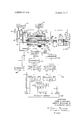
- one type of extrusion press installation includes a main, stationary crosshead 10 which carries a main power cylinder 12 and two rapid advance and pullback cylinders 14 and 16.
- Reciprocable within the main power cylinder 12 is a ram-type piston 18 connected at its forward end to a reciprocable main crosshead 20 which can travel back and forth on guideways, not shown.
- the cylinders 14 and 16 have pistons 21 therein which are connected through piston rods 22 to the main crosshead 20 on either side of the ram-type piston 18.
- the main crosshead 20, in turn, carries a stem 24 on its forward face.
- the stem is hollow and receives a piercer ram 26.
- the ram 26 is utilized in the case of hollow extrusions and extends through a bore in a billet.
- Separate hydraulic cylinders, not shown, are provided for causing the piercer ram 26 to extend out beyond the end of the stem 24.
- a billet container 28 provided with an internal bore 30 having at its one end a die 32 which is backed up by a tool stack or tool block 34 which, in turn, engages a tail block 36 secured to the press foundation.
- Hydraulic fluid for actuating the cylinders 12, 14 and 16 is supplied from a reservoir 42.
- the fluid from the reservoir 42 is pumped by means of a pump 44, driven by motor 45, to one of two hydraulic conduits 46 or 48.
- the motor 45 continually rotates in one direction; while the pump 44 is preferably of the reversible, variable volume type controlled mechanically by a pump control unit 64 to cause fluid under variable pressure to flow from either one of the two pump output ports.
- the condition of the pump 44 is such as to pressurize conduit 46, the pistons 21 within cylinders 14 and 16 are caused to move to the right as viewed in the drawing. This causes the main crosshead 20 to move to the right also, thereby pulling the ram-type piston 18 to the right.
- a dumping valve 50 permits liquid from the reservoir 42, which is usually located above the cylinder 12, to flow by gravity into the left end of the cylinder 12 vacated by the advancing piston 18 which is moving to the right.
- the crosshead 20 and ram-type piston 18 move to the right, the space behind the piston 18 is filled with liquid.
- the billet 38 is initially inserted into the bore 30 in billet holder 28 along with the dummy block 40. This is accomplished by a billet loader, part of any extrusion press, not shown herein. Thereafter, the pump 44 is activated to pressurize conduit 46, thereby forcing pistons 21 in cylinders 14 to the right, causing the crosshead 20, the stem 24 and the ram-type piston 18 to move to the right. During this time, the space within the cylinder 12 being vacated by the piston 18 is constantly being filled with liquid from reservoir 42 as explained above.
- the forward movement of the stem 24 continues until the billet is almost completely extruded; however a certain discard length, identified by the letter D in the drawing, is not extruded to avoid the possibility of jamming the dummy block 40 against the die 32 and damaging the same.
- the cross-sectional area of piston 18 is much greater than the combined areas of pistons 21 such that when the system switches from rapid advance to extrude, the stem slows down, but the pressure it exerts is much greater.
- the billet container 28 is moved away from the die 32 by means, not shown; whereupon the extrusion is severed and the remaining length of the billet (i.e., the discard length) and the dummy block 40 are pushed out of the right end of the bore 30.
- fluid flow through the pump 44 is reversed; conduit 48 is pressurized, and the cylinders l4 and 16 caused to return the crosshead 20, the piston 18 and the stem 24 to the left back into their fully retracted positions shown in the drawing.
- the dumping valve 50 permits fluid from the left end of cylinder 12 to be returned back to the reservoir 42.
- the billet contacts the die with the stem 24 traveling at relatively high speed which sometimes results in damage to the die.
- the system requires the use of a limit switch to stop the movement of the stem 24 at its extreme limit of travel.
- This limit switch is engaged by the crosshead 20 or by an element connected thereto and movable therewith. Positioning the limit switch, in turn, is time consuming and requires a certain amount of skill.
- the quality e.g., density
- a computer control system wherein the position of the stem 24 with respect to the die 32 is constantly monitored by means of a pulse generator 51 connected to a gear 52 which engages a rack 54 carried on the main crosshead 20. It will be appreciated, however, that other and different systems can be utilized to generate a number of pulses indicative of the travel of the stem 24 from its completely retracted position.
- the control system for the extrusion press includes an operators console 55 which, among other things, includes a plurality of thumbwheel switches which feed digital signals into a computer, generally indicated by the reference numeral 56, proportional to certain predetermined lengths.
- the operator inputs include the length of tool stack 34 (TS), the length of billet 38 (B) and the length of stem 24 (S). Each of these is entered on a four-decade thumbwheel switch, not shown, which stops at 39.99 inches maximum.
- the opera tor enters the length of the dummy block 40 (DB), the discard length (D), the slowdown distance from fast advance (SDFA) and the slowdown distance from extrude speed (SDES).
- the slowdown distance from fast advance is that distance which the stem 24 travels at reduced speed with cylinders 14 and 16 being pressurized until the stem forces the billet 38 into engagement with the die 32. This slowdown, as explained above, is for the purpose of preventing damage to the die.
- the slowdown distance from extrude speed is that distance which the stem should travel at the end of an extrusion step at reduced speed.
- the computer 56 utilizes the information entered by the operator to find the distances from the zero reference (i.e., the fully retracted position of stem 24) to the following points on the press:
- the computer 56 is preferably a general purpose computer which may be programmed in accordance with techniques well known to those skilled in the art; however it will be described herein as if it constituted hardward logic.
- the first step in the process which may be performed in a digital subtracter 58, is to determine the quantity AL which is an intermediate quantity used to simplify the computer computation.
- AL is computed from:
- l AL L-TS-S-DB
- the quantity AL in effect, is the total length between the forward edge of the main crosshead 20 and the end of the tool stack 34 minus the length of the tool stack, the length of stem 24, and the dummy block length DB.
- the length of the tool stack must be taken into account since it may vary, depending upon the die used. This, in effect, constitutes the total travel of the stem 24 during a complete extrusion cycle, disregarding the discard length D.
- the quantity D constituting the discard length, must be subtracted from the quantity AL in digital subtracter 60 to determine the quantity LS7, which is the total length of travel of stem 24 during a complete extrusion cycle.
- the digital signal proportional to LS7 is then compared in comparator 62 with the output of an up-down counter 63 connected to pulse generator 51; and when the two are the same, comparator 62 actuates a pump control unit 64 to reduce the output of pump 44 to zero, whereupon the advance of the crosshead 20 and stem 24 will also stop.
- the quantity LS7 is also used in digital subtracter 68 to cal culate the quantity LS7A, the slowdown distance from extrude speed in accordance with the equation:
- the quantity AL is further used in subtracter 72 to determine the quantity CP which is the point of contact between the stem 24 and the dummy block 40 during an extrusion cycle. This is calculated in accordance with the equation:
- CP AL-B where B is the length of billet 38.
- the quantity CP is utilized in subtracter 74 to calculate the quantity L812, the slowdown from fast advance, in accordance with the equation: (4)
- LSl2 CP-SDFA where SDFA is the slowdown distance from fast advance as entered by the operator.
- the quantity L812 is then compared in comparator 76 with the output of up-down counter 63; and when the two are the same, the pump control unit 64 is actu ated to reduce the volumetric output of pump 44 and slow down the stem 24 during the rapid advance cycle.
- the operator will enter the quantities L, TS, S, DB, B, D, SDFA and SDES.
- the quantities TS, S, DB, SDFA and SDES will remain con stant from billet to billet. The operator, therefore, need only be concerned with the billet length B and the discard length D.
- the quantities LS7, LS7A and L812 are computed by computer 56; and the operator initiates the extrusion cycle by control apparatus, not shown.
- the pump control unit 64 causes the pump 44 to pressurize conduit 46 to open valve 50 and permit fluid from reservoir 42 to flow into the left end of cylinder 12 as the rapid advance cylinders 14 and 16 advance the crosshead 20 and the stem 24 to the right. This process will continue until the count of counter 63 matches the output of subtracter 68, meaning that the stem 24 should slow down from fast advance. Consequently, the pump control unit 64 now reduces the volumetric output of pump 44 such that the crosshead 20 and stem 24 slow down just before the stem en gages the dummy block and forces the billet against the die 32.
- the stem 24 will now advance at a reduced speed against the dummy block 40; and when the dummy block is engaged, the pressure in conduit 46 will rise, thereby causing the dumping valve 50 to disconnect the right end of cylinder 12 from reservoir 42 and connect it to the output of pump 44.
- the dumping valve 50 may be of the type shown in Lombard US Pat. No. 2,751,076, issued June 19, 1956.
- the stem will now move to the right under extrusion pressure until the output of subtracter 68 matches the pulses counted by counter 63, whereupon comparator will cause the pump control unit 64 to reduce the output pressure of pump 44 and slow down the advance of stem 24.
- comparator 62 actuates the pump control unit 64 to stop the pump 44, whereupon the extrusion process is completed. Thereafter, the discard length and dummy block are extracted from bore 30 as explained above; and the operator reverses the flow of fluid through pump 44 via unit 64; whereupon the cylinder 12 is connected back to the reservoir 42 while fluid in conduit 48, which is now pressurized, causes the pistons 21 in cylinders 14 and 16 to withdraw the crosshead 20 and stem 24 back to their original starting positions. When the stem is fully retracted, limit switch LS is tripped to reset counter 63 to zero in the event that it has not counted down to zero during the reverse stroke.
- control action of the invention prevents damage to extrusion dies and at the same time insures that the quality of resulting extrusions will be constant. At the same time, the yield is materially increased since the operator can determine with a higher degree of precision the minimum possible discard length
- control system of claim 1 including a pulse generator operatively connected to said stem for producing a number of pulses proportional to the travel of said stem from its fully retracted position, and comparator means for comparing the pulses produced by said pulse generator with digital signals at the output of said computer apparatus for controlling movement ofsaid stem.
- control system of claim 1 including an operators console and means whereby the manually enters into said computer apparatus digital signals proportional to the total length between the trailing end of said stem in its fully retracted position and the end of a tool stack on the side of said die opposite said billet container, the length of said tool stack, the length of the stem, the length of said billet, the length of a dummy block inserted into said billet container behind the billet, the desired discard length of the billet, the desired slowdown distance from fast advance and the desired slowdown distance from extrude speed.
Landscapes
- Engineering & Computer Science (AREA)
- Mechanical Engineering (AREA)
- Extrusion Of Metal (AREA)
Abstract
A computer control system for hydraulic extrusion presses and the like characterized in that the operator need only preset at a control console certain lengths and distances dictated by the characteristics of the billet to be extruded, without the necessity for setting limit switches on the press itself. Aside from this, the operation of the press is automatic during an extrusion cycle, resulting in smoother operation of the press, improvements in yield and greater uniformity of product. In addition, the control system incorporates an automatic slowdown of the stem before it contacts a dummy block and billet, thereby reducing damage to dies.
Description
United States Patent Johnes et a1.
[54] CONTROL SYSTEM FOR HYDRAULIC EXTRUSION PRESS Allegheny Ludlum Industries, Breckenridge, Pa.
Filed: Nov. 9, 1970 Appl. No.: 87,903
[73] Assignee: Inc.,
U.S.Cl.,
Int. Cl. Field of Search ..235/l5l.l, 72/21, 72/253 ..G06g 7/48, B216 23/00 ..235/15l.1, 151; 72/21, 22, 72/8, 253, 347, 453, 26
[56] References Cited UNITED STATES PATENTS 3,043,425 7/1962 Grohmann etal. ..72/22 PUMP / CONTROL Mar. 14, 1972 Primary Examiner.loseph F. Ruggiero Attorney-Brown, Murray, Flick & Peckham [5 7] ABSTRACT A computer control system for hydraulic extrusion presses and the like characterized in that the operator need only preset at a control console certain lengths and distances dictated by the characteristics of the billet to be extruded, without the necessity for setting limit switches on the press itself. Aside from this, the operation of the press is automatic during an extrusion cycle, resulting in smoother operation of the press, improvements in yield and greater uniformity of product. In addition, the control system incorporates an automatic slowdown of the stem before it contacts a dummy block and billet, thereby reducing damage to dies.
5 Claims, 1 Drawing Figure UP-DOW/V COUNTER COMP/1 RA 70/? COMPARATOR CALCULATE LS/Z L572 CP- .SFDA
CONTROL SYSTEM FOR HYDRAULIC EXTRUSION PRESS BACKGROUND OF THE INVENTION In the usual extrusion press installation, a heated metal billet is inserted into a billet container having a die at one end, the arrangement being such that a billet is forced through the die by means of an extrusion stem which enters the end of the container opposite the die. Usually, a so-called dummy block is inserted between the billet and the stem.
Most prior art extrusion presses of this type are controlled by an operator who initiates an extrusion cycle, whereupon the stem moves forwardly under low hydraulic pressure at a high advance speed until the stem enters the billet container and forces the billet against the die. Since the billet can no longer move freely once the die is contacted, the low hydraulic pressure rises and changes the stem hydraulic system from a low to a high extrusion pressure. Now the stem moves forwardly under high pressure into the billet container, causing the billet to be extruded through the die at whatever speed the available pressure will extrude the material of which the billet consists. During actual extrusion, the press operator may exercise a limited degree of control over the stem speed by manipulation of a lever which, through appropriate electrical circuitry and mechanical devices, regulates the hydraulic system. The forward motion of the stem is usually stopped by a limit switch mounted on the press which is set to allow for a predetermined thickness of discard.
While press control systems of the type described above are generally satisfactory for slow speed presses, they have certain deficiencies at high speeds. Firstly, the press is rough and noisy in its operation. The stem contacts the billet at rapid advance speed, causing the billet to strike the die or die holder at this rapid speed which may injure the die or the ceramic coating of the die in the case of a Sejoumet-type extrusion press. The stem speed may, and usually does, vary widely not only during any single extrusion stroke but also from cycle to cycle, thus affecting the uniformity of the product. Also, since the system uses limit switches these must be relocated at times, an operation which requires skill and precision and which is time consuming. Finally, the use of a limit switch to stop the stem at the end of its stroke does not facilitate easy adjustment of the discard length of the billet remaining in the billet holder, a factor which tends to reduce yield.
SUMMARY OF THE INVENTION In accordance with the present invention, a control system for an extrusion press is provided in which the position of the stem with respect to an extrusion die is monitored by means of a pulse generator which generates a number of pulses proportional to the travel of the stem from its stationary, fully retracted position. The operator initially enters into the control system by thumbwheel switches or the like the length of the press tool stack, the length of the stem and the dummy block length. In many cases, these will remain constant from billet to billet but may vary for each billet as in the case where special metals, such as titanium,.are being extruded on ajobshop basis. Additionally, the operator enters the length of the billet being extruded, the desired discard length, the desired slowdown distance of the stem from fast advance and the desired slowdown distance of the stem from extrusion speed. From these quantities, and taking into account the total distance between the stem in its fully retracted position and the end of the tool stack, the position of the stem for slowdown from fast advance, for slowdown from extrude speed,
and the desired final position of the stem can be calculated and utilized to control the press.
The above and other objects and features of the invention will become apparent from the following detailed description taken in connection with the accompanying single figure drawing which schematically illustrates one embodiment of the invention.
With reference now to the drawing, one type of extrusion press installation is schematically illustrated and includes a main, stationary crosshead 10 which carries a main power cylinder 12 and two rapid advance and pullback cylinders 14 and 16. Reciprocable within the main power cylinder 12 is a ram-type piston 18 connected at its forward end to a reciprocable main crosshead 20 which can travel back and forth on guideways, not shown. The cylinders 14 and 16 have pistons 21 therein which are connected through piston rods 22 to the main crosshead 20 on either side of the ram-type piston 18. The main crosshead 20, in turn, carries a stem 24 on its forward face. In the embodiment shown herein, the stem is hollow and receives a piercer ram 26. The ram 26 is utilized in the case of hollow extrusions and extends through a bore in a billet. Separate hydraulic cylinders, not shown, are provided for causing the piercer ram 26 to extend out beyond the end of the stem 24.
At the end of the press opposite the main crosshead 20 is a billet container 28 provided with an internal bore 30 having at its one end a die 32 which is backed up by a tool stack or tool block 34 which, in turn, engages a tail block 36 secured to the press foundation.
Hydraulic fluid for actuating the cylinders 12, 14 and 16 is supplied from a reservoir 42. The fluid from the reservoir 42 is pumped by means of a pump 44, driven by motor 45, to one of two hydraulic conduits 46 or 48. The motor 45 continually rotates in one direction; while the pump 44 is preferably of the reversible, variable volume type controlled mechanically by a pump control unit 64 to cause fluid under variable pressure to flow from either one of the two pump output ports. When the condition of the pump 44 is such as to pressurize conduit 46, the pistons 21 within cylinders 14 and 16 are caused to move to the right as viewed in the drawing. This causes the main crosshead 20 to move to the right also, thereby pulling the ram-type piston 18 to the right. During this time, a dumping valve 50 permits liquid from the reservoir 42, which is usually located above the cylinder 12, to flow by gravity into the left end of the cylinder 12 vacated by the advancing piston 18 which is moving to the right. Thus, as the crosshead 20 and ram-type piston 18 move to the right, the space behind the piston 18 is filled with liquid.
In the operation of the press shown in the drawing, the billet 38 is initially inserted into the bore 30 in billet holder 28 along with the dummy block 40. This is accomplished by a billet loader, part of any extrusion press, not shown herein. Thereafter, the pump 44 is activated to pressurize conduit 46, thereby forcing pistons 21 in cylinders 14 to the right, causing the crosshead 20, the stem 24 and the ram-type piston 18 to move to the right. During this time, the space within the cylinder 12 being vacated by the piston 18 is constantly being filled with liquid from reservoir 42 as explained above.
In the prior art operation of a press of this type, the rightward movement of the stem 24 continues until its forward end is within the bore 30 and forces the billet 38 against the die 32. At this point, the pressure within conduit 46 rises, thereby causing the dumping valve 50 to disconnect the cylinder 12 from the reservoir 42 and connect it to the conduit 46, whereby fluid under pressure is admitted into the left end of the cylinder 12. This causes the piston 18, the crosshead 20 and the stem 24 to move forwardly into the billet container 28 at reduced speed while exerting a higher pressure, whereby the billet is extruded through the die 32. The forward movement of the stem 24 continues until the billet is almost completely extruded; however a certain discard length, identified by the letter D in the drawing, is not extruded to avoid the possibility of jamming the dummy block 40 against the die 32 and damaging the same. The cross-sectional area of piston 18 is much greater than the combined areas of pistons 21 such that when the system switches from rapid advance to extrude, the stem slows down, but the pressure it exerts is much greater.
After the billet is extruded up to the point where only the discard length remains, the billet container 28 is moved away from the die 32 by means, not shown; whereupon the extrusion is severed and the remaining length of the billet (i.e., the discard length) and the dummy block 40 are pushed out of the right end of the bore 30. At this point, fluid flow through the pump 44 is reversed; conduit 48 is pressurized, and the cylinders l4 and 16 caused to return the crosshead 20, the piston 18 and the stem 24 to the left back into their fully retracted positions shown in the drawing. During this time, the dumping valve 50 permits fluid from the left end of cylinder 12 to be returned back to the reservoir 42.
As was explained above, in prior art systems the billet contacts the die with the stem 24 traveling at relatively high speed which sometimes results in damage to the die. Furthermore, the system requires the use of a limit switch to stop the movement of the stem 24 at its extreme limit of travel. This limit switch is engaged by the crosshead 20 or by an element connected thereto and movable therewith. Positioning the limit switch, in turn, is time consuming and requires a certain amount of skill. Finally, since the speed of the stem 24 during an extrusion process was under the control of an operator in accordance with prior art systems, the quality (e.g., density) of the resulting extrusion was not altogether uniform.
In accordance with the present invention, a computer control system is provided wherein the position of the stem 24 with respect to the die 32 is constantly monitored by means of a pulse generator 51 connected to a gear 52 which engages a rack 54 carried on the main crosshead 20. It will be appreciated, however, that other and different systems can be utilized to generate a number of pulses indicative of the travel of the stem 24 from its completely retracted position.
The control system for the extrusion press includes an operators console 55 which, among other things, includes a plurality of thumbwheel switches which feed digital signals into a computer, generally indicated by the reference numeral 56, proportional to certain predetermined lengths. The operator inputs include the length of tool stack 34 (TS), the length of billet 38 (B) and the length of stem 24 (S). Each of these is entered on a four-decade thumbwheel switch, not shown, which stops at 39.99 inches maximum. In addition, the opera tor enters the length of the dummy block 40 (DB), the discard length (D), the slowdown distance from fast advance (SDFA) and the slowdown distance from extrude speed (SDES). Each of these is entered on a three-decade thumbwheel switch, not shown, which stops at 9.99 inches maximum. The slowdown distance from fast advance (SDFA) is that distance which the stem 24 travels at reduced speed with cylinders 14 and 16 being pressurized until the stem forces the billet 38 into engagement with the die 32. This slowdown, as explained above, is for the purpose of preventing damage to the die. The slowdown distance from extrude speed (SDES) is that distance which the stem should travel at the end of an extrusion step at reduced speed. The computer 56 utilizes the information entered by the operator to find the distances from the zero reference (i.e., the fully retracted position of stem 24) to the following points on the press:
(LS l 2) slowdown from fast advance, (LS7A) slowdown from extrude speed, and (LS7) stop.
The computer 56 is preferably a general purpose computer which may be programmed in accordance with techniques well known to those skilled in the art; however it will be described herein as if it constituted hardward logic. The first step in the process, which may be performed in a digital subtracter 58, is to determine the quantity AL which is an intermediate quantity used to simplify the computer computation. AL is computed from:
l AL=L-TS-S-DB The quantity AL, in effect, is the total length between the forward edge of the main crosshead 20 and the end of the tool stack 34 minus the length of the tool stack, the length of stem 24, and the dummy block length DB. The length of the tool stack must be taken into account since it may vary, depending upon the die used. This, in effect, constitutes the total travel of the stem 24 during a complete extrusion cycle, disregarding the discard length D. In order to calculate the total travel of the stem 24, the quantity D, constituting the discard length, must be subtracted from the quantity AL in digital subtracter 60 to determine the quantity LS7, which is the total length of travel of stem 24 during a complete extrusion cycle. The digital signal proportional to LS7 is then compared in comparator 62 with the output of an up-down counter 63 connected to pulse generator 51; and when the two are the same, comparator 62 actuates a pump control unit 64 to reduce the output of pump 44 to zero, whereupon the advance of the crosshead 20 and stem 24 will also stop.
The quantity LS7 is also used in digital subtracter 68 to cal culate the quantity LS7A, the slowdown distance from extrude speed in accordance with the equation:
(2) LS 7A=LS 7-SDES The quantity SDES, of course, is the slowdown distance from extrude speed. The quantity LS7A as determined in subtracter 68 is then compared with the output of up-down counter 63 in comparator 70, the output of the comparator being used to actuate the pump control unit 64 to reduce the volumetric output of pump 44 and slow down the stem 24 just before the extrusion process is completed.
The quantity AL is further used in subtracter 72 to determine the quantity CP which is the point of contact between the stem 24 and the dummy block 40 during an extrusion cycle. This is calculated in accordance with the equation:
(3) CP=AL-B where B is the length of billet 38. The quantity CP, in turn, is utilized in subtracter 74 to calculate the quantity L812, the slowdown from fast advance, in accordance with the equation: (4) LSl2=CP-SDFA where SDFA is the slowdown distance from fast advance as entered by the operator. The quantity L812 is then compared in comparator 76 with the output of up-down counter 63; and when the two are the same, the pump control unit 64 is actu ated to reduce the volumetric output of pump 44 and slow down the stem 24 during the rapid advance cycle.
In the operation of the system, the operator will enter the quantities L, TS, S, DB, B, D, SDFA and SDES. In some cases, the quantities TS, S, DB, SDFA and SDES will remain con stant from billet to billet. The operator, therefore, need only be concerned with the billet length B and the discard length D. Once these are entered, the quantities LS7, LS7A and L812 are computed by computer 56; and the operator initiates the extrusion cycle by control apparatus, not shown. When the extrusion cycle is thus initiated, the pump control unit 64 causes the pump 44 to pressurize conduit 46 to open valve 50 and permit fluid from reservoir 42 to flow into the left end of cylinder 12 as the rapid advance cylinders 14 and 16 advance the crosshead 20 and the stem 24 to the right. This process will continue until the count of counter 63 matches the output of subtracter 68, meaning that the stem 24 should slow down from fast advance. Consequently, the pump control unit 64 now reduces the volumetric output of pump 44 such that the crosshead 20 and stem 24 slow down just before the stem en gages the dummy block and forces the billet against the die 32.
The stem 24 will now advance at a reduced speed against the dummy block 40; and when the dummy block is engaged, the pressure in conduit 46 will rise, thereby causing the dumping valve 50 to disconnect the right end of cylinder 12 from reservoir 42 and connect it to the output of pump 44. The dumping valve 50, for example, may be of the type shown in Lombard US Pat. No. 2,751,076, issued June 19, 1956. The stem will now move to the right under extrusion pressure until the output of subtracter 68 matches the pulses counted by counter 63, whereupon comparator will cause the pump control unit 64 to reduce the output pressure of pump 44 and slow down the advance of stem 24. Finally, when the pulses counted by counter 63 match the quantity LS7 as calculated in subtracter 60, comparator 62 actuates the pump control unit 64 to stop the pump 44, whereupon the extrusion process is completed. Thereafter, the discard length and dummy block are extracted from bore 30 as explained above; and the operator reverses the flow of fluid through pump 44 via unit 64; whereupon the cylinder 12 is connected back to the reservoir 42 while fluid in conduit 48, which is now pressurized, causes the pistons 21 in cylinders 14 and 16 to withdraw the crosshead 20 and stem 24 back to their original starting positions. When the stem is fully retracted, limit switch LS is tripped to reset counter 63 to zero in the event that it has not counted down to zero during the reverse stroke.
The control action of the invention prevents damage to extrusion dies and at the same time insures that the quality of resulting extrusions will be constant. At the same time, the yield is materially increased since the operator can determine with a higher degree of precision the minimum possible discard length Although the invention has been shown in connection with a certain specific embodiment, it will be readily apparent to those skilled in the art that various changes in form and arrangement of parts may be made to suit requirements without departing from the spirit and scope of the invention.
We claim as our invention:
1. In a control system for an extrusion press of the type wherein a billet is inserted into a billet container having a die at one end thereof and a stem is forced into the other end of said container to extrude the billet through the die; the combination of means including computer apparatus for automatically slowing down the rapid advance of said stem into said container just prior to the time that the billet is forced against said die, means including said computer apparatus for automatically slowing down the speed of said stem during extrusion of said billet just prior to the termination of extrusion when a predetermined discard length of said billet remains in the container, and means including said computer apparatus for stopping the advance of said stem when the discard length of the billet equals said predetermined discard length.
2. The control system of claim 1 including a pulse generator operatively connected to said stem for producing a number of pulses proportional to the travel of said stem from its fully retracted position, and comparator means for comparing the pulses produced by said pulse generator with digital signals at the output of said computer apparatus for controlling movement ofsaid stem.
3. The control system of claim 2 wherein pulses from said pulse generator are applied to an updown counter and the count stored in said counter is applied to said comparator means.
4. The control system of claim 2 wherein said stem is advanced by rapid advance cylinders and a main pressure cylinder, and including pump means for supplying hydraulic fluid to said cylinders, motor means for driving said pump means, and pump control means controlled by said comparator means.
5. The control system of claim 1 including an operators console and means whereby the manually enters into said computer apparatus digital signals proportional to the total length between the trailing end of said stem in its fully retracted position and the end of a tool stack on the side of said die opposite said billet container, the length of said tool stack, the length of the stem, the length of said billet, the length of a dummy block inserted into said billet container behind the billet, the desired discard length of the billet, the desired slowdown distance from fast advance and the desired slowdown distance from extrude speed.
Claims (5)
1. In a control system for an extrusion press of the type wherein a billet is inserted into a billet container having a die at one end thereof and a stem is forced into the other end of said container to extrude the billet through the die; the combination of means including computer apparatus for automatically slowing down the rapid advance of said stem into said container just prior to the time that the billet is forced against said die, means including said computer apparatus for automatically slowing down the speed of said stem during extruSion of said billet just prior to the termination of extrusion when a predetermined discard length of said billet remains in the container, and means including said computer apparatus for stopping the advance of said stem when the discard length of the billet equals said predetermined discard length.
2. The control system of claim 1 including a pulse generator operatively connected to said stem for producing a number of pulses proportional to the travel of said stem from its fully retracted position, and comparator means for comparing the pulses produced by said pulse generator with digital signals at the output of said computer apparatus for controlling movement of said stem.
3. The control system of claim 2 wherein pulses from said pulse generator are applied to an up-down counter and the count stored in said counter is applied to said comparator means.
4. The control system of claim 2 wherein said stem is advanced by rapid advance cylinders and a main pressure cylinder, and including pump means for supplying hydraulic fluid to said cylinders, motor means for driving said pump means, and pump control means controlled by said comparator means.
5. The control system of claim 1 including an operator''s console and means whereby the manually enters into said computer apparatus digital signals proportional to the total length between the trailing end of said stem in its fully retracted position and the end of a tool stack on the side of said die opposite said billet container, the length of said tool stack, the length of the stem, the length of said billet, the length of a dummy block inserted into said billet container behind the billet, the desired discard length of the billet, the desired slowdown distance from fast advance and the desired slowdown distance from extrude speed.
Applications Claiming Priority (1)
| Application Number | Priority Date | Filing Date | Title |
|---|---|---|---|
| US8790370A | 1970-11-09 | 1970-11-09 |
Publications (1)
| Publication Number | Publication Date |
|---|---|
| US3649816A true US3649816A (en) | 1972-03-14 |
Family
ID=22207947
Family Applications (1)
| Application Number | Title | Priority Date | Filing Date |
|---|---|---|---|
| US87903A Expired - Lifetime US3649816A (en) | 1970-11-09 | 1970-11-09 | Control system for hydraulic extrusion press |
Country Status (1)
| Country | Link |
|---|---|
| US (1) | US3649816A (en) |
Cited By (11)
| Publication number | Priority date | Publication date | Assignee | Title |
|---|---|---|---|---|
| FR2448397A1 (en) * | 1979-02-12 | 1980-09-05 | Elhaus Friedrich W | Extrusion press strand production - with process computer control for optimum crop end length |
| US4224816A (en) * | 1977-11-14 | 1980-09-30 | Friedrich W. Elhaus | Method of and an apparatus for producing extrusion profiles |
| US4631949A (en) * | 1982-08-31 | 1986-12-30 | Furukawa Aluminum Co., Ltd. | Method of loading billet in the indirect extruding press |
| EP0671226A1 (en) * | 1994-02-28 | 1995-09-13 | Toyama Keikinzoku Kogyo Co., Ltd. | Controller and control method for aluminum shape extruder |
| US6082162A (en) * | 1998-08-07 | 2000-07-04 | Sms Eumuco Gmbh | Multiple-cylinder extrusion press |
| US6484548B2 (en) * | 2000-02-15 | 2002-11-26 | Sms Eumuco Gmbh | Drive system for a metal extrusion press |
| US20040074275A1 (en) * | 2000-11-01 | 2004-04-22 | In-Tai Jin | Hot metal extru-bending machine |
| EP2000226A1 (en) * | 2007-06-06 | 2008-12-10 | Presezzi Extrusion S.p.A. | Improved press for extruding non-ferrous metal section members |
| US20150090132A1 (en) * | 2012-05-10 | 2015-04-02 | Sms Meer Gmbh | Hydraulic extrusion press and method for operating a hydraulic extrusion press |
| US20150202672A1 (en) * | 2012-09-12 | 2015-07-23 | Ube Machinery Corporation, Ltd. | Double-action extrusion press |
| US20150240805A1 (en) * | 2013-02-26 | 2015-08-27 | David R. Hall | High-Pressure Pump for Use in a High-Pressure Press |
Citations (5)
| Publication number | Priority date | Publication date | Assignee | Title |
|---|---|---|---|---|
| US3043425A (en) * | 1958-12-05 | 1962-07-10 | Hydraulik Gmbh | Extrusion press and control therefor |
| US3164253A (en) * | 1961-08-05 | 1965-01-05 | Hydraulik Gmbh | Extrusion devices |
| US3175381A (en) * | 1962-05-31 | 1965-03-30 | Honeywell Inc | Extrusion press control apparatus |
| US3192750A (en) * | 1962-01-02 | 1965-07-06 | Pacific Ind Mfg Co | Sequence control for machine ram |
| US3447349A (en) * | 1965-08-02 | 1969-06-03 | Paul Lippke | Method of and system for operating a high-speed forging press |
-
1970
- 1970-11-09 US US87903A patent/US3649816A/en not_active Expired - Lifetime
Patent Citations (5)
| Publication number | Priority date | Publication date | Assignee | Title |
|---|---|---|---|---|
| US3043425A (en) * | 1958-12-05 | 1962-07-10 | Hydraulik Gmbh | Extrusion press and control therefor |
| US3164253A (en) * | 1961-08-05 | 1965-01-05 | Hydraulik Gmbh | Extrusion devices |
| US3192750A (en) * | 1962-01-02 | 1965-07-06 | Pacific Ind Mfg Co | Sequence control for machine ram |
| US3175381A (en) * | 1962-05-31 | 1965-03-30 | Honeywell Inc | Extrusion press control apparatus |
| US3447349A (en) * | 1965-08-02 | 1969-06-03 | Paul Lippke | Method of and system for operating a high-speed forging press |
Cited By (15)
| Publication number | Priority date | Publication date | Assignee | Title |
|---|---|---|---|---|
| US4224816A (en) * | 1977-11-14 | 1980-09-30 | Friedrich W. Elhaus | Method of and an apparatus for producing extrusion profiles |
| FR2448397A1 (en) * | 1979-02-12 | 1980-09-05 | Elhaus Friedrich W | Extrusion press strand production - with process computer control for optimum crop end length |
| US4631949A (en) * | 1982-08-31 | 1986-12-30 | Furukawa Aluminum Co., Ltd. | Method of loading billet in the indirect extruding press |
| EP0671226A1 (en) * | 1994-02-28 | 1995-09-13 | Toyama Keikinzoku Kogyo Co., Ltd. | Controller and control method for aluminum shape extruder |
| US6082162A (en) * | 1998-08-07 | 2000-07-04 | Sms Eumuco Gmbh | Multiple-cylinder extrusion press |
| US6484548B2 (en) * | 2000-02-15 | 2002-11-26 | Sms Eumuco Gmbh | Drive system for a metal extrusion press |
| US20040074275A1 (en) * | 2000-11-01 | 2004-04-22 | In-Tai Jin | Hot metal extru-bending machine |
| EP2000226A1 (en) * | 2007-06-06 | 2008-12-10 | Presezzi Extrusion S.p.A. | Improved press for extruding non-ferrous metal section members |
| US20150090132A1 (en) * | 2012-05-10 | 2015-04-02 | Sms Meer Gmbh | Hydraulic extrusion press and method for operating a hydraulic extrusion press |
| US11407192B2 (en) * | 2012-05-10 | 2022-08-09 | Sms Group Gmbh | Hydraulic extrusion press and method for operating a hydraulic extrusion press |
| US20150202672A1 (en) * | 2012-09-12 | 2015-07-23 | Ube Machinery Corporation, Ltd. | Double-action extrusion press |
| US9486849B2 (en) * | 2012-09-12 | 2016-11-08 | Ube Machinery Corporation, Ltd. | Double-action extrusion press |
| US20150240805A1 (en) * | 2013-02-26 | 2015-08-27 | David R. Hall | High-Pressure Pump for Use in a High-Pressure Press |
| US20180163720A9 (en) * | 2013-02-26 | 2018-06-14 | Novatek Ip, Llc | High-Pressure Pump for Use in a High-Pressure Press |
| US10578100B2 (en) * | 2013-02-26 | 2020-03-03 | Novatek Ip, Llc | High-pressure pump for use in a high-pressure press |
Similar Documents
| Publication | Publication Date | Title |
|---|---|---|
| US3649816A (en) | Control system for hydraulic extrusion press | |
| US4330026A (en) | Method and device for controlling injection process in cold-chamber die-casting machines | |
| US2485523A (en) | Hydraulic injection of plastics as a continuous strip | |
| US3344848A (en) | Die casting apparatus with non-turbulent fill and dual shot plunger arrangement | |
| US5623984A (en) | Method of controlling pressurizing pin and casting apparatus with pressurizing pin controller | |
| US3191232A (en) | Hydraulic compacting press | |
| US1317238A (en) | Machine for extruding metal. | |
| US4831861A (en) | Hydraulic cold extrusion press | |
| US2774122A (en) | Die-casting machine | |
| US3311690A (en) | Injection molding method for encapsulating metal objects | |
| US2585297A (en) | Aluminum die-casting machine | |
| GB1224052A (en) | Tool arrangement for the production of impact extruded articles | |
| CN104395007A (en) | Double-action extrusion press | |
| DE3889126T2 (en) | CONTROL UNIT OF AN INJECTION MOLDING MACHINE. | |
| US4844146A (en) | Die casting apparatus | |
| US4019561A (en) | Injection apparatus for die cast machines | |
| US3025959A (en) | Extrusion press | |
| DE19506795A1 (en) | Method for controlling a moving component in a casting machine | |
| US2171628A (en) | Die-casting machine | |
| US2298044A (en) | Molding machine | |
| US4197757A (en) | Method and apparatus for the cold forming of metal | |
| US3323421A (en) | Control for hydraulic actuator | |
| US2751076A (en) | Extrusion press installation | |
| GB1316391A (en) | Upsetting and trimming machine for use in manufacturing articles such as bolts | |
| US3243984A (en) | Extrusion press for hollow extrusions |