US3609848A - Apparatus for coupling dip tubes to extensions of valves for aerosol containers and the like - Google Patents
Apparatus for coupling dip tubes to extensions of valves for aerosol containers and the like Download PDFInfo
- Publication number
- US3609848A US3609848A US747682A US3609848DA US3609848A US 3609848 A US3609848 A US 3609848A US 747682 A US747682 A US 747682A US 3609848D A US3609848D A US 3609848DA US 3609848 A US3609848 A US 3609848A
- Authority
- US
- United States
- Prior art keywords
- tube
- tubes
- dip
- valve
- valves
- Prior art date
- Legal status (The legal status is an assumption and is not a legal conclusion. Google has not performed a legal analysis and makes no representation as to the accuracy of the status listed.)
- Expired - Lifetime
Links
- 239000000443 aerosol Substances 0.000 title abstract description 22
- 230000008878 coupling Effects 0.000 title abstract description 9
- 238000010168 coupling process Methods 0.000 title abstract description 9
- 238000005859 coupling reaction Methods 0.000 title abstract description 9
- 244000027321 Lychnis chalcedonica Species 0.000 description 4
- 238000010304 firing Methods 0.000 description 3
- 239000012530 fluid Substances 0.000 description 3
- 239000000463 material Substances 0.000 description 2
- 238000000034 method Methods 0.000 description 2
- 230000000717 retained effect Effects 0.000 description 2
- PEDCQBHIVMGVHV-UHFFFAOYSA-N Glycerine Chemical compound OCC(O)CO PEDCQBHIVMGVHV-UHFFFAOYSA-N 0.000 description 1
- 241001446467 Mama Species 0.000 description 1
- ZPUCINDJVBIVPJ-LJISPDSOSA-N cocaine Chemical compound O([C@H]1C[C@@H]2CC[C@@H](N2C)[C@H]1C(=O)OC)C(=O)C1=CC=CC=C1 ZPUCINDJVBIVPJ-LJISPDSOSA-N 0.000 description 1
- 238000010276 construction Methods 0.000 description 1
- 230000010355 oscillation Effects 0.000 description 1
Images


Classifications
-
- B—PERFORMING OPERATIONS; TRANSPORTING
- B65—CONVEYING; PACKING; STORING; HANDLING THIN OR FILAMENTARY MATERIAL
- B65D—CONTAINERS FOR STORAGE OR TRANSPORT OF ARTICLES OR MATERIALS, e.g. BAGS, BARRELS, BOTTLES, BOXES, CANS, CARTONS, CRATES, DRUMS, JARS, TANKS, HOPPERS, FORWARDING CONTAINERS; ACCESSORIES, CLOSURES, OR FITTINGS THEREFOR; PACKAGING ELEMENTS; PACKAGES
- B65D83/00—Containers or packages with special means for dispensing contents
- B65D83/14—Containers for dispensing liquid or semi-liquid contents by internal gaseous pressure, i.e. aerosol containers comprising propellant
-
- Y—GENERAL TAGGING OF NEW TECHNOLOGICAL DEVELOPMENTS; GENERAL TAGGING OF CROSS-SECTIONAL TECHNOLOGIES SPANNING OVER SEVERAL SECTIONS OF THE IPC; TECHNICAL SUBJECTS COVERED BY FORMER USPC CROSS-REFERENCE ART COLLECTIONS [XRACs] AND DIGESTS
- Y10—TECHNICAL SUBJECTS COVERED BY FORMER USPC
- Y10T—TECHNICAL SUBJECTS COVERED BY FORMER US CLASSIFICATION
- Y10T29/00—Metal working
- Y10T29/49—Method of mechanical manufacture
- Y10T29/49826—Assembling or joining
- Y10T29/49863—Assembling or joining with prestressing of part
- Y10T29/4987—Elastic joining of parts
-
- Y—GENERAL TAGGING OF NEW TECHNOLOGICAL DEVELOPMENTS; GENERAL TAGGING OF CROSS-SECTIONAL TECHNOLOGIES SPANNING OVER SEVERAL SECTIONS OF THE IPC; TECHNICAL SUBJECTS COVERED BY FORMER USPC CROSS-REFERENCE ART COLLECTIONS [XRACs] AND DIGESTS
- Y10—TECHNICAL SUBJECTS COVERED BY FORMER USPC
- Y10T—TECHNICAL SUBJECTS COVERED BY FORMER US CLASSIFICATION
- Y10T29/00—Metal working
- Y10T29/53—Means to assemble or disassemble
- Y10T29/53313—Means to interrelatedly feed plural work parts from plural sources without manual intervention
- Y10T29/53322—Means to assemble container
- Y10T29/53335—Pressurized dispensing container
-
- Y—GENERAL TAGGING OF NEW TECHNOLOGICAL DEVELOPMENTS; GENERAL TAGGING OF CROSS-SECTIONAL TECHNOLOGIES SPANNING OVER SEVERAL SECTIONS OF THE IPC; TECHNICAL SUBJECTS COVERED BY FORMER USPC CROSS-REFERENCE ART COLLECTIONS [XRACs] AND DIGESTS
- Y10—TECHNICAL SUBJECTS COVERED BY FORMER USPC
- Y10T—TECHNICAL SUBJECTS COVERED BY FORMER US CLASSIFICATION
- Y10T29/00—Metal working
- Y10T29/53—Means to assemble or disassemble
- Y10T29/53657—Means to assemble or disassemble to apply or remove a resilient article [e.g., tube, sleeve, etc.]
-
- Y—GENERAL TAGGING OF NEW TECHNOLOGICAL DEVELOPMENTS; GENERAL TAGGING OF CROSS-SECTIONAL TECHNOLOGIES SPANNING OVER SEVERAL SECTIONS OF THE IPC; TECHNICAL SUBJECTS COVERED BY FORMER USPC CROSS-REFERENCE ART COLLECTIONS [XRACs] AND DIGESTS
- Y10—TECHNICAL SUBJECTS COVERED BY FORMER USPC
- Y10T—TECHNICAL SUBJECTS COVERED BY FORMER US CLASSIFICATION
- Y10T29/00—Metal working
- Y10T29/53—Means to assemble or disassemble
- Y10T29/5367—Coupling to conduit
Definitions
- This guide means is adapted to communicate with a source of compressed air which drives the dip tube through the guide means to an aerosol valve or the like carried by a suitable support means which positions the valve in alignment with the guide means to receive the dip tube propelled by the compressed air.
- the dip tube guide means forms part of an intermittently rotated structure provided with a plurality of guide tubes which initially receive the dip tube and with a plurality of grooves aligned with the guide tubes and receiving the dip tubes therefrom to continue the travel of the dip tubes to the aerosol valves.
- the intermittently rotatable structure moves the plurality of guide tubes and grooves aligned therewith past a series of stations one of which communicates with the source of compressed air.
- the present invention relates to an apparatus for connecting to the normal extensions of aerosol container valves and the like a length of flexible tubing which in known manner dips into the fluid held in the container and serves to convey said fluid towards the valve and the discharge nozzle.
- aerosol containers and the like include a valve through which the fluid contents are discharged, and a tube, generally of elastically deformable plastic, applied to a tubular extension from the valve itself.
- This extension has one or more projections, i.e. one or more parts which extend a certain distance radially relatively to a generally cylindrical section. This projection has a diameter exceeding that of the internal tube diameter, so that when the tube is forced on the extension it remains firmly affixed thereto.
- the main objective of the present invention is to provide a method and device for applying tubes to such valve extensions easily and quickly.
- Another objective of the present invention is to provide an automatic device which ensures a considerable saving of time and labour in the performance of a series of operations needed to provide connection of a pre-determined length of the clipping tube to an aerosol valve.
- the apparatus method of the invention is characterised essentially by a source of compressed gas, by tube guiding means aflixable to said source, and by means for supporting the valve so that its extension is aligned with the tube retained in the guiding means, so that under the pneumatic pressure applied by the compressed gas the tube moves along the guiding means and is mounted on the valve extension.
- the apparatus provided by the invention includes means for feeding the tube towards the guiding means, means for cutting a required length of tubing, means for supporting the valve with its extenice sion aligned with the length of tubing held in the guiding means, and by means for releasing the valve after its connection with the tube.
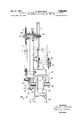
- FIG. 1 shows a lateral view, with some parts indicated diagrammatically, of a machine in accordance with the invention
- FIG. 2 is a section on enlarged scale on the line II-II in FIG. 1, with some parts removed for the sake of clarity;
- FIG. 3 is a section on line IIIIII of FIG. 7 on a larger scale than FIG. 1 showing the rotary member and auxiliary means for firing the tubes on to the valves, with the stages of arrival and departure of the valves and of the finished product removed;
- FIG. 4 is a section on line IVIV of FIG. 3;
- FIG. 5 is an enlarged detail of a tube about to be mounted on a valve
- FIG. 6 is a detail similar to FIG. 5, after mounting of the tube;
- FIG. 7 is a plan view of the machine.
- the machine illustrated in the attached drawing includes a framework 1 provided with legs 1A which support a coil 2 pivoted on supports integral with said framework, and from which unwinds a flexible tube 11 of plastic material intended for cutting by the machine itself into lengths each comprising a dip tube for an aerosol container.
- a flexible tube 11 of plastic material intended for cutting by the machine itself into lengths each comprising a dip tube for an aerosol container.
- Each tube is connected by the machine to an aerosol container valve.
- a flexible belt 6 passes over said pulleys 3, 4, 5, as shown especially in FIG. 1.
- the arrangement is such that when cog 7 rotates in a particular direction (indicated by F1 in FIGS. 1 and 2), the pulley 3 is forced to rotate in the same direction, while said pulley remains still when cog 7 rotates in the opposite direction.
- FIGS. 1, 2 indicate a chain which meshes along a certain arc with the teeth of cog 7. At one end (see FIGS. 1, 2), the chain 8 is affixed to a spring 9 retained in its turn on framework 1.
- An electric motor 105 supported by the same vframework 1 actuates a crank 10 (afiixed to the other end of chain 8) by means of a speed changer, e.g. with expansible pulleys 106, .107 provided with a control wheel 108, and by means of a reduction unit 1.10, e.g. a worm 111 and helical wheel 112, on whose shaft the crank 10 is keyed.
- a speed changer e.g. with expansible pulleys 106, .107 provided with a control wheel 108
- a reduction unit 1.10 e.g. a worm 111 and helical wheel 112
- crank 10 is preferably of the type wherein crank pin 113 can slide in a channel 114 by means of a screw 115 actuated by a knob 116, and housed in the body 117 of crank 10 as schematically shown in FIG. '2.
- the pulleys 4, 5 also rotate.
- the second phase wherein pulley 5 is still and hence also the belt 6 and pulleys 4, 5, the flexible tube 11 is not entrained.
- FIG. 13 indicates in general a rotating drum described in more detail below, and having a series of rigid tubes 14 integral with a Maltese cross 15; the drum is supported on the fixed framework by means of suitable bearings so as to be freely rotatable about its axis, relative to the framework (see FIGS. 1, 2, 3).
- a toothed wheel 118 which drives a wheel 120, by means of a chain 119, said wheel 120by means of a conical drive not shown in the drawings but diagrammatically represented at 121 in FIGS. 1, 2, 3driving a shaft which is integral with member 19, which can actuate the Maltese cross 15, by a member of teeth such that for each rotation thereof the drum rotates through an angle corresponding to the distance between two consecutive tubes 14.
- the drum 13 thus turns intermittently. Every time it steps, a tube 14 therefrom is aligned with the length of tube 11 which is leaving the pulley 5.
- the movements of the members described above are so controlled that each time a tube 14 rests in this position, a length of flexible dip tube 11 impelled by the rotation of pulley 3 enters the tube 14.
- Cutting means are also provided for separating the length of tube 11 entered into tube 14 from the rest of tube 11.
- This means (FIG. 3) comprises a circular blade 23 mounted on a shaft 122 idling in a seating disposed eccentrically in a socket 123 integral with one end of shaft 20'.
- pinion 124 which meshes with a wheel 125 affixed to framework 1.
- the blade 23 completes a revolution about the axis of shaft 20 at each rotation of the latter.
- the components are so disposed that when the drum 13 is still, the blade 23 enters a channel between the plate 126 fixed to and integral with framework 1 and the plate 127 at the end of rotary drum 13, thus cutting the tube 11 which has entered the tube 14 present at the cutting station.
- FIG. 3 shows in detail the construction of the drum 13 on a shaft 128 aflixed at the two ends to fixed plates 126,129.
- Plate 127 which carries a series of tubes 14 at equal intervals around its circumference, can rotate freely. At each release of the Maltese cross 15, each tube is carried into alignment with the aperture 130 in fixed plate 126 from which it receives the section of tube 11 cut by blade 23, and after a few releases it arrives above the aperture 131 which is connected by a conduit not shown in the drawing to a compressed air supply, also not shown.
- Plate 127 is integral with a tube 132 coaxial with shaft 128, said tube 132 carrying the Maltese cross 15 and also a sleeve 133 which is supported by bearings on the plate 134 integral with framework 1.
- a second plate 136 is integral with framework. 1 by means of members 135 and guides the end of a tubular prolongation 138 which is integral with tube 132.
- the cylinder 138 has axial channels 139 in continuation of tubes 14; a section of tube 11 driven by compressed air can thus travel through a tube 14 and a channel 139 when the latter is externally closed by an obturator bar 140 integral with the machine framework and shown diagrammatically in section in FIG. 4.
- valve of the aerosol or other container comprises an extension 142 having a frusto-conical portion 143.
- the smaller base of this portion has a diameter less than the internal diameter of tube 11, while the larger base of the same frustoconical portion has a diameter substantially greater than said tube diameter.
- the valve 141 is put into a position wherein the frusto-conical portion is coaxial with one of the grooves 139.
- the cylinder 138 terminates in a plate 144 provided with bearings 145 for rotating on shaft 128 and with recesses 146 adapted to hold the valves (FIGS. 37).
- the valves 141 (FIG. 7) are fed to the recesses 146 by one or more slideways 147 disposed downstream of the position where the lengths of tube are engaged.
- the valves are supplied by feeders known per se and not illustrated.
- the shaft 20 is supported by bearings 14 8 on plate 129. Beyond said plate the shaft 20 carries an eccentric 149 connected through a shaft 150 and joints 152 to a crank 151. This cran'k is afiixed to a rotary shaft 153 supported by plate 129. The shaft 153 projects beyond plate 129 and carries a pair of spaced arms 154, one just above and one just below the plate 144 (see FIG. '7).
- the operation of the machine is simple.
- the drum 13 moves at intervals, taking a tube 14 above the cutting station.
- a tube 11 is fed into tube 14 and cut.
- the plate 144 receives from slideways 147 valves 141 without tubes.
- the other tubes 14 are filled in correspondence with station A.
- a cam integral for instance with shaft 20, actuates a valve, also not illustrated, which connects the jet of compressed air to tube 14, firing the plastic tube 11 until it engages the extension 142 of valve 141.
- Apparatus for coupling dip tubes to extensions of valves for aerosol containers and the like comprising dip tube guide means adapted to be connected with a source of compressed air, support means for supporting in alignment with said guide means a valve having an extension to which a diptube is to be coupled, said guide means comprising a plurality of guide tubes in which dip tubes are guided and a structure formed with a plurality of grooves aligned respectively with said guide tubes for receiving the dip tubes therefrom and continuing the guiding of the dip tubes to a valve extension, means for intermittently rotating said structure and the guide tubes aligned with the grooves thereof past a series of stations one of which communicates with the source of compressed air so that a dip tube in a guide tube situated at said one station will be propelled by compressed air from the latter guide tube along a groove aligned therewith to an extension of a valve carried by said support means.
- dip tube guide means adapted to be connected with a source of compressed air
- support means for supporting in alignment with said guide means a valve having an extension to receive a dip tube propelled along said guide means by the compressed air
- feeding means for feeding a section of dip tube to said guide means
- said feeding means comprising a continuous belt, a wheel over which said belt extends, a rotary crank operatively connected with said belt for advancing the belt, release means for intermittently releasing the drive from said crank to said belt, and a spring operatively connected to said belt for returning the belt to an initial position when the connection of said crank to said belt is released by said release 15 means so as to transmit unidirectional movement of a desired magnitude to said belt from said crank by said release means.
Landscapes
- Chemical & Material Sciences (AREA)
- Dispersion Chemistry (AREA)
- Engineering & Computer Science (AREA)
- Mechanical Engineering (AREA)
- Containers And Packaging Bodies Having A Special Means To Remove Contents (AREA)
- Details Or Accessories Of Spraying Plant Or Apparatus (AREA)
Applications Claiming Priority (2)
| Application Number | Priority Date | Filing Date | Title |
|---|---|---|---|
| IT1912567 | 1967-08-02 | ||
| IT1223268 | 1968-01-31 |
Publications (1)
| Publication Number | Publication Date |
|---|---|
| US3609848A true US3609848A (en) | 1971-10-05 |
Family
ID=26326490
Family Applications (1)
| Application Number | Title | Priority Date | Filing Date |
|---|---|---|---|
| US747682A Expired - Lifetime US3609848A (en) | 1967-08-02 | 1968-07-25 | Apparatus for coupling dip tubes to extensions of valves for aerosol containers and the like |
Country Status (7)
| Country | Link |
|---|---|
| US (1) | US3609848A (de) |
| AT (1) | AT285299B (de) |
| CH (1) | CH483349A (de) |
| DE (1) | DE1775319B1 (de) |
| ES (1) | ES356721A1 (de) |
| FR (1) | FR1577012A (de) |
| GB (1) | GB1180010A (de) |
Cited By (2)
| Publication number | Priority date | Publication date | Assignee | Title |
|---|---|---|---|---|
| US3798736A (en) * | 1971-10-27 | 1974-03-26 | E Gibbons | Rubber stamp assembler |
| CN111702440A (zh) * | 2020-06-08 | 2020-09-25 | 刘海平 | 一种喷油嘴过滤网组合机 |
Families Citing this family (2)
| Publication number | Priority date | Publication date | Assignee | Title |
|---|---|---|---|---|
| GB2274422B (en) * | 1993-01-26 | 1995-06-14 | Guinness Brewing Worldwide | Method and apparatus for providing pieces of flexible material from a length thereof |
| US5636429A (en) * | 1994-01-31 | 1997-06-10 | Guiness Brewing Worldwide Limited | Method and apparatus for providing pieces of flexible material from a length thereof |
Family Cites Families (2)
| Publication number | Priority date | Publication date | Assignee | Title |
|---|---|---|---|---|
| DE1142227B (de) * | 1953-09-02 | 1963-01-10 | Abplanalp Robert H | Maschine zur mechanischen Verbindung eines vorzugsweise aus Kunststoff bestehenden Tauchrohrs mit dem Ventil-gehaeuse |
| US3015155A (en) * | 1957-04-16 | 1962-01-02 | American Can Co | Apparatus for assembling aerosol valves |
-
1968
- 1968-07-15 CH CH1056168A patent/CH483349A/it not_active IP Right Cessation
- 1968-07-25 FR FR1577012D patent/FR1577012A/fr not_active Expired
- 1968-07-25 US US747682A patent/US3609848A/en not_active Expired - Lifetime
- 1968-07-27 DE DE19681775319 patent/DE1775319B1/de active Pending
- 1968-07-31 ES ES356721A patent/ES356721A1/es not_active Expired
- 1968-08-02 GB GB36909/68A patent/GB1180010A/en not_active Expired
- 1968-08-02 AT AT756968A patent/AT285299B/de not_active IP Right Cessation
Cited By (2)
| Publication number | Priority date | Publication date | Assignee | Title |
|---|---|---|---|---|
| US3798736A (en) * | 1971-10-27 | 1974-03-26 | E Gibbons | Rubber stamp assembler |
| CN111702440A (zh) * | 2020-06-08 | 2020-09-25 | 刘海平 | 一种喷油嘴过滤网组合机 |
Also Published As
| Publication number | Publication date |
|---|---|
| DE1775319B1 (de) | 1972-05-25 |
| GB1180010A (en) | 1970-02-04 |
| ES356721A1 (es) | 1970-05-01 |
| CH483349A (it) | 1969-12-31 |
| FR1577012A (de) | 1969-08-01 |
| AT285299B (de) | 1970-10-27 |
Similar Documents
| Publication | Publication Date | Title |
|---|---|---|
| US2306018A (en) | Apparatus for making flexible tubing | |
| DK147632B (da) | Apparat til stopning af et foedevareprodukt i et roerformet hylster | |
| ZA904964B (en) | Procedure and apparatus for helical cutting of a flexible tubular sheet of polymeric material | |
| US3609848A (en) | Apparatus for coupling dip tubes to extensions of valves for aerosol containers and the like | |
| US3437114A (en) | Machine for making a wire cage | |
| US3756103A (en) | Apparatus for and method of trimming containers | |
| GB1396047A (en) | Winding machine for producing coil springs | |
| US1282609A (en) | Machine for loading cartridges. | |
| DE2317468A1 (de) | Verfahren und vorrichtung fuer das schneiden von langgestreckten gegenstaenden | |
| US2771725A (en) | Method of and apparatus for use in applying contractible bands to articles | |
| US2096605A (en) | Universal spring coiling machine | |
| US2835371A (en) | Collapsible tube handling mechanism | |
| US2999533A (en) | Apparatus for making bags | |
| US2521209A (en) | Work feeding mechanism for machine tools | |
| US3983772A (en) | Cutting machine | |
| US2792869A (en) | Wire coiling machine having an accurate wire feeding mechanism | |
| US3350255A (en) | Tape-wrapping machine | |
| US3172705A (en) | Feed means for soldering apparatus | |
| SE446438B (sv) | Anordning for flerstrengsvetning av tva roterande arbetsstycken | |
| US3122977A (en) | Graham | |
| US4317546A (en) | Coiling apparatus for fastener strips | |
| US531616A (en) | Can-testing machine | |
| US2230410A (en) | Method and apparatus for making hollow bodies | |
| CN209335677U (zh) | 一种自动牵引切管装置 | |
| US3757651A (en) | Apparatus for advancing and retracting a dispenser body to and from a bag applicator |