US3596901A - Sheet separator - Google Patents
Sheet separator Download PDFInfo
- Publication number
- US3596901A US3596901A US819712A US3596901DA US3596901A US 3596901 A US3596901 A US 3596901A US 819712 A US819712 A US 819712A US 3596901D A US3596901D A US 3596901DA US 3596901 A US3596901 A US 3596901A
- Authority
- US
- United States
- Prior art keywords
- delivery
- transfer belt
- stack
- belt
- sheets
- Prior art date
- Legal status (The legal status is an assumption and is not a legal conclusion. Google has not performed a legal analysis and makes no representation as to the accuracy of the status listed.)
- Expired - Lifetime
Links
- 238000000926 separation method Methods 0.000 claims description 4
- 230000004888 barrier function Effects 0.000 description 3
- 239000011248 coating agent Substances 0.000 description 3
- 238000000576 coating method Methods 0.000 description 3
- 230000007257 malfunction Effects 0.000 description 3
- 230000006978 adaptation Effects 0.000 description 2
- 244000043261 Hevea brasiliensis Species 0.000 description 1
- 239000004677 Nylon Substances 0.000 description 1
- 229920001971 elastomer Polymers 0.000 description 1
- 239000004744 fabric Substances 0.000 description 1
- 238000000034 method Methods 0.000 description 1
- 238000012986 modification Methods 0.000 description 1
- 230000004048 modification Effects 0.000 description 1
- 229920003052 natural elastomer Polymers 0.000 description 1
- 229920001194 natural rubber Polymers 0.000 description 1
- 229920001778 nylon Polymers 0.000 description 1
- 239000004033 plastic Substances 0.000 description 1
- 229920003023 plastic Polymers 0.000 description 1
- 229920002635 polyurethane Polymers 0.000 description 1
- 239000004814 polyurethane Substances 0.000 description 1
- 230000000284 resting effect Effects 0.000 description 1
- 230000000979 retarding effect Effects 0.000 description 1
- 239000005060 rubber Substances 0.000 description 1
- 229920003051 synthetic elastomer Polymers 0.000 description 1
- 239000005061 synthetic rubber Substances 0.000 description 1
Images

Classifications
-
- B—PERFORMING OPERATIONS; TRANSPORTING
- B65—CONVEYING; PACKING; STORING; HANDLING THIN OR FILAMENTARY MATERIAL
- B65H—HANDLING THIN OR FILAMENTARY MATERIAL, e.g. SHEETS, WEBS, CABLES
- B65H3/00—Separating articles from piles
- B65H3/02—Separating articles from piles using friction forces between articles and separator
- B65H3/04—Endless-belt separators
- B65H3/042—Endless-belt separators separating from the bottom of the pile
-
- B—PERFORMING OPERATIONS; TRANSPORTING
- B65—CONVEYING; PACKING; STORING; HANDLING THIN OR FILAMENTARY MATERIAL
- B65H—HANDLING THIN OR FILAMENTARY MATERIAL, e.g. SHEETS, WEBS, CABLES
- B65H2701/00—Handled material; Storage means
- B65H2701/10—Handled articles or webs
- B65H2701/19—Specific article or web
- B65H2701/1912—Banknotes, bills and cheques or the like
Definitions
- This invention relates to a device for individually removing sheets, one by one, from a stack, and more particularly to such a device in which a moving transfer belt engages one surface of a sheet on the end of a stack to remove it therefrom, while the convexly curved stripper engages the opposite surface of sheets in the stack to retard removal of adjacent sheets and thus separate the end sheet from the adjacent sheets.
- the stripper of this device is a roller provided with a friction coating. A portion of the roller projects through a slot in a guide plate, and the roller is driven slowly in a direction opposite to the direction in which the transfer belt moves.
- the frontal drive roller for the transfer belt is positioned opposite the stripping roller.
- the operating range within which the transfer belt and the stripping roller can cooperate with each other to separate the end sheet from the adjacent sheets in the stack is relatively short. In this device separation of the end sheet from the stack may fail to occur particularly if the sheets are of uneven configuration or are deformed, as for example by being crumpled, limp, or torn. It is also possible that a number of sheets may become wedged together at a discharge point so that manual removal of the wedged sheets is necessary before operation ofthe apparatus can be resumed.
- a stripping surface having a convex curvature is provided at the discharge point of the stack and that the drive roller pulling the transfer belt is so disposed adjacent said discharge point that the transfer belt is looping about said stripping surface.
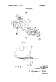
- FIG. I is a schematic side view of one embodiment of the present invention.
- FIG. 2 is an enlarged view ofa portion of FIG. 1 illustrating a particular operating situation.
- FIG. 3 is a section along the line III-III of FIGURE ll.
- FIG. 4 is a section along the line lV--IV ofFIGURE 1.
- FIG. 5 is a schematic side view of another embodiment of the invention.
- a stack 31 of bills 1 is vertically arranged with the underside of the lowermost bill 32 resting upon a portion of the outer surface 3d of the forward reach ofa transfer belt 2.
- a rigid and nonrotatable cylindrical disc 3 whose outer surface 3 is formed so as to have a higher coefficient of friction than that between adjacent sheets ofa stack.
- a support roller 4 which rotates about a fixed axis to support the rear portion of the forward reach of transfer belt 2 and the stack and a tension roller 5 which is mounted for longitudinal movement in a support 6.
- the end of transfer belt 2 is looped about the tension roller 5.
- a weight 8 acts on tension roller 5 via a cable 7 which is entrained about a guide roller 7 and pulls the belt 2 so as to maintain it under constant tension.
- the other end, i.e. the front end of the forward reach of transfer belt 2 is looped about a drive roller 9.
- the coefficient of friction between the surface of transfer belt 2 and the sheets is higher than that between said surface 3 and the sheets.
- Drive roller 9 is so positioned relative to the stripper disc 3 and the guide roller 4 of the transfer belt 2 that the transfer belt is in contact with the stripper surface through an angle of approximately 60.
- drive roller 9 is fixed on a drive shaft 10 which is pivoted on support structure 45.
- Two freely rotatable guide rollers 17 are rotatably mounted on the shaft 10 on each side of the drive roller 9.
- a conveying belt 18 is entrained about each of the guide rollers 17, and the belts together serve as a delivery belt for sheets received from the transfer belt 2.
- FIG. 4 the same shows further details of the stripper disc 3 and associated structure.
- Disc 3 is rigidly mounted on a shaft 19 which is rigidly secured to support structure 40.
- a friction surface 3' is formed on the circumference of disc 3.
- Freely rotatable guide rollers 20 are rotatably mounted on shaft 19 on each side of the disc 3.
- Guide rollers 20 have a lesser diameter than the disc 3.
- a delivery belt 21 is entrained about each of the guide rollers 20 and thereafter entrained so that its outer surface 4 0 is in contact with the outer surface 42 of delivery belt 1% as the belts pass along about guide rollers 17.
- the lower run 43 of the delivery belt 21 moves in contact with the upper run ll of belt 118 so that a sheet, once delivered between belts 18 and 21 by the transfer belt 2, is thereafter carried along to a further destination.
- Delivery belts 18 and .21 are driven via appropriately arranged drive rollers 23 and 2A, which are illustrated in connection with the FIG. 5 embodiment and are independent of the drive of the drive roller 9 of the transfer belt 2.
- a photoelectric barrier 25/25 is arranged adjacent the beginning of the cooperating runs of the delivery belts 18 and 21 so that it responds to the passage of the front edge of a bill I pulled out of the stack by a transfer belt 2 through the barrier.
- An appropriate control signal is then supplied through a drive control circuit Ml which then stops the drive roller 9 of the transfer belt until the next call for a bill.
- the delivery conveyor belts 18 and 21, however, continue their movement to carry the bill to its further destination, after which they may be stopped, although this is not relevant to the invention disclosed in this application.
- a plate 26 having a lesser coefficient of friction than the friction surface 3 is vertically arranged and is tangential to disc 3 on the side facing the stack. It provides a guide for the front edge of the stack of bills 1.
- FIG. 5 a different embodiment of the apparatus for maintaining tension on the transfer belt 2 is shown.
- the apparatus is generally similar to that of FIG. 1 and corresponding parts have corresponding reference numerals.
- the drive roller 9 and the support roller 4 of the transfer belt 2 are mounted for rotation about fixed axes.
- roller 5' unlike the tension roller 5 of the FIG. ll embodiment is not movably mounted, but also rotates about a fixed axis and serves as an additional support roller for the transfer belt 2.
- the loose reach 41-6 of the transfer belt 2 which extends along its lower run is biased downwardly by a tension ing arm 13 having a sliding guide 13' fastened thereto.
- Arm 13 is fixed to a disc 12 which is rotatable around an axis Ill, and is biased into the tensioning position by a spring 16 which is secured to the disc 12 at 12' and to fixed support structure 15.
- the arrangement of these elements is such that, as is also true in the embodiment illustrated in FIG. 1, the belt tension is substantially independent of the position of the transfer belt.
- the stripper disc 3 was 95 mm. in diameter, the roller 9 56 mm. in diameter, the rollers 4 and 5 were 40 mm. in diameter.
- the rollers were each made of nylon plastic, roller 9 having a coating of natural rubber.
- Transfer belt 2 was l5 mm. in width and 580 mm. long.
- Vulcollan is an elastomeric polyurethane.
- the surface which were finished by grinding had a coefficient of friction of 0,5...0,6 to paper of the kind involved.
- Transfer belt 2 were made of fabric coated with synthetic rubber and sold by the VIS-Kunststoffwerk Offenburg under the designation model number C 10 in one version and B 08 in another version. A coefficient of friction of 0,7... 0,9 to paper were measured. The loose reach 46 of transfer belt 2 was held under a tension of about 180 p (Pond). All other belts were made from pure rubber.
- the drive control means 44 When it is desired to deliver a bill I from the stack 31, the drive control means 44 is selectively operated. Drive roller 9 is rotated and transfer belt 2 then pulls the lowermost bill 32 out of the stack and carries it into the region between the delivery conveying belts 18 and 21. These belts then engage the bill therebetween and pull it for delivery to a further point. As soon as the front edge of the bill reaches the light barrier 25/25, a signal is supplied to the drive control means 44 and drive roller 9 of the transfer belt 2 is stopped. The delivery belts l8 and 21 continue to move to completely pull the bill out of the separator device and to bring it to its further destination. Thereafter, they are also automatically stopped.
- the enclosure results in an increased belt tension in the pulling reach.
- the bills are pressed closer to the transfer belt and into the stripping surface.
- Both the forward pushing force exerted by the transfer belt 2 on the lowermost bill 32 and the retarding force exerted by the stripper surface 3 on the upper surface of the uppermost bill is increased.
- the absolute value of the differential force on these bills increases until finally the frictional force between the bills is markedly exceeded and separation is accomplished.
- FIG. 2 shows a situation in which a number of bills I have advanced between a portion of the stripping surface 3 and the belt 2. Since the belt tension in the loose reach is maintained constant, the play of forces is not interfered with during the removing process and is independent of the fact whether or not the transfer belt is deflected to a greater or lesser degree.
- apparatus for separating sheets from a stack which apparatus includes rotatably mounted transfer belt means having a forward reach for removing individual sheets from the stack, delivery means for receiving each sheet removed from the stack by said belt means and for delivering the sheets to a receiving point, means defining a convex stripping surface adjacent the outlet end of said apparatus, support roller means supporting the rear portion of said forward reach, and drive roller means supporting the front end of the forward reach of said transfer belt means for moving said belt means in a direction to convey sheets from the stack to said delivery means, said belt means having a loose return reach arranged to move in the opposite direction, said drive roller means being positioned for causing said forward reach to be urged against and conform to the shape of, said stripping surface along a portion of its length which subtends an angle of more than about 25, the improvement wherein said portion of the length of said forward reach which conforms to the shape of said stripping surface is spaced from the parts of said forward reach which bear against said support roller means and said drive roller means, said forward reach of said transfer belt means constitutes the
- said delivery means includes delivery belt means and drive means for driving said delivery belt means
- said apparatus further comprises: means for sensing the delivery of a sheet from the transfer belt to the delivery belt means, means responsive to said sensing means for stopping said drive roller of the transfer belt means while said drive means of the delivery belt means continues to operate, and means for starting the drive roller of said transfer belt means when the delivery ofa new sheet is desired.
Landscapes
- Engineering & Computer Science (AREA)
- Mechanical Engineering (AREA)
- Delivering By Means Of Belts And Rollers (AREA)
- Separation, Sorting, Adjustment, Or Bending Of Sheets To Be Conveyed (AREA)
- Pile Receivers (AREA)
- Sheets, Magazines, And Separation Thereof (AREA)
Applications Claiming Priority (1)
| Application Number | Priority Date | Filing Date | Title |
|---|---|---|---|
| DE19691914839 DE1914839B2 (de) | 1969-03-24 | 1969-03-24 | Einrichtung zum vereinzeln von blaettern von einem stapel |
Publications (1)
| Publication Number | Publication Date |
|---|---|
| US3596901A true US3596901A (en) | 1971-08-03 |
Family
ID=5729086
Family Applications (1)
| Application Number | Title | Priority Date | Filing Date |
|---|---|---|---|
| US819712A Expired - Lifetime US3596901A (en) | 1969-03-24 | 1969-04-28 | Sheet separator |
Country Status (6)
| Country | Link |
|---|---|
| US (1) | US3596901A (de) |
| AT (1) | AT292345B (de) |
| CA (1) | CA925891A (de) |
| DE (1) | DE1914839B2 (de) |
| GB (1) | GB1279206A (de) |
| SE (1) | SE376988B (de) |
Cited By (2)
| Publication number | Priority date | Publication date | Assignee | Title |
|---|---|---|---|---|
| US3895791A (en) * | 1973-03-19 | 1975-07-22 | Xerox Corp | Bottom sheet feeder using separation belt and retard pad |
| US3934869A (en) * | 1973-12-20 | 1976-01-27 | Xerox Corporation | Sheet separating and feeding apparatus |
Families Citing this family (2)
| Publication number | Priority date | Publication date | Assignee | Title |
|---|---|---|---|---|
| DE2356071C3 (de) * | 1973-11-09 | 1984-05-03 | Zuber, geb. Ruthingsdorfer, Anna Katharina, 8510 Fürth | Vorrichtung zur Außenbearbeitung von Grafit-, Farb-, Kosmetikstiften o.dgl. |
| DE3447236A1 (de) * | 1984-12-22 | 1986-07-03 | Professor Alfred Krauth Apparatebau GmbH & Co KG, 6930 Eberbach | Ausgeber fuer einzelausgabe von banknoten |
Citations (4)
| Publication number | Priority date | Publication date | Assignee | Title |
|---|---|---|---|---|
| US1011820A (en) * | 1907-06-21 | 1911-12-12 | Elie W Labombarde | Mechanism for feeding blanks, sheets, and the like. |
| US2273288A (en) * | 1941-02-05 | 1942-02-17 | Pitney Bowes Postage Meter Co | Adjustable separator |
| US3239213A (en) * | 1964-01-02 | 1966-03-08 | Xerox Corp | Document feeder |
| US3288461A (en) * | 1964-12-28 | 1966-11-29 | Xerox Corp | Sheet feeding apparatus |
-
1969
- 1969-03-24 DE DE19691914839 patent/DE1914839B2/de not_active Withdrawn
- 1969-04-28 US US819712A patent/US3596901A/en not_active Expired - Lifetime
-
1970
- 1970-03-13 AT AT238270A patent/AT292345B/de not_active IP Right Cessation
- 1970-03-20 CA CA077962A patent/CA925891A/en not_active Expired
- 1970-03-23 GB GB03823/70A patent/GB1279206A/en not_active Expired
- 1970-03-24 SE SE7004064A patent/SE376988B/xx unknown
Patent Citations (4)
| Publication number | Priority date | Publication date | Assignee | Title |
|---|---|---|---|---|
| US1011820A (en) * | 1907-06-21 | 1911-12-12 | Elie W Labombarde | Mechanism for feeding blanks, sheets, and the like. |
| US2273288A (en) * | 1941-02-05 | 1942-02-17 | Pitney Bowes Postage Meter Co | Adjustable separator |
| US3239213A (en) * | 1964-01-02 | 1966-03-08 | Xerox Corp | Document feeder |
| US3288461A (en) * | 1964-12-28 | 1966-11-29 | Xerox Corp | Sheet feeding apparatus |
Cited By (2)
| Publication number | Priority date | Publication date | Assignee | Title |
|---|---|---|---|---|
| US3895791A (en) * | 1973-03-19 | 1975-07-22 | Xerox Corp | Bottom sheet feeder using separation belt and retard pad |
| US3934869A (en) * | 1973-12-20 | 1976-01-27 | Xerox Corporation | Sheet separating and feeding apparatus |
Also Published As
| Publication number | Publication date |
|---|---|
| AT292345B (de) | 1971-08-25 |
| CA925891A (en) | 1973-05-08 |
| DE1914839A1 (de) | 1971-06-16 |
| SE376988B (de) | 1975-06-16 |
| DE1914839B2 (de) | 1972-01-13 |
| GB1279206A (en) | 1972-06-28 |
Similar Documents
| Publication | Publication Date | Title |
|---|---|---|
| US4991831A (en) | Paper sheet feeding apparatus | |
| US3469834A (en) | Sheet feeder and separator apparatus | |
| US5143365A (en) | Paper sheet feeding apparatus | |
| US4216952A (en) | Feed mechanism for sequentially separating documents, sheets, coupons and the like | |
| US3966193A (en) | Mail handling stacking and feeding apparatus | |
| US3506258A (en) | Document feeding mechanism | |
| US5098078A (en) | Continuous paper let-out apparatus | |
| US5642877A (en) | Paper sheet feeding apparatus and gate forming member therefor | |
| US2853298A (en) | Jogger mechanisms | |
| US4039180A (en) | Sheet feeding apparatus | |
| US4928944A (en) | High speed sheet feeder singulator | |
| US3838851A (en) | Bottom sheet feeder | |
| US3869117A (en) | Flat-article separating apparatus for an automatic mail handling system and the like | |
| JPS583940B2 (ja) | シ−トオクリダシソウチ | |
| US2764409A (en) | Method and apparatus for friction feeding of sheets | |
| US4478400A (en) | Envelope feeder for a duplicating press | |
| US3596901A (en) | Sheet separator | |
| US4204667A (en) | Semi-circular stack sheet feeding apparatus | |
| US2023531A (en) | Apparatus for feeding sheets to folding machines | |
| US6053492A (en) | Apparatus for sequentially feeding cards to inserter in a magazine binding line | |
| SE462089B (sv) | Inmatningsanordning foer arkformiga objekt, fraemst sedlar, med hjaelp av ett aendloest band foersett med griporgan i form av flappar | |
| US2907567A (en) | Article feeding apparatus | |
| US3709482A (en) | High speed document feeder | |
| JPH0238506B2 (ja) | Fukushakinoyoshikyokyusochi | |
| US5794930A (en) | Apparatus for feeding the gathering segment of a gather-stitcher |