US3563533A - Copy sheet supply device - Google Patents
Copy sheet supply device Download PDFInfo
- Publication number
- US3563533A US3563533A US818700A US3563533DA US3563533A US 3563533 A US3563533 A US 3563533A US 818700 A US818700 A US 818700A US 3563533D A US3563533D A US 3563533DA US 3563533 A US3563533 A US 3563533A
- Authority
- US
- United States
- Prior art keywords
- roller
- clutch
- disc
- sheet
- switch
- Prior art date
- Legal status (The legal status is an assumption and is not a legal conclusion. Google has not performed a legal analysis and makes no representation as to the accuracy of the status listed.)
- Expired - Lifetime
Links
- 230000002093 peripheral effect Effects 0.000 claims description 31
- 230000033001 locomotion Effects 0.000 claims description 18
- 230000008878 coupling Effects 0.000 claims description 14
- 238000010168 coupling process Methods 0.000 claims description 14
- 238000005859 coupling reaction Methods 0.000 claims description 14
- 230000005540 biological transmission Effects 0.000 claims description 4
- 230000005284 excitation Effects 0.000 claims description 4
- 230000004044 response Effects 0.000 claims description 3
- 230000001960 triggered effect Effects 0.000 claims description 3
- 230000004323 axial length Effects 0.000 claims description 2
- 230000008859 change Effects 0.000 claims description 2
- 238000003780 insertion Methods 0.000 claims description 2
- 230000037431 insertion Effects 0.000 claims description 2
- 239000000306 component Substances 0.000 description 13
- 230000009471 action Effects 0.000 description 7
- 230000007246 mechanism Effects 0.000 description 5
- 238000010586 diagram Methods 0.000 description 3
- 239000003990 capacitor Substances 0.000 description 2
- 230000001419 dependent effect Effects 0.000 description 2
- 230000009347 mechanical transmission Effects 0.000 description 2
- 230000003321 amplification Effects 0.000 description 1
- 230000008901 benefit Effects 0.000 description 1
- 238000006073 displacement reaction Methods 0.000 description 1
- 230000000694 effects Effects 0.000 description 1
- 238000007786 electrostatic charging Methods 0.000 description 1
- 238000005286 illumination Methods 0.000 description 1
- 238000003199 nucleic acid amplification method Methods 0.000 description 1
- 230000036962 time dependent Effects 0.000 description 1
Images


Classifications
-
- G—PHYSICS
- G03—PHOTOGRAPHY; CINEMATOGRAPHY; ANALOGOUS TECHNIQUES USING WAVES OTHER THAN OPTICAL WAVES; ELECTROGRAPHY; HOLOGRAPHY
- G03G—ELECTROGRAPHY; ELECTROPHOTOGRAPHY; MAGNETOGRAPHY
- G03G15/00—Apparatus for electrographic processes using a charge pattern
- G03G15/65—Apparatus which relate to the handling of copy material
- G03G15/6502—Supplying of sheet copy material; Cassettes therefor
Definitions
- the invention is more particularly concerned with sheet supply devices for feeding copy sheets from a stack by means of a pickoff device to conveyor means for the copy sheets in dependence on the introduction of an original to be copied, the sheet supply device comprising a first switch positioned in the path of the original and arranged to deliver a pulse signal upon tripping of the switch, a second switch positioned in the feed path of the copy sheets and arranged to deliver a pulse signal in dependence on the delivery of a copy sheet into a ready position, a drive coupling comprising a disc having a peripheral recess and a continuously driven drive roller, said drive roller being arranged to rotate in said peripheral recess 'without contact with the disc but outside the recess drivingly engaging the periphery of thedisc, spring means biasing said disc towards said roller, and stop means the release of which by tripping of said switches produces said engagement between the disc and roller due to the action of said spring means.
- a counter mechanism for establishing or controlling the number of copies can be added extremely easily.
- an actuating mechanism for said stop means is provided which is selectively releasable by said two switches respectively associated with the original and with the copy sheets in order to produce a limited time engagement of a clutch arranged to initiate movement of the pickoff device for the copy sheets, wherein the pickoff device for the copy sheets has a different sheet transport speed than subsequent conveyor means for the copysheets, and wherein a slipping clutch which is operative in dependence on the speed differential is provided between the intermittently operating sheet pickoff device and said conveyor means.
- the drive coupling includes a stop plate and an associated stop lever which is actuated in dependence on the pulses delivered by the switches positioned in the paths of the original and of the copy sheets.
- the stop plate has two steps formed in its peripheral surface 180 apart, said spring means urge the disc having the peripheral recess into engagement with its associated continuously rotating drive roller after release of the stop plate, and the stop plate is also provided with cam means arranged to trigger the release of a controlled feed roller combination for advancing the copy sheets.
- the controlled feed roller combination for advancing the copy sheets comprises a first continuously rotating roller and a second roller provided with a flat peripheral portion which is arranged to engage the continuously rotating roller when the flat portion is moved towards said first roller by spring means, and locking means including a lever are provided between said second roller and the stop plate, said locking means being disengaged by release of the stop plate.
- a clutch is provided between continuously rotating drive means and a drive connection for the copy sheet pickoff device, said clutch being operative in dependence on reversal of one of the switches which are positioned in the paths of the original and of the copy sheets.
- a changeover switch is provided between the trip switches for the original and for-the copy sheets and is connected to an actuating magnet for the drive coupling, and an actuating member for triggering this changeover switch is connected to said drive coupling which connects the main drive to the sheet pickoff device.
- the pickofl device for the copy sheets preferably comprises a friction pickoff roller rotating above a stack of sheets and connected to the intermittently rotating roller which has the flat peripheralportion and which is engageable with the drive roller.
- a slipping clutch is positioned between the pickoff roller and the continuously rotating roller.
- the slipping clutch which is a special component of the sheet supply device, comprises a first continuously driven gear wheel and a second gear wheel which is axially movable relative to the first gear wheel and which is movable back and forth relative to a stop on a shaft carrying the pickoff roller for the copy sheets. In this way time-dependent and drive-dependent control is achieved.
- a clutch having two halves which cooperate through two opposed inclined surfaces adjacent to opposed meshing steps, one of said clutch halves by spring action and by means of the changeover switch providing a connection between the trip switches associated with the original and with the copy sheets and also effecting a connecting for actuating the drive coupling between the continuously rotating drive and the copy sheet pickoff device.
- the stop plate having two steps apart has its associated stop lever preferably actuated by a magnet which is energized by pulses delivered via the trip switches in the paths of the original and of the copy sheets.
- the stop plate preferably includes a cam operative on one end of a double-armed lever which at its other end is engageable with the flattened roller for feeding the copy sheets, this latter'roller being freed after release of the stop plate by the passage of the original until the cycles ends as the next copy sheet is supplied.
- FIG. 1 is a block schematic diagram representing a sheet supply device in accordance with the invention
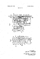
- FIG. 2 is a plan view of a part of an actual embodiment of the sheet supply device shown schematically in FIG. 1;
- FIG. 3 is a side elevation of the device of FIG. 2 taken along the line III-III of FIG. 2;
- FIG. 4 is a front elevation of part of the device shown in FIG. 2;
- FIG. 5 is an electrical circuit diagram for the sheet supply device shown in FIGS. 1 to 4;
- FIG. 6 is a part view of a clutch with its halves in a first operative position, the clutch also being shown in FIG. 2;
- FIG. 7 is a view of the clutch shown in FIG. 6 but with its halves in a second operative position
- FIG. 8 is a side vie of a copying machine shown in diagrammatic form to explain the relation ship of the copy sheet supply device of the invention to the rest of the machine.
- FIG. 8 A copying machine is shown in FIG. 8 comprising a housing 101. Supporting frame members are provided within the housing 10] parallel to thesidewalls thereof, i.e., parallel to the plane of the drawing, as shown for example in FIGS. 2 and 4 at 33. In addition, mountingplates are provided within the housing, as shown at 54 and 55 in FIG. 2, the various components being secured to these plates or being supported thereby.
- the copying machine which is shown by way of example only, has an exposure plate or scanning 'window 102 in the top cover of the housing 101, and this plate 102 is illuminated by a pair of light sources 103 and 104.
- the light image is transmitted by a reflector 105 and along a projection tunnel 106, in which a lens arrangement 107 may be provided, to an exposure plate or window 108 in the path of the copy sheets.
- the copy sheets are arranged in a stack 109 on which, as will be described in more detail later, a frictional pickup roller 26 rests and adjacent to which a controlled pair of feed rollers 30 and 31 is provided, the roller 30 being continuously driven, while the roller 31 which is provided with a flat surface over part of its circumference is driven intermittently by means of a mechanism which will also be described later in order to supply the copy sheets to subsequent conveyor means 18.
- a switch 8 which is arranged to be actuated by the copy sheets and which includes a trip arm 110 which projects into the path of the copy sheets and which when tripped by a sheet initiates a predetermined response action.
- this switch 8 as is indicated in FIG. 3 by broken lines, is fitted into a peripheral slot in a counter pressure roller 35 also provided with a flat peripheral portion, so that the trip arm 110 is located in the region between the two feed rollers 30 and 31.
- a similar switch 2 corresponding to the switch 8 is provided in the path of movement of the original which is fed to the exposure plate 102 in the top of the housing 101 in the direction indicated by the arrow 1. This feed movement of the original is effected by pairs of driven transport rollers 111 and 112.
- the copy sheets pass to a processing unit 113, for example an electrostatic charging device, and from there they are carried on a guide 114 which pilots the copy sheets to the exposure plate 108 which has a backing plate 115 associated therewith.
- a processing unit 113 for example an electrostatic charging device
- pairs of cooperating guide rollers 116 and 117 are mounted above and below the plates 108 and 115.
- These guide rollers 116, 117 are hereinafter included when general reference is made to the conveyor means such as indicated at 18 in FIG. 1.
- a further guide 119 carries the copy sheets to a pair of cooperating transport rollers 120, and thereafter the sheets pass to a further processing unit 121, for example a developing bath.
- a further guide 122 then carries the copy sheets through for example a radiant heater 123 to fuse or dry the image. This guide 122 cooperates with a delivery roller 124 which passes the copy sheets to a delivery chute 125.
- the main drive means are indicated schematically by reference numeral 126 in FIG. 8 and by reference numeral 12 in FIG. 1.
- Driving connections 127, 128, 19 (see also FIG. 1), 129 and 130 extend from the drive means 126 to provide links with the driven components.
- the drive means 126 includes gearing, a motor with the necessary switching controls, the other usual components.
- the present invention is concerned particularly with the copy sheet supply device which, as in the schematic representation in FIG. 1, is also indicated in FIG. 8 by the reference numeral 6 and is there shown by the broken lines in its local position. It should be noted that a drive wheel 32 is included in the sheet supply device and is driven through the gear coupling 131 (FIG. 8).
- the original i.e., the master to be copied, moves as indicated by the arrow 1 into contact with the trip switch 2 which is positioned in its path and which upon actuation completes an electrical circuit connection to DC pulse source 3 so that a pulse is fed over a circuit line 4 to a changeover switch 5.
- the copy sheet is effectively supplied by the supply device 6 which is effective to withdraw the uppermost sheet of a stack of sheets.
- the copy sheet then follows a path 60 as indicated in FIG. 1 in the direction of the arrow 7 towards the trip switch 8 which in its function corresponds to the switch 2 and which when triggered makes an electrical circuit connection between a DC pulse source 9 and the changeover switch 5.
- This changeover switch completes an excitation circuit for a control magnet 10 each time one or other of the switches 2 and 8 is tripped, and the magnet 10 then causes the engagement of a clutch I11, i.e., a multiplier clutch, for a predetermined period of time.
- the clutch 11 receives its drive from the main drive 12 of the copying machine, this drive movement being fed to a further clutch 14 both via the clutch 11 and a via a parallel path through a gear transmission 13.
- This clutch 14, which may be considered to be engaged, further transmits the drive to a slipping clutch 15 which has a certain idle motion and which drives the copy sheet supply device 6.
- the clutch 11 also has a mechanical drive connection 16 to a controlled feed roller combination 17 for delivering the copy sheets, and this feeds the copy sheets to the conveyor means 18.
- the conveyor means 18 may be for example a combination of transport rollers and belts driven through a mechanical transmission 19 from the main copying machine drive 12.
- An important feature of the invention is that between the multiplier clutch l1 and the changeover switch 5 there is provided a mechanical connection 20 which selectively reverses the changeover switch.
- circuit lines 21 and 22 represent electrical connections, while the circuit lines 23, 24, 25 and 132 represent mechanical connections.
- the copy sheet supply device of the present invention is actuated from a single drive unit electrically controlled through two paths, i.e., by the switches 2 and 8, and is mechanically driven from the main drive 12 by the engaging of a slipping clutch 15 which is in series connection with a number of other clutches, and with a mechanical gear transmission 20 providing feedback in the electrical circuit in order to effect the necessary switching functions which ensure effectively controlled operation.
- the mechanical series connection 25 between the slipping clutch 15 and the clutch 14 is of particular im' portance. It is pointed out that the clutch 14 is driven from the main drive 12 and furthermore the multiplier clutch 11 provides feedback through the mechanical transmission 20 to the changeover switch 5 bypassing the magnet 10.
- the circuit path 24 provides a mechanical connection to the clutch 14 from the clutch 11 and the copy sheet supply device 15, 6 is driven from the clutch 14 through the circuit connection 25;
- the controlled feed roller combination 17 is actuated via the mechanical drive connection 16 to undergo one or more revolutions which causes a copy sheet to be fed to the conveyor means 18;
- the mechanical feedback coupling 20 is provided between the clutch l1 and the changeover switch 5 in order to be able to set the switch to a given state.
- the copysheet supply device 6 is positioned in the path of the copy sheets.
- the copy sheet supply device includes the friction pickup roller 26 which rests on the uppermost sheet of the stack of copy sheets.
- the roller 26 is mounted on a shaft 27 mounted in a pivotable stirrup 28 which is rotatable about a shaft 29 which also drives the continuously rotating feed roller 30 which has the control roller 31 associated therewith.
- the feed roller 30 and the control roller 31 are positioned in front of the stack of sheets on the ,uppermost of which the friction pickup roller 26 rests.
- shaft 29 extends through a housing frame 33 and has the drive wheel 32 mounted at its end.
- Thedrive wheel 32 is continuously driven in a manner not shown in further detail.
- the feed control roller 31 is mounted on a shaft 34 which, as shown in FIG. 4, lies beneath the shaft 29 and carries a clutch wheel 35 in nonrotational assembly therewith.
- FIG. 2 and also FIG. 4 show only the arrangement at one side of the sheet supply device, i.e., at
- rollers are correspondingly mounted at the other side of the housing in a frame similar to the frame 33, and likewise at the other side of the housing there is provided a pivotable stirrup for the friction pickup roller 26. Beneath the friction pickup roller 26 lies the uppermost sheet of the stack 109, as mentioned above in connection with FIG. 8.
- a gear wheel 36 is secured to the'shaft 29 and meshes with a clutch gear wheel 37. Also secured to the shaft 29 is a pair of gear wheels 38, 39 which are connected by a sleeve 40 and are rotatable relative to the shaft 29.
- the gear wheel 38 meshes with a toothed rim of the other half 41 of the clutch 37, 41 which is indicated in FIG. 1 by the reference numeral 14.
- a spring 42 is positioned between the gear wheels 36 and 38 and acts to urge them apart.
- the gear wheel 38 has a width which exceeds that of the clutch gear wheel 41 in order to ensure meshing engagement in the event of displacement of the com ponent group 38, 39, 40.
- an actuating lever 43 which is fixedly mounted on the one half 44 of a control clutch 44, 45 whose other half 45 is mounted on a wheel 46 which, as shown in FIG. 3, has two peripheral recesses 47 and 98.
- a drive wheel 48 is rotatable with the clutch gear wheel 37 on its shaft 49 and engages in said peripheral recesses 47, 98.
- the clutch halves 44 and 45 each have a step 50, 51 in their opposing faces. These steps are offset from each other in the initial position of the clutch. From these steps extend inclined surfaces, one of which is shown in FIG. 2 by reference numeral '52.
- the clutch half 44 is subject to the influence of a spring 53 which is seated at its other end against a frame member 54.
- FIG. 2' A similar associated frame member55 is also indicated in FIG. 2'.
- the frame members 54, 55 serve to support the various components.
- the spring 53 urges the clutch portion 44 towards the clutch portion 45, with the result that there is an axial movement of the clutch half 44 due to the spring 53 when the two halves interlock. In consequence there is a pivot movement of the lever 43 about a pivot pin 56 and meshing engagement of the clutch 41, 37 takes place.
- the wheels 46 and 48 forming a clutch in combination with the components 65 and 70 associated therewith and which will now be described, together correspond to the clutch 11 of FIG. 1, while the two feed rollers 30 and 31 correspond to the controlled feed roller combination 17 of FIG. 1.
- the actuating magnet shown in FIG. 1 which corresponds to the magnet indicated by the same reference numeral in FIGS. 2 and 3, has an armature 59 associated therewith which is movable by the magnet against the action of a spring 60.
- the armature 59 actuates a double-armed pivotable lever 61.
- the lever 61 is pivotally mounted on a rod 62 which is secured to the frame member 55.
- the lever 61 has a projecting tongue 63 at its free end which is arranged to engage witha notch or step 64 formed in a stop plate 65 on the clutch wheel 46.
- the stop plate 65 is provided with a second notch or step 66 diagonally opposite the first notch 64, so that after a single short period of release the plate 65 can rotate through only I80".
- a cam disc 70 having a cam 71 at its circumference is mounted coaxially with the stop plate 65, this cam 71 being arranged to engage one end of a pivot lever 99.
- This pivot lever 99 is mounted on a pin 72 which is positioned between the stop plate 65 and a stepped recess 73 formed in the wheel 35.
- This wheel 35 is mounted on the same shaft 34 as the sheet feed control roller 31 and below the shaft 29, as can be seen from FIG. 4.
- the shaft 34 for the control wheel 35 is mounted in the support frame 33 and is selectively connected for rotation from the main drive 12 by means of the spring 75 and by engagement with the drive roller 30, it should be observed that the movable assembly 38, 39, 40 on the shaft 29 is permanently in meshing engagement with the clutch portion 41, and that the rotation of the continuously driven shaft 29 is continuously transmitted through the gear wheel 36 to the clutch portion 37 and consequently also to the driving wheel 48.
- clutch 41, 37 which corresponds to the clutch 14 in FIG. 1
- a toothed roller 79 which is mounted by means of a pin 80 on the pivotable stirrup 28 is caused to be driven.
- the pivotable stirrup 28 carries the friction pickup roller 26 which rests on the supply of copy sheets and is pivotable on the shaft 29.
- the toothed roller 79 meshes with a gear wheel 81 having a hole formed therethrough which is provided with an internal thread, the gear wheel being arranged as a nut on a threaded shaft 82 which extends from the friction pickup roller 26, forms an extension of the shaft 27, and has a stop 83 at its free end.
- the gear 81 moves away from the stop 83 on the threaded shaft 82 which is provided with a right-hand thread. If the copy sheet has left the supply device 6 and has been introduced to the conveyor means 18 (FIG.
- the degree of slop in the circumferential direction which determines the disengagement of the clutch after a time which is dependent on the height of the step and its distance from the inclined surfaces, is so dimensioned that a copy sheet remains in a predetermined position of readiness after a holding pulse through the trip switch 8, so that one can choose whether the leading edge of the sheet still remains in front of the control feed roller 31 or 35.
- FIG. 5 shows an electrical circuit diagram for the copy sheet supply device described above.
- an energy source is indicated at 91.
- Two pulse generators 92 and 93 are connected to this energy source 91 and each comprises a diode 94, 95 and capacitor 96, 97.
- the trip switch 2 which is actuated by the original moving in the direction of the arrow 1 and the trip switch 8 moving is actuated by the copy sheet moving in the direction of the arrow 7, as well as the changeover switch 5 (FIG. 1), are all indicated in FIG. 5.
- the contact arm of the changeover switch 5 is connected to the actuating magnet 10 which is connected into the circuit in the manner indicated.
- the pulse generators 92 and 93 comprising diodes and capacitors are energized from the AC voltage source at 91 to supply a pulsed excitation signal at each tripping of the switches.
- a sheet supply device for feeding copy sheets from a stack to conveyor means in a copying machine in dependence on the insertion of an original into an exposure unit, comprising a first switch positioned in the path of the original and arranged to deliver a pulse signal upon tripping of the switch by the original; a second switch positioned in the feed path of the copy sheets and arranged to deliver apulse signal in dependence on the delivery of a copy sheet into a ready position in advance of said conveyor means; conveyor means provided in the delivery path of the copy sheets subsequent to said second switch; a drive coupling comprising a driven drive roller and a disc mounted adjacent to said roller and having a peripheral recess, said drive roller being rotatable within said peripheral recess without contact with the disc but upon rotation of the disc drivingly engaging the periphery of the disc; first spring means acting on said disc and urging the disc towards said drive roller; first stop means which in one setting cause the disc to be held in a position in which said peripheral recess is aligned with the drive roller; main driving
- a sheet supply device as claimed in claim 1 which includes a stop plate mounted on said disc, said stop plate being provided with a stepped peripheral surface for locking engagement with said first stop means, and said actuating means comprising a magnet.
- said sheet feed roller combination comprises a first continuously rotating roller and a second roller provided with a fiat peripheral surface portion, said second roller being arranged to engage the first roller when the flat peripheral surface portion is moved towards said first roller, and which includes second spring means acting on said second roller, said rod means being engageable in a stop recess formed in said second roller and being releasable from this stop recess upon rotation of the stop plate.
- a sheet supply device as claimed in claim I which in cludes second clutch means between the main driving means and the pickup roller for the copy sheets, said actuating means controlling one-half of said second clutch means in dependence on the tripping of either of said first and second switches, a changeover switch which is connected to said actuating means, which is arranged to be actuated in dependence on the engagement of said second clutch means, and which is positioned between said first switch and said second switch, and a trip arm arranged to trigger the change over switch and connected to said first clutch means positioned between the main driving means and the pickup device for the copy sheets, said first clutch means being engaged in response to each reversal of the changeover switch.
- said second clutch means comprises two clutch portions which on their facing surfaces are provided with meshing steps and inclined surfaces adjacent to said steps, and wherein spring means are provided which act on one of said clutch portions which is axially moveable in order to move this clutch portion towards the other clutch portion in accordance with the relationship of the meshing steps, wherein the movable clutch portion is connected to said changeover switch, and said trip arm is arranged between the movableclutch portion and said first clutch means.
Landscapes
- Physics & Mathematics (AREA)
- General Physics & Mathematics (AREA)
- Sheets, Magazines, And Separation Thereof (AREA)
- Delivering By Means Of Belts And Rollers (AREA)
- Registering Or Overturning Sheets (AREA)
- Projection-Type Copiers In General (AREA)
Applications Claiming Priority (1)
| Application Number | Priority Date | Filing Date | Title |
|---|---|---|---|
| DE1761287A DE1761287C3 (de) | 1968-04-27 | 1968-04-27 | Einziehvorrichtung für Kopierpapierblätter |
Publications (1)
| Publication Number | Publication Date |
|---|---|
| US3563533A true US3563533A (en) | 1971-02-16 |
Family
ID=5696483
Family Applications (1)
| Application Number | Title | Priority Date | Filing Date |
|---|---|---|---|
| US818700A Expired - Lifetime US3563533A (en) | 1968-04-27 | 1969-04-23 | Copy sheet supply device |
Country Status (8)
| Country | Link |
|---|---|
| US (1) | US3563533A (da) |
| JP (1) | JPS4818854B1 (da) |
| BE (1) | BE732090A (da) |
| CH (1) | CH495223A (da) |
| DE (1) | DE1761287C3 (da) |
| DK (1) | DK136703C (da) |
| FR (1) | FR2007111A1 (da) |
| GB (1) | GB1222623A (da) |
Cited By (4)
| Publication number | Priority date | Publication date | Assignee | Title |
|---|---|---|---|---|
| US4188028A (en) * | 1977-10-11 | 1980-02-12 | Pitney Bowes Inc. | Document handling apparatus and drive control |
| US4645192A (en) * | 1984-09-27 | 1987-02-24 | Kabushiki Kaisha Toshiba | Sheet feeder |
| US5141217A (en) * | 1990-07-07 | 1992-08-25 | Samsung Electronics Co., Ltd. | Device for feeding paper for use in a facsimile |
| US6578840B1 (en) * | 1997-11-07 | 2003-06-17 | Canon Kabushiki Kaisha | Sheet conveying apparatus |
Families Citing this family (1)
| Publication number | Priority date | Publication date | Assignee | Title |
|---|---|---|---|---|
| JPS61106346A (ja) * | 1984-10-31 | 1986-05-24 | Toshiba Corp | 給紙装置 |
Citations (2)
| Publication number | Priority date | Publication date | Assignee | Title |
|---|---|---|---|---|
| US3100111A (en) * | 1961-12-28 | 1963-08-06 | Xerox Corp | Sheet feed mechanism |
| US3279787A (en) * | 1964-06-22 | 1966-10-18 | Frederick Post Co | Sheet-feeding method and apparatus |
-
1968
- 1968-04-27 DE DE1761287A patent/DE1761287C3/de not_active Expired
-
1969
- 1969-04-23 GB GB20782/69A patent/GB1222623A/en not_active Expired
- 1969-04-23 US US818700A patent/US3563533A/en not_active Expired - Lifetime
- 1969-04-24 FR FR6912977A patent/FR2007111A1/fr not_active Withdrawn
- 1969-04-24 DK DK224069A patent/DK136703C/da active
- 1969-04-25 CH CH633169A patent/CH495223A/de not_active IP Right Cessation
- 1969-04-25 BE BE732090D patent/BE732090A/xx unknown
- 1969-04-26 JP JP44032025A patent/JPS4818854B1/ja active Pending
Patent Citations (2)
| Publication number | Priority date | Publication date | Assignee | Title |
|---|---|---|---|---|
| US3100111A (en) * | 1961-12-28 | 1963-08-06 | Xerox Corp | Sheet feed mechanism |
| US3279787A (en) * | 1964-06-22 | 1966-10-18 | Frederick Post Co | Sheet-feeding method and apparatus |
Cited By (4)
| Publication number | Priority date | Publication date | Assignee | Title |
|---|---|---|---|---|
| US4188028A (en) * | 1977-10-11 | 1980-02-12 | Pitney Bowes Inc. | Document handling apparatus and drive control |
| US4645192A (en) * | 1984-09-27 | 1987-02-24 | Kabushiki Kaisha Toshiba | Sheet feeder |
| US5141217A (en) * | 1990-07-07 | 1992-08-25 | Samsung Electronics Co., Ltd. | Device for feeding paper for use in a facsimile |
| US6578840B1 (en) * | 1997-11-07 | 2003-06-17 | Canon Kabushiki Kaisha | Sheet conveying apparatus |
Also Published As
| Publication number | Publication date |
|---|---|
| GB1222623A (en) | 1971-02-17 |
| BE732090A (da) | 1969-10-01 |
| DK136703C (da) | 1978-05-01 |
| DE1761287C3 (de) | 1974-07-25 |
| DE1761287A1 (de) | 1970-12-17 |
| DK136703B (da) | 1977-11-14 |
| FR2007111A1 (da) | 1970-01-02 |
| JPS4818854B1 (da) | 1973-06-08 |
| CH495223A (de) | 1970-08-31 |
| DE1761287B2 (de) | 1973-12-13 |
Similar Documents
| Publication | Publication Date | Title |
|---|---|---|
| US3966198A (en) | Sheet conveying device | |
| US4013357A (en) | Copying machine in which, paper jamming at copying paper cutting mechanism is prevented | |
| US3563533A (en) | Copy sheet supply device | |
| US3471230A (en) | Copying apparatus | |
| US3697165A (en) | Reciprocating document carriage for photocopier | |
| US3552849A (en) | Apparatus for transporting sheets of copying paper in a copying device | |
| US4159173A (en) | Device for controlling a reverse time of a manuscript carriage, etc. for electrographic apparatuses | |
| US4148578A (en) | Reciprocating carriage drive system | |
| US3797931A (en) | Sequence control apparatus for electrophotographic copying machine | |
| US4171901A (en) | Device for controlling advance and return movements of original table of electrostatic copying apparatus | |
| US4533233A (en) | Electrostatic copying apparatus | |
| US3743274A (en) | Drive mechanism for copying machine | |
| US4175850A (en) | Control system for a reciprocating carriage drive system | |
| EP0443619A2 (en) | Automatic document conveying device | |
| US4172653A (en) | Actuator for a copy sheet feeder in a reciprocating carriage drive system | |
| US3545743A (en) | Apparatus for drawing in templates into a processing device,more particularly for copying machines and the like | |
| US4350436A (en) | Feed control device | |
| US4190349A (en) | Slider reciprocating driving apparatus for use with electrophotographic copying machine | |
| US4179112A (en) | Apparatus for conveying sheetlike original material to be copied | |
| US2504505A (en) | Automatic calipering and sorting mechanism | |
| JPS6259308B2 (da) | ||
| US3418046A (en) | Signal storage device | |
| US3592540A (en) | Copying apparatus and control therefor | |
| US3416861A (en) | Signal storage device | |
| JPH0663551B2 (ja) | 自動原稿搬送装置の駆動装置 |