US3553876A - Underwater gun - Google Patents
Underwater gun Download PDFInfo
- Publication number
- US3553876A US3553876A US801002A US3553876DA US3553876A US 3553876 A US3553876 A US 3553876A US 801002 A US801002 A US 801002A US 3553876D A US3553876D A US 3553876DA US 3553876 A US3553876 A US 3553876A
- Authority
- US
- United States
- Prior art keywords
- gun
- handle
- cartridge
- firing
- movement
- Prior art date
- Legal status (The legal status is an assumption and is not a legal conclusion. Google has not performed a legal analysis and makes no representation as to the accuracy of the status listed.)
- Expired - Lifetime
Links
Images


Classifications
-
- A—HUMAN NECESSITIES
- A01—AGRICULTURE; FORESTRY; ANIMAL HUSBANDRY; HUNTING; TRAPPING; FISHING
- A01K—ANIMAL HUSBANDRY; CARE OF BIRDS, FISHES, INSECTS; FISHING; REARING OR BREEDING ANIMALS, NOT OTHERWISE PROVIDED FOR; NEW BREEDS OF ANIMALS
- A01K81/00—Fishing with projectiles
-
- F—MECHANICAL ENGINEERING; LIGHTING; HEATING; WEAPONS; BLASTING
- F41—WEAPONS
- F41C—SMALLARMS, e.g. PISTOLS, RIFLES; ACCESSORIES THEREFOR
- F41C9/00—Other smallarms, e.g. hidden smallarms or smallarms specially adapted for underwater use
- F41C9/06—Smallarms specially adapted for underwater use
Definitions
- An elongate underwater gun capable of being cocked and held in the safety position, or in readiness for firing by pushing a handle member on one end of the gun for an appreciable travel, of the order of one to two inches, at the end of which travel, a firing pin is propelled to detonate a primer cap of a cartridge to propel a bullet through a barrel of short length at the opposite end of the gun, which is discharged therefrom at high pressure and velocity.
- the gun is capable of being re-loaded quickly and reliably while submerged under water to repeat the firing operation after cocking the gun for setting in the safety or firing position.
- This invention relates to an underwater gun which may be used in the field of water sports and particularly to a gun which may be used as a defense gun against sharks, as well as a hunting gun for fish, under or above water from boats. It may also be used as a flare gun in circumstances of distress, as well as a defense gun above water.
- the firing pin constitutes part of a detachable gun head having a barrel of comparatively short length through which the bullet is driven under tremendous pressure and force by the percussion of the firing pin against the primer cap of the cartridge containing the bullet and the explosive charge.
- the bullet is virtually extruded at high velocity through the barrel in consequence of the reduced diameter of the barrel relative to the caliber of the bullet.
- a simple manipulation of the gun head quickly effects the automatic discharge of the spent cartridge from the chamber therein, which may be re-loaded quickly with a new cartridge and bullet and locked into position for a subsequent firing by another simple manipulation of the gun head.
- the striker rod may be cocked for the next firing, either before or after re-loading, by a return movement of the handle, which may be set in either a safety or firing position for the next operation.
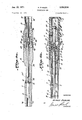
- FIG. 1 is a top plan view of the underwater gun, with a guide pin in the safety position;
- FIG. 2 is a front elevation of FIG. 1;
- FIG. 3 is an enlarged fragmentary top plan view of a portion of FIG. 1, with the handle rotated to the cocked position of the trigger mechanism preparatory to the release thereof for firing;
- FIGS. 4a and 4b are enlarged vertical sectional views of the underwater gun, FIG. 4b being a continuation of the right end of FIG. 4a and showing the trigger mechanism in the cocked position;
- FIG. 5 is an enlarged sectional view along line 5.5 of FIG. 4b;
- FIG. 6 is an enlarged transverse sectional view of the gun head showing the cartridge after the bullet has been fired
- FIG. 7 is a view similar to FIG. 6 illustrating a stage in the movement of the gun casing to effect the discharge of the spent cartridge from the chamber within the barrel;
- FIG. 8 is a view similar to FIG. 7 and illustrating the final stage in the movement of the gun casing and showing the spent cartridge being ejected automatically from the barrel chamber;
- FIG. 9 is a front elevation of the guide bolt in the gun head for the major length thereof.
- FIG. 10 is a fragmentary front perspective view of the head of the guide bolt clearly showing the retaining flange and extractor for the base of the cartridge;
- FIG. 11 is an enlarged sectional view taken along line 11--11 of FIG. 6, clearly showing the four lugs of the gun head in unlocked position;
- FIG. 12 is a view similar to FIG. 11 showing the four lugs of the gun head following their rotation one-eighth of a turn to the locked position;
- FIG. 13 is an enlarged sectional view along line 1313 of FIG. 6;
- FIG. 14 is an enlarged sectional view along line 14-14 of FIG. 6.
- FIGS. 1 and 2 an assembly view of the underwater gun consisting of an elongate breech tube B on one end of which is mounted the handle H, and on the opposite end of which is mounted the gun head.
- the over-all length of the underwater gun may range from four feet to six feet, and it may be carried on a sling if so desired.
- the handle H is formed of an open tubular portion 1 of any desired metal such as aluminum or stainless steel, and preferably is encased on the rearward portion by a plastic handle 2 bearing circumferential ribs on part thereof, as well as grooves 5 defining finger holds to improve the gripping capability of the handle 2 in the course of the manipulation thereof.
- the forward portion 1 of the handle H surrounds the rearward end of the tubular body constituting the breech tube B, which likewise may be formed of aluminum, stainless steel or other non-corroding material, and is provided with a long recess 3 adjacent to a short recess 4 displaced circumferentially from recess 3.
- a pin 6, with an enlarged head 7, serves to fix a bored striker guide sleeve 8 within the breech tube and extends from the latter to serve as a guide pin or limit stop for the movement of the handle 2 when the latter is rotated into the SAFE position, as shown in FIGS. 1 and 2.
- a slight rearward movement of the handle permits the disengagement of the slot 4 from adjacent the enlarged head 7 which, upon being followed by a rotary movement indicated in FIG.
- the trigger mechanism is released near the end of the travel of the handle 2, as explained in detail below.
- This release is effected near the end of this travel of the handle when the pin 7 is closely adjacent the closed end of the slot 3, and the order of this movement may range from one to two inches, so that the firing of the gun must be intentional, following the shifting of the handle from its safety position.
- the release of the trigger mechanism may be executed by contact of the barrel with the underwater animal, or remotely therefrom, by holding the breech tube B while the handle is shifted forwardly from the position shown in FIG. 3 to the point where the base of the slot 3 comes close to the pin 7.
- the breech tube B consists of a tubular portion of approximately four feet in length provided with one or more apertures 10 to relieve the accumulation of water which may collect therein.
- This tube serves as a guide for the striker rod 30 extending centrally thereof from the handle and trigger assembly at the rear end of the gun to the forward portion of the tube wherefrom it extends through the breech extension 38 which is threaded into the forward end of the breech tube.
- the striker rod 30 is guided at the forward end by a bore in the extension 38 and at an intermediate portion of the breech tube by the aforementioned guide sleeve 8, and extends rearwardly therefrom to the trigger assembly constituted in part by a sleeve housing 12 which is threaded at its forward end 13 to the internal threads at the rear end of the breech tube, as clearly shown in FIG. 4b, to constitute a fixed extension of the latter.
- the striker rod 30 is provided with an enlarged abutment 31 for the purpose of seating one end of the propulsion spring 40 for the rod which surrounds an enlarged portion 32 of the striker rod immediately behind the abutment 31, with the other end of the spring 40 seated against a shoulder 17 formed at the end of an enlarged cylindrical cavity of the sleeve housing 12, whereat the striker rod is of lesser diameter than at portion 32.
- This spring 40 is compressed upon pulling back the handle H to cock the gun, and is retained in compressed condition until the gun is fired by a forward movement of the handle to release the locking mechanism for the spring in its compressed position by the assembly described below.
- the metallic tubular handle 1 which is covered on its rearward portion with a hand grip 2 of plastic material, is provided with an internal collar 9 which is fastened to the metallic shell and plastic casing by means of a fastening screw 11.
- the rear threaded end of the striker rod extends through a bore at the rear end of the sleeve onto which is threaded a nut 36 with an intermediate plastic washer 39 of urethane or the like, to operate as a cushioning abutment between the nut 36 and the rear end of the sleeve 9.
- a retaining pin 37 extends transversely through the nut 36 and the rear end of the striker rod to connect these parts securely.
- the striker rod 30 is of different diameters along different lengths of the trigger mechanism and the portion 34 of reduced diameter is disposed between the portion 33 of the striker rod behind portion 32 and the portion 35 of the striker rod which is nested within an enlarged bore of the sleeve 9 and which is surrounded by a coiled spring 43. Both portions 33 and 35 are designed to reciprocate within a central bore of the rearward portion of housing 12 beyond shoulder 17.
- the rear portion of the sleeve housing 12 is provided with a plurality of cylindrical openings 18 for the purpose of seating a plurality of balls 19 which are maintained in yielding engagement with the peripheral surface of the portion 34 of the striker rod.
- These balls which may be four in number, operate as a ball detent for the trigger mechanism and their retention within the recesses 18 of the portion 34 of the striker rod is maintained by a slidable, stepped retainer sleeve 20 which is reciprocable on the rearward lateral wall of the sleeve housing 12, which is of sufficiently reduced diameter to accommodate this portion of the retainer sleeve 20 as well as a coiled spring 41 having one end seated against the rear shoulder 21 of the housing and the opposite end against shoulder 25 of the enlarged rearward portion 24 of the retainer sleeve.
- the spring 41 yieldingly retains the forward portion of the retainer sleeve 20 in overlying relation to the balls 19, which abut against the. junction of the rear end of the enlarged portion of the striker rod with portion 34, to prevent the forward projection of the striker rod despite the compression of spring and the tendency of the striker to be propelled forwardly, to the left as shown in FIG. 4b.
- the ball detent means described above may be releasd by a forward movement of the handle H against the force of spring 43, as shown in FIG. 4b, which initially travels a substantial distance with no effect until the end of the sleeve 9 comes into abutment with the enlarged rear end 24 of the retainer sleeve 20 which encompasses the balls 19.
- the rearward movement of the handle effects a cocking of the gun for a repeated operation, which serves to pull back the sleeve 9 and eventually the terminal washer and nut assembly 37, 36 against the force of spring 40.
- the handle may be fired once again by a forward movement of the handle, as indicated in FIG. 3, or it may be set in the safety position by rotating the handle to seat the pin 7 adjacent the short slot 4, which prevents a forward movement of the handle to release the ball detent locking means for the striker rod.
- the gun head G may assume different structural forms, one preferred embodiment of which is illustrated in FIGS. 6 to 14 and on an enlarged scale in FIG. 4a.
- the gun head G which preferably is detachably connected to the forward end of the breech tube B, comprises essentially a cylindrical guide bolt which is threaded externally at the rear end 59 thereof for threaded engage ment with the forward threaded end of the breech tube extension 38, to render it readily detachable therefrom, as clearly shown in FIG. 4a.
- the bolt is bored centrally with passages of different diameter.
- the forward end 56 is the smallest to accommodate the rounded end of the pin 61, with the main portion of the bore 57' of a larger diameter, and the rear end 58 thereof of still greater diameter, to accommodate the terminal end of the firing pin which consists of an enlarged head portion 62 having a longitudinal slot 63, through which extends a removable pin 64 to confine the movement of the firing pin in a longitudinal direction as controlled by the forward propulsion of the striker rod 30 against the rear end of the firing pin, at which time the latter is forced forwardly through the bolt against the force of spring 67, seated in the cavity 58 between the end of the latter and the enlarged head 62.
- the pin 61 is momentarily projected beyond the end face 51 of the bolt to strike the primer cap of a cartridge C which is adapted to be loaded into the chamber of the gun head for the discharge of the bullet through the barrel thereof.
- the rim of the cartridge is retained against the end of the bolt by means of an extractor 53 disposed in a longitudinal slot 64 in the lateral wall of the bolt with one end thereof retained by a fastener 55 and the opposite end thereof consisting of a nib 57 which is pressed into engagement with the rim of the cartridge and which is free to yield upon automatic discharge of the latter, as shown in FIG. 8.
- the bolt 50 is surrounded by a casing 68 which is movable both reciprocably and rotatably relative to the bolt 50.
- the casing 68 is provided with a plurality of segmental lugs 80 alternating with segmental gaps or spaces 81 which may be four in number, which are complementary to a plurality of segmental lugs 70 on the exterior of the guide bolt 50 adjacent to the rear end thereof, which also alternate with segmental gaps 71 therebetween.
- a guide pin 90 is threaded through the lateral wall of the movable casing and contains, on the interior thereof, a spring-pressed ball 91 which is pressed inwardly by a spring 92 on the interior of the guide pin 90.
- the ball 91 is designed to interengage an L-shaped slot consisting of an elongate portion 85 and a short radial portion 86 extending peripherally on the surface of the bolt 50 (FIG. 9), which serves to enforce a reciprocable movement of the gun casing relative to the central guide bolt until the ball 91 reaches the end of the slot 85 adjacent to the transverse radial portion 86, at which point the casing may execute a slight rotary movement of approximately 45.
- This compulsory movement in a relative longitudinal direction followed by a rotary motion is to dispose the lugs 80 at the inner end of the gun casing into alignment with the segmental gaps 71 adjacent to the end of the guide bolt to permit the execution of the former, which may be followed by the latter rotary motion to dispose the lugs 80 of the casing in alignment with and behind the lugs 71 of the guide bolt, thereby to lock the two parts together against relative longitudinal movement until a preliminary rotary movement is executed in a reverse direction to permit their relative withdrawal in a longitudinal direction.
- FIG. 11 illustrates the positioning of the parts before the casing is rotated relative to the central guide bolt
- FIG. 12 shows these parts after the completion of the rotary movement, which interlocks the casing and guide bolt securely preparatory to the firing of a cartridge and bullet, as shown in FIG. 6.
- more or less than four complementary segmental lugs and gaps may be provided on the bolt and casing to effect the selective coupling therebetween.
- FIGS. 7 and 8 illustrate successive stages in the discharge of the cartridge case after the projection of the bullet in consequence of the firing of the gun which is indicated in FIG. 6.
- the lugs 80 of the casing align with the segmental gaps 71 of the guide bolt, to permit a relative reciprocation of the casing relative to the guide bolt, which is indicated in FIG. 7.
- the end of this travel is shown in FIG. 8 when ball 91 reaches the end of groove 85.
- the peripheral surface of the guide bolt 50 is provided with an L-shaped slot 87, 88 of smaller dimensions than the guide slot 85, 86 the long end of which extends to the end 51 of the guide bolt as well as the annular flange 59 projecting forwardly therefrom, whereat the rim of the cartridge base is seated.
- This guide slot 87, 88 accommodates a pin 95 projecting inwardly from casing 68 into the slot, which pin, at
- the diameter of the bore 77 be reduced relative to the caliber of the bullet A to an extent of 10% to 15% and because of this, it is necessary that the barrel 76 be of limited length and no longer than two and one-half inches. A barrel length of one and threefourths inches has proven very effective.
- the bore diameter may be .303 to .312 inch, so that the propellent force of the cartridge compels a virtual extrusion of the bullet at high force and velocity which the loaded cartridge is capable of accomplishing by virtue of the short length of the barrel. If a bullet of .440 caliber is used, the diameter of the bore should approximate .374 inch.
- the gun head is readily detachable from the breech tube for cleaning and for interchangeability to adapt the gun to different needs.
- the breech tube is provided with openings 10', as is also the end of the handle, to permit the ready evacuation of water from the several parts of the gun.
- My underwater gun operates in the following manner:
- a bullet is loaded into the gun head While the casing 68 is in its forward position, as shown in FIG. 8, and when the rim of the cartridge is seated against the base of the guide-bolt, within annular flange 59, and retained thereagainst by the extractor 53, the casing is reciprocated rearwardly relative to the guide bolt to its limit of movement, at which point it is turned 45 to effect a locking of the cartridge and bullet within the gun head.
- the gun is cocked in preparation for firing by pulling the handle I-I rearwardly relative to the breech tube B which traps the balls 19 of the detent mechanism when the reduced portion 34 of the striker rod arrives adjacent to them to prevent the return movement of the rod despite the compression of spring 40. If it is desired to retain the gun in the SAFE position, the handle is turned to present the safety pin 7 in alignment with the slot 4 at the open end of the handle, which blocks a forward movement of the handle to effect the firing.
- the handle is moved rearwardly to a slight extent in order to clear the end of slot 4 from the pin 7, which is permitted by the elongate reduced portion 34 of the striker rod of the ball detent mechanism, in order to present the safety pin 7 in alignment with the longer slot 3 in the handle 1. In this position the gun is in readiness for firing by moving the handle H forwardly relative to the safety pin 7.
- the portions 33 and 35 of the striker rod are free to move through the retainer sleeve 12 as long as the balls offer no impediment to the travel thereof by being seated in the confined position 34.
- the forward end of the propelled striker rod imparts a sharp blow to the firing pin 61 seated within the guide bolt of the gun head which fires the primer cap of the cartridge, the explosive charge of which forces the bullet A to be extruded through the short barrel 77 of the gun casing with great force and at high velocity.
- the casing After firing, the casing may be given a short turn of 45 to enable the latter to be moved forwardly to discharge automatically the spent cartridge, preparatory to a simple and rapid re-charging of the chamber in the gun head with a new bullet, which is followed by a rearward movement of the gun casing and the locking thereof by a short rotary movement to repeat the cycle of operation described above
- Gun heads with barrels or different sizes may be used interchangeably with a single breech tube and trigger release mechanism.
- An underwater gun comprising:
- said gun head having a chamber therein for a detonating cartridge-case and bullet, with a relatively short cylindrical barrel extending therefrom to the free end of said gun head, said barrel being of reduced diameter relative to the caliber of the bullet whereby the bullet is extruded at high velocity through the short barrel by the propellent explosive charge of the detonated cartridge, and
- said gun head comprises a central guide-bolt having one end thereof connected to said breech tube adjacent to the free end of said striker rod,
- a movable casing comprising said barrel at the free end thereof, reciprocably and rotatably mounted on said guide-bolt and defining, with the free end of said guide-bolt, said chamber for the cartridge-case and bullet,
- said guide-bolt having a central longitudinal bore for said firing pin therein provided with a pointed end at the free end of said guide bolt adjacent to the base of said chamber, and
- said movable handle is rotatably mounted at said end of said breech tube, a stop pin projecting from said tube, and said handle provided with a pair of circumferentially displaced slots of unequal length at the free end thereof for selective alignment with said pin, the short slot adapted to set the trigger mechanism in said locked safety position and the long slot adapted to set the trigger mechanism for release, and operation of said striker rod.
- said trigger mechanism comprises (a) a sleeve housing mounted in the interior of said breech tube, provided with an annular shoulder surrounding said striker rod,
- said restraining means against forward movement comprises ball detent means cooperating with a portion of said striker rod of reduced diameter which is prevented from forward movement by the balls engaging said rod at the reduced section thereof.
Abstract
AN ELONGATE UNDERWATER GUN CAPABLE OF BEING COCKED AND HELD IN THE SAFETY POSITION, OR IN READINESS FIRING BY PUSHING A HANDLE MEMBER ON ONE END OF THE GUN FOR AN APPRECIABLE TRAVEL, OF THE ORDER OF ONE TO TWO INCHES, AT THE END OF WHICH TRAVEL, OF THE ORDER OF ONE TO TWO INCHES, DETONATE A PRIMER CAP OF A CARTRIDGE TO PROPEL A BULLET THROUGH A BARREL OF SHORT LENGTH AT THE OPPOSITE END OF THE GUN, WHICH IS DISCHARGED THEREFROM AT HIGH PRESSURE AND VELOCITY. THE GUN IS CAPABLE OF BEING RE-LOADED QUICKLY AND RELIABLY WHILE SUBMERGED UNDER WATER TO REPEAT THE FIRING OPERATION AFTER COCKING THE GUN FOR SETTING IN THE SAFETY OR FIRING POSITION.
Description
Jan. 12, 1971 v A. ENGLER ,8
7 I UNDERWATER GUN Filed Feb} 20. 1969 3 Sheets-Sheet 1 N (9 INVENTOR &
ATTORNEY A. ENGLER 3,553,876
UNDERWATER GUN 3 Sheets-Sheet 2 INVENTOR ATT RNEY Jan. 12,1911
Filed Feb. 20, 1969 Patented Jan. 12, 1971 3,553,876 UNDERWATER GUN Alfred Engler, 1020 NE. 196th Terrace, North Miami Beach, Fla. 33162 Filed Feb. 20, 1969, Ser. No. 801,002 Int. Cl. F41c 3/00, 7/00 US. Cl. 42-1 14 Claims ABSTRACT OF THE DISCLOSURE An elongate underwater gun capable of being cocked and held in the safety position, or in readiness for firing by pushing a handle member on one end of the gun for an appreciable travel, of the order of one to two inches, at the end of which travel, a firing pin is propelled to detonate a primer cap of a cartridge to propel a bullet through a barrel of short length at the opposite end of the gun, which is discharged therefrom at high pressure and velocity. The gun is capable of being re-loaded quickly and reliably while submerged under water to repeat the firing operation after cocking the gun for setting in the safety or firing position.
This invention relates to an underwater gun which may be used in the field of water sports and particularly to a gun which may be used as a defense gun against sharks, as well as a hunting gun for fish, under or above water from boats. It may also be used as a flare gun in circumstances of distress, as well as a defense gun above water.
It is the object of the present invention to provide an underwater gun which has a good feel and which may be handled both safely and effectively to discharge high velocity projectiles under water with a capability of reloading the gun quickly with a cartridge case and bullet which may be fired under high pressure and velocity by contact with the target or remotely therefrom.
It is a further object of the invention to provide an elongate underwater gun of from four feet to six feet in length, having a convenient and easily grasped handle on one end, which may be easily shifted from safety to firing position, and which may be actuated for firing in the latter position by the release of a trigger mechanism associated with a striker rod within a breech tube which acts to propel a firing pin at the opposite end of the gun. The firing pin constitutes part of a detachable gun head having a barrel of comparatively short length through which the bullet is driven under tremendous pressure and force by the percussion of the firing pin against the primer cap of the cartridge containing the bullet and the explosive charge. The bullet is virtually extruded at high velocity through the barrel in consequence of the reduced diameter of the barrel relative to the caliber of the bullet. A simple manipulation of the gun head quickly effects the automatic discharge of the spent cartridge from the chamber therein, which may be re-loaded quickly with a new cartridge and bullet and locked into position for a subsequent firing by another simple manipulation of the gun head. The striker rod may be cocked for the next firing, either before or after re-loading, by a return movement of the handle, which may be set in either a safety or firing position for the next operation.
It is another object of the invention to advance the art of underwater fishing by providing a gun having many distinct advantages over those employed heretofore such as spear guns and even those of the type using projectiles as disclosed in US. Pat. No. 3,300,888, Jan. 31, 1967.
Other objects and purposes will appear from the detailed description of the invention following hereinafter, taken in conjunction with the accompanying drawings, wherein:
FIG. 1 is a top plan view of the underwater gun, with a guide pin in the safety position;
FIG. 2 is a front elevation of FIG. 1;
FIG. 3 is an enlarged fragmentary top plan view of a portion of FIG. 1, with the handle rotated to the cocked position of the trigger mechanism preparatory to the release thereof for firing;
FIGS. 4a and 4b are enlarged vertical sectional views of the underwater gun, FIG. 4b being a continuation of the right end of FIG. 4a and showing the trigger mechanism in the cocked position;
FIG. 5 is an enlarged sectional view along line 5.5 of FIG. 4b;
FIG. 6 is an enlarged transverse sectional view of the gun head showing the cartridge after the bullet has been fired;
FIG. 7 is a view similar to FIG. 6 illustrating a stage in the movement of the gun casing to effect the discharge of the spent cartridge from the chamber within the barrel;
FIG. 8 is a view similar to FIG. 7 and illustrating the final stage in the movement of the gun casing and showing the spent cartridge being ejected automatically from the barrel chamber;
FIG. 9 is a front elevation of the guide bolt in the gun head for the major length thereof;
FIG. 10 is a fragmentary front perspective view of the head of the guide bolt clearly showing the retaining flange and extractor for the base of the cartridge;
FIG. 11 is an enlarged sectional view taken along line 11--11 of FIG. 6, clearly showing the four lugs of the gun head in unlocked position;
FIG. 12 is a view similar to FIG. 11 showing the four lugs of the gun head following their rotation one-eighth of a turn to the locked position;
FIG. 13 is an enlarged sectional view along line 1313 of FIG. 6; and
FIG. 14 is an enlarged sectional view along line 14-14 of FIG. 6.
In FIGS. 1 and 2 is shown an assembly view of the underwater gun consisting of an elongate breech tube B on one end of which is mounted the handle H, and on the opposite end of which is mounted the gun head. The over-all length of the underwater gun may range from four feet to six feet, and it may be carried on a sling if so desired.
The handle H is formed of an open tubular portion 1 of any desired metal such as aluminum or stainless steel, and preferably is encased on the rearward portion by a plastic handle 2 bearing circumferential ribs on part thereof, as well as grooves 5 defining finger holds to improve the gripping capability of the handle 2 in the course of the manipulation thereof.
The forward portion 1 of the handle H surrounds the rearward end of the tubular body constituting the breech tube B, which likewise may be formed of aluminum, stainless steel or other non-corroding material, and is provided with a long recess 3 adjacent to a short recess 4 displaced circumferentially from recess 3. A pin 6, with an enlarged head 7, serves to fix a bored striker guide sleeve 8 within the breech tube and extends from the latter to serve as a guide pin or limit stop for the movement of the handle 2 when the latter is rotated into the SAFE position, as shown in FIGS. 1 and 2. A slight rearward movement of the handle permits the disengagement of the slot 4 from adjacent the enlarged head 7 which, upon being followed by a rotary movement indicated in FIG. 3 by arrow R, places the long slot 3 in alignment with the stop pin 7, so that upon forward movement of the handle in the direction indicated by arrow A, the trigger mechanism is released near the end of the travel of the handle 2, as explained in detail below. This release is effected near the end of this travel of the handle when the pin 7 is closely adjacent the closed end of the slot 3, and the order of this movement may range from one to two inches, so that the firing of the gun must be intentional, following the shifting of the handle from its safety position. Furthermore, the release of the trigger mechanism may be executed by contact of the barrel with the underwater animal, or remotely therefrom, by holding the breech tube B while the handle is shifted forwardly from the position shown in FIG. 3 to the point where the base of the slot 3 comes close to the pin 7.
The breech tube B consists of a tubular portion of approximately four feet in length provided with one or more apertures 10 to relieve the accumulation of water which may collect therein. This tube serves as a guide for the striker rod 30 extending centrally thereof from the handle and trigger assembly at the rear end of the gun to the forward portion of the tube wherefrom it extends through the breech extension 38 which is threaded into the forward end of the breech tube. The striker rod 30 is guided at the forward end by a bore in the extension 38 and at an intermediate portion of the breech tube by the aforementioned guide sleeve 8, and extends rearwardly therefrom to the trigger assembly constituted in part by a sleeve housing 12 which is threaded at its forward end 13 to the internal threads at the rear end of the breech tube, as clearly shown in FIG. 4b, to constitute a fixed extension of the latter.
The striker rod 30 is provided with an enlarged abutment 31 for the purpose of seating one end of the propulsion spring 40 for the rod which surrounds an enlarged portion 32 of the striker rod immediately behind the abutment 31, with the other end of the spring 40 seated against a shoulder 17 formed at the end of an enlarged cylindrical cavity of the sleeve housing 12, whereat the striker rod is of lesser diameter than at portion 32. This spring 40 is compressed upon pulling back the handle H to cock the gun, and is retained in compressed condition until the gun is fired by a forward movement of the handle to release the locking mechanism for the spring in its compressed position by the assembly described below.
The metallic tubular handle 1, which is covered on its rearward portion with a hand grip 2 of plastic material, is provided with an internal collar 9 which is fastened to the metallic shell and plastic casing by means of a fastening screw 11. The rear threaded end of the striker rod extends through a bore at the rear end of the sleeve onto which is threaded a nut 36 with an intermediate plastic washer 39 of urethane or the like, to operate as a cushioning abutment between the nut 36 and the rear end of the sleeve 9. A retaining pin 37 extends transversely through the nut 36 and the rear end of the striker rod to connect these parts securely.
The striker rod 30 is of different diameters along different lengths of the trigger mechanism and the portion 34 of reduced diameter is disposed between the portion 33 of the striker rod behind portion 32 and the portion 35 of the striker rod which is nested within an enlarged bore of the sleeve 9 and which is surrounded by a coiled spring 43. Both portions 33 and 35 are designed to reciprocate within a central bore of the rearward portion of housing 12 beyond shoulder 17.
The rear portion of the sleeve housing 12 is provided with a plurality of cylindrical openings 18 for the purpose of seating a plurality of balls 19 which are maintained in yielding engagement with the peripheral surface of the portion 34 of the striker rod. These balls, which may be four in number, operate as a ball detent for the trigger mechanism and their retention within the recesses 18 of the portion 34 of the striker rod is maintained by a slidable, stepped retainer sleeve 20 which is reciprocable on the rearward lateral wall of the sleeve housing 12, which is of sufficiently reduced diameter to accommodate this portion of the retainer sleeve 20 as well as a coiled spring 41 having one end seated against the rear shoulder 21 of the housing and the opposite end against shoulder 25 of the enlarged rearward portion 24 of the retainer sleeve. The spring 41 yieldingly retains the forward portion of the retainer sleeve 20 in overlying relation to the balls 19, which abut against the. junction of the rear end of the enlarged portion of the striker rod with portion 34, to prevent the forward projection of the striker rod despite the compression of spring and the tendency of the striker to be propelled forwardly, to the left as shown in FIG. 4b.
The ball detent means described above may be releasd by a forward movement of the handle H against the force of spring 43, as shown in FIG. 4b, which initially travels a substantial distance with no effect until the end of the sleeve 9 comes into abutment with the enlarged rear end 24 of the retainer sleeve 20 which encompasses the balls 19. The continued movement of the handle and sleeve 9 against the force of spring 43, which normally forces the base of the sleeve against the cushioning washer 39 at the end of the striking rod, eventually effects a reciprocating movement of the retainer sleeve 20 against the force of spring 41, and when the enlarged portion 24 comes into overlying relation with the recesses 18 and the balls 19 retained therein, the force of spring 40, which tends to move the striker rod 30 to the left, as shown in FIG. 4b, results in the camming out of the balls by the filleted terminal portion 34a so that they now become seated between the enlarged portion 35 and the internal wall of the enlarged end 24 of retainer sleeve 20, to free the striker rod 30 for a strong propulsion to the left until the washer 39 adjacent the end of the striker rod comes into abutment with the rear end of the sleeve 9. This motion is sufiicient to forcefully propel forward the end of the striker rod against the tail end of the firing pin of the gun head, which is described in greater detail below.
The rearward movement of the handle effects a cocking of the gun for a repeated operation, which serves to pull back the sleeve 9 and eventually the terminal washer and nut assembly 37, 36 against the force of spring 40. The withdrawal of the enlarged portion 35 of the striker rod from adjacent the enlarged portion 24 of the retainer sleeve 20, permits balls 19 to be reseated adjacent to the reduced portion 34 of the striker rod, which is aided by the rearward movement of the retainer sleeve 20 in consequence of the expansion of spring 41. Once the gun is cocked and the trigger mechanism locked against movement by the ball detent means, the handle may be fired once again by a forward movement of the handle, as indicated in FIG. 3, or it may be set in the safety position by rotating the handle to seat the pin 7 adjacent the short slot 4, which prevents a forward movement of the handle to release the ball detent locking means for the striker rod.
The gun head G may assume different structural forms, one preferred embodiment of which is illustrated in FIGS. 6 to 14 and on an enlarged scale in FIG. 4a.
The gun head G, which preferably is detachably connected to the forward end of the breech tube B, comprises essentially a cylindrical guide bolt which is threaded externally at the rear end 59 thereof for threaded engage ment with the forward threaded end of the breech tube extension 38, to render it readily detachable therefrom, as clearly shown in FIG. 4a. The bolt is bored centrally with passages of different diameter. The forward end 56 is the smallest to accommodate the rounded end of the pin 61, with the main portion of the bore 57' of a larger diameter, and the rear end 58 thereof of still greater diameter, to accommodate the terminal end of the firing pin which consists of an enlarged head portion 62 having a longitudinal slot 63, through which extends a removable pin 64 to confine the movement of the firing pin in a longitudinal direction as controlled by the forward propulsion of the striker rod 30 against the rear end of the firing pin, at which time the latter is forced forwardly through the bolt against the force of spring 67, seated in the cavity 58 between the end of the latter and the enlarged head 62.
The pin 61 is momentarily projected beyond the end face 51 of the bolt to strike the primer cap of a cartridge C which is adapted to be loaded into the chamber of the gun head for the discharge of the bullet through the barrel thereof.
The rim of the cartridge is retained against the end of the bolt by means of an extractor 53 disposed in a longitudinal slot 64 in the lateral wall of the bolt with one end thereof retained by a fastener 55 and the opposite end thereof consisting of a nib 57 which is pressed into engagement with the rim of the cartridge and which is free to yield upon automatic discharge of the latter, as shown in FIG. 8.
The bolt 50 is surrounded by a casing 68 which is movable both reciprocably and rotatably relative to the bolt 50. The casing 68 is provided with a plurality of segmental lugs 80 alternating with segmental gaps or spaces 81 which may be four in number, which are complementary to a plurality of segmental lugs 70 on the exterior of the guide bolt 50 adjacent to the rear end thereof, which also alternate with segmental gaps 71 therebetween.
A guide pin 90 is threaded through the lateral wall of the movable casing and contains, on the interior thereof, a spring-pressed ball 91 which is pressed inwardly by a spring 92 on the interior of the guide pin 90. The ball 91 is designed to interengage an L-shaped slot consisting of an elongate portion 85 and a short radial portion 86 extending peripherally on the surface of the bolt 50 (FIG. 9), which serves to enforce a reciprocable movement of the gun casing relative to the central guide bolt until the ball 91 reaches the end of the slot 85 adjacent to the transverse radial portion 86, at which point the casing may execute a slight rotary movement of approximately 45. The purpose of this compulsory movement in a relative longitudinal direction followed by a rotary motion, is to dispose the lugs 80 at the inner end of the gun casing into alignment with the segmental gaps 71 adjacent to the end of the guide bolt to permit the execution of the former, which may be followed by the latter rotary motion to dispose the lugs 80 of the casing in alignment with and behind the lugs 71 of the guide bolt, thereby to lock the two parts together against relative longitudinal movement until a preliminary rotary movement is executed in a reverse direction to permit their relative withdrawal in a longitudinal direction.
FIG. 11 illustrates the positioning of the parts before the casing is rotated relative to the central guide bolt, while FIG. 12 shows these parts after the completion of the rotary movement, which interlocks the casing and guide bolt securely preparatory to the firing of a cartridge and bullet, as shown in FIG. 6.
If desired, more or less than four complementary segmental lugs and gaps may be provided on the bolt and casing to effect the selective coupling therebetween.
The gun head is provided with a short barrel 76 at its forward end in advance of the cartridge chamber, and a lateral opening 78 beyond the latter permits the cartridge to be loaded and discharged. FIGS. 7 and 8 illustrate successive stages in the discharge of the cartridge case after the projection of the bullet in consequence of the firing of the gun which is indicated in FIG. 6. Upon the rotation of the casing 68 relative to the guide bolt, as permitted by groove portion 86, the lugs 80 of the casing align with the segmental gaps 71 of the guide bolt, to permit a relative reciprocation of the casing relative to the guide bolt, which is indicated in FIG. 7. The end of this travel is shown in FIG. 8 when ball 91 reaches the end of groove 85. In order to effect an automatic discharge of the spent cartridge case, the peripheral surface of the guide bolt 50 is provided with an L-shaped slot 87, 88 of smaller dimensions than the guide slot 85, 86 the long end of which extends to the end 51 of the guide bolt as well as the annular flange 59 projecting forwardly therefrom, whereat the rim of the cartridge base is seated. This guide slot 87, 88 accommodates a pin 95 projecting inwardly from casing 68 into the slot, which pin, at
the end of the withdrawal movement of the casing, strikes at the base of the cartridge rim to dislodge it from the end of the guide bolt and its retention by the spring nib 57 to eifect the discharge thereof, as indicated in FIG. 8. This discharge of the empty cartridge case may be followed by the insertion of a new cartridge and bullet which is seated on the end of the guide bolt, and which may be retained in the chamber of the gun head upon the return reciprocation of the casing relative to the guide bolt, which is permitted by the movements of both the pin in guide slot 87 and the guiding ball 91 in guide slot 85, followed by a rotary movement of the casing relative to the guide bolt by virtue of the peripheral portions 88 and 86 of the guide slots.
It is essential that the diameter of the bore 77 be reduced relative to the caliber of the bullet A to an extent of 10% to 15% and because of this, it is necessary that the barrel 76 be of limited length and no longer than two and one-half inches. A barrel length of one and threefourths inches has proven very effective. Thus, when the bullet caliber is .357, the bore diameter may be .303 to .312 inch, so that the propellent force of the cartridge compels a virtual extrusion of the bullet at high force and velocity which the loaded cartridge is capable of accomplishing by virtue of the short length of the barrel. If a bullet of .440 caliber is used, the diameter of the bore should approximate .374 inch.
As described above, the gun head is readily detachable from the breech tube for cleaning and for interchangeability to adapt the gun to different needs. The breech tube is provided with openings 10', as is also the end of the handle, to permit the ready evacuation of water from the several parts of the gun.
My underwater gun operates in the following manner:
A bullet is loaded into the gun head While the casing 68 is in its forward position, as shown in FIG. 8, and when the rim of the cartridge is seated against the base of the guide-bolt, within annular flange 59, and retained thereagainst by the extractor 53, the casing is reciprocated rearwardly relative to the guide bolt to its limit of movement, at which point it is turned 45 to effect a locking of the cartridge and bullet within the gun head.
The gun is cocked in preparation for firing by pulling the handle I-I rearwardly relative to the breech tube B which traps the balls 19 of the detent mechanism when the reduced portion 34 of the striker rod arrives adjacent to them to prevent the return movement of the rod despite the compression of spring 40. If it is desired to retain the gun in the SAFE position, the handle is turned to present the safety pin 7 in alignment with the slot 4 at the open end of the handle, which blocks a forward movement of the handle to effect the firing.
Whenever the gun is ready for firing, the handle is moved rearwardly to a slight extent in order to clear the end of slot 4 from the pin 7, which is permitted by the elongate reduced portion 34 of the striker rod of the ball detent mechanism, in order to present the safety pin 7 in alignment with the longer slot 3 in the handle 1. In this position the gun is in readiness for firing by moving the handle H forwardly relative to the safety pin 7. The movement results in a forward travel of the sleeve 9 within the handle against the compression spring 43 until the forward end of the sleeve abuts against the rear end of collar 20, which now moves together with the sleeve 9 against the additional resistance of coil spring 41 until the enlarged end 24 of the sleeve comes into the field of operation of the balls 19 which are retained within the Openings 18 of the sleeve housing 12. As soon as the balls are capable of being released from the confining portion 34 by outward travel into the enlarged interior 24 of collar 20, the striker rod 30 is free to be propelled forwardly by the main spring 40 which was compressed upon cocking between the shoulder 31 on the striker rod and the internal shoulder 17 within the sleeve housing 12. The portions 33 and 35 of the striker rod are free to move through the retainer sleeve 12 as long as the balls offer no impediment to the travel thereof by being seated in the confined position 34. The forward end of the propelled striker rod imparts a sharp blow to the firing pin 61 seated within the guide bolt of the gun head which fires the primer cap of the cartridge, the explosive charge of which forces the bullet A to be extruded through the short barrel 77 of the gun casing with great force and at high velocity. After firing, the casing may be given a short turn of 45 to enable the latter to be moved forwardly to discharge automatically the spent cartridge, preparatory to a simple and rapid re-charging of the chamber in the gun head with a new bullet, which is followed by a rearward movement of the gun casing and the locking thereof by a short rotary movement to repeat the cycle of operation described above Gun heads with barrels or different sizes may be used interchangeably with a single breech tube and trigger release mechanism.
While I have described my invention as embodied in a specific form and as operating in a specific manner for purposes of illustration, it should be understood that I do not limit my invention thereto, since various modifications will suggest themselves to those skilled in the art without departing from the spirit of my invention, the scope of which is set forth in the annexed claims.
I claim:
1. An underwater gun comprising:
(a) an elongate breech tube having a gun head mounted at one end thereof and a trigger mechanism at the opposite end thereof,
(b) a movable handle mounted on said last-mentioned end of said breech tube connected to said trigger mechanism for alternatively setting said mechanism into the locked safety position and in position for actuating said trigger mechanism by a forward movement of said handle,
(c) a striker rod extending through said breech tube from said trigger mechanism to said gun head,
(d) said gun head having a chamber therein for a detonating cartridge-case and bullet, with a relatively short cylindrical barrel extending therefrom to the free end of said gun head, said barrel being of reduced diameter relative to the caliber of the bullet whereby the bullet is extruded at high velocity through the short barrel by the propellent explosive charge of the detonated cartridge, and
(e) a firing pin in said gun head extending between the base of said chamber and the free end of said striker rod adapted to be actuated by the release of said trigger mechanism.
2. A device as set forth in claim 1, wherein the length of the barrel ranges from one to two inches, and the diameter thereof is from to 15% less than the caliber of the bullet.
3. A device as set forth in claim 1, wherein said gun head comprises a central guide-bolt having one end thereof connected to said breech tube adjacent to the free end of said striker rod,
(a) a movable casing, comprising said barrel at the free end thereof, reciprocably and rotatably mounted on said guide-bolt and defining, with the free end of said guide-bolt, said chamber for the cartridge-case and bullet,
(b) said guide-bolt having a central longitudinal bore for said firing pin therein provided with a pointed end at the free end of said guide bolt adjacent to the base of said chamber, and
(c) the opposite end of said firing pin having spring means and a longitudinal slot with a restraining pin therein for resiliently withdrawing said firing pin from said chamber while permitting momentary projection thereinto by the forward movement of said striker rod.
4. A device as set forth in claim 3, including a plurality fit of segmental lugs with intervening spaces on the interior of said movable casing at the end thereof remote from said barrel, adapted to cooperate with a plurality of alternating segmental lugs with intervening spaces on the exterior of said guid bolt adjacent to the breech tube, and said guide bolt having an L-shaped groove extending longitudinally of the external surface thereof adapted to cooperate with a projection on said casing extending in wardly into said groove for permitting the execution of a fixed relative reciprocating movement between the guide bolt and casing followed by a limited rotary movement therebetween which locks the segmental lugs in alignment behind each other and a consequent sealing of the chamber containing the cartridge-case and bullet.
5. A device as set forth in claim 4, wherein said movable casing is provided with an opening in the lateral wall thereof which is adapted to overlie the free end of the guide-bolt in the sealed position of the chamber and which, in the relatively extended position of the movable casing, is adapted to provide a passage for the insertion of a detonating cartridge-case and bullet into said chamber adjacent to the free end of said guide-bolt.
6. A device as set forth in claim 5, including an extractor afiixed to the lateral wall of said guide-bolt having a lateral projection at the free end thereof for engaging the rim at the base of the cartridge-case.
7. A device as set forth in claim 6, wherein said guide bolt is provided with an auxiliary L-shaped slot in the external wall thereof, and a pin on said movable casing opposite said lateral opening and projecting into said slot to permit said casing to execute, without hindrance, the alternating rotary and reciprocating movements relative to said guide bolt, and adapted to strike the rim of the cartridge-case at the conclusion of the outward movement of the movable casing to eject the spent cartridge from the chamber.
8. A device as set forth in claim 1, wherein said movable handle is rotatably mounted at said end of said breech tube, a stop pin projecting from said tube, and said handle provided with a pair of circumferentially displaced slots of unequal length at the free end thereof for selective alignment with said pin, the short slot adapted to set the trigger mechanism in said locked safety position and the long slot adapted to set the trigger mechanism for release, and operation of said striker rod.
9. A device as set forth in claim 8, wherein said trigger mechanism comprises (a) a sleeve housing mounted in the interior of said breech tube, provided with an annular shoulder surrounding said striker rod,
(b) a propulsion spring for said striker rod having one end thereof seated adjacent said shoulder,
(c) an annular abutment on said striker rod displaced forwardly from said shoulder for seating the opposite end of said spring,
(d) means for compressing said spring by a rearward movement of said handle,
(e) means for restraining forward movement of said last-mentioned abutment, and
(f) means for inactivating said last-mentioned means in response to the forward movement of said handle along the longer slot relative to said stop pin.
10. A device as set forth in claim 9, wherein said restraining means against forward movement comprises ball detent means cooperating with a portion of said striker rod of reduced diameter which is prevented from forward movement by the balls engaging said rod at the reduced section thereof.
11. A device as set forth in claim 10, including (a) a reciprocable collar surrounding said sleeve housing at the rearward edge thereof for confining said balls to the portion of the rod of reduced section,
(b) said collar being of enlarged diameter at the rear ward end thereof, and
(c) a coil spring surrounding said collar adapted to bias said collar in a rearward direction.
12. A device as set forth in claim 11, including an abutment on the interior of said handle adapted to engage the rearward end of said collar at the end of said forward movement of said handle to dispose the enlarged diameter of said collar at said balls to effect the release of the ball detent means from the portion of said striker rod of reduced diameter, and thereby to permit the forward propulsion of said striker rod.
13. A device as set forth in claim 10, wherein said striker rod of reduced section is of sutficient length to permit a slight rearward movement thereof while blocking a forward movement following the cocking of the trigger mechanism.
14. A device as set forth in claim 1, wherein said gun UNITED STATES PATENTS 3,118,242 1/1964 Snyder 42-11, 3,210,877 10/1965 Liberatore 42--1L 3,300,888 1/1967 Belcher et al 421L BENJAMIN A. BORCHELT, Primary Examiner C. T. JORDAN, Assistant Examiner
Applications Claiming Priority (1)
| Application Number | Priority Date | Filing Date | Title |
|---|---|---|---|
| US80100269A | 1969-02-20 | 1969-02-20 |
Publications (1)
| Publication Number | Publication Date |
|---|---|
| US3553876A true US3553876A (en) | 1971-01-12 |
Family
ID=25179936
Family Applications (1)
| Application Number | Title | Priority Date | Filing Date |
|---|---|---|---|
| US801002A Expired - Lifetime US3553876A (en) | 1969-02-20 | 1969-02-20 | Underwater gun |
Country Status (1)
| Country | Link |
|---|---|
| US (1) | US3553876A (en) |
Cited By (7)
| Publication number | Priority date | Publication date | Assignee | Title |
|---|---|---|---|---|
| US3653139A (en) * | 1970-11-03 | 1972-04-04 | Mine Safety Appliances Co | Firing mechanism for explosively actuated tool |
| US4100692A (en) * | 1977-08-02 | 1978-07-18 | Cameron Larry D | Underwater protection device |
| US4644930A (en) * | 1984-07-18 | 1987-02-24 | Robert Mainhardt | Gun for firing a variety of projectiles |
| US4757628A (en) * | 1987-03-27 | 1988-07-19 | Bulfer Gary M | Shark saber |
| WO2007131781A1 (en) * | 2006-05-17 | 2007-11-22 | Heckler & Koch Gmbh | Weapon locking system |
| US20110017796A1 (en) * | 2008-02-27 | 2011-01-27 | Powers Products Iii, Llc | Setting tool arrangement |
| US10520278B2 (en) | 2017-06-29 | 2019-12-31 | Spike's Tactical, Llc | Auto-loading underwater firearm |
-
1969
- 1969-02-20 US US801002A patent/US3553876A/en not_active Expired - Lifetime
Cited By (11)
| Publication number | Priority date | Publication date | Assignee | Title |
|---|---|---|---|---|
| US3653139A (en) * | 1970-11-03 | 1972-04-04 | Mine Safety Appliances Co | Firing mechanism for explosively actuated tool |
| US4100692A (en) * | 1977-08-02 | 1978-07-18 | Cameron Larry D | Underwater protection device |
| US4644930A (en) * | 1984-07-18 | 1987-02-24 | Robert Mainhardt | Gun for firing a variety of projectiles |
| US4757628A (en) * | 1987-03-27 | 1988-07-19 | Bulfer Gary M | Shark saber |
| WO2007131781A1 (en) * | 2006-05-17 | 2007-11-22 | Heckler & Koch Gmbh | Weapon locking system |
| US20100282064A1 (en) * | 2006-05-17 | 2010-11-11 | Wolfgang Bantle | Locking systems for use with firearms |
| US8074556B2 (en) | 2006-05-17 | 2011-12-13 | Heckler & Koch, Gmbh | Locking systems for use with firearms |
| KR101097502B1 (en) | 2006-05-17 | 2011-12-22 | 헤클러 운트 코흐 게엠베하 | Weapon locking system |
| US20110017796A1 (en) * | 2008-02-27 | 2011-01-27 | Powers Products Iii, Llc | Setting tool arrangement |
| US8397968B2 (en) * | 2008-02-27 | 2013-03-19 | Black & Decker Inc. | Setting tool arrangement |
| US10520278B2 (en) | 2017-06-29 | 2019-12-31 | Spike's Tactical, Llc | Auto-loading underwater firearm |
Similar Documents
| Publication | Publication Date | Title |
|---|---|---|
| US3736839A (en) | Dual mode shotgun | |
| US3306168A (en) | Gas operated semi-automatic pistol | |
| US3236155A (en) | Firearm having an auxiliary bolt closure mechanism | |
| US3237335A (en) | Safety firearm and ammunition for the same | |
| US4579037A (en) | Machine pistol with retarded blowback | |
| US3208176A (en) | Safety device for guns | |
| US4028994A (en) | Micro-precision timed firing handgun | |
| US3142293A (en) | Method of launching a projectile using compressed gas | |
| US3009453A (en) | Toy | |
| US9103623B2 (en) | Cartridge gas energized gun for arrows, darts and the like | |
| US4625442A (en) | Cattle stunning gun | |
| US3168744A (en) | Explosively-actuated stud-driving tool | |
| US3553876A (en) | Underwater gun | |
| US3908626A (en) | Air gun mechanism arrangement | |
| US3514026A (en) | Repeating propellant gas powered driving tool | |
| US3274936A (en) | Explosive spearhead | |
| US3580172A (en) | Underwater projectile for firing a cartridge upon impact | |
| US3145494A (en) | Muzzle-triggered gun | |
| US3270455A (en) | Semi-automatic repeating flare pistol | |
| US4867040A (en) | Self-unlocking device for recoiling bolt carrier and barrel in a semi-automatic rifle | |
| US3616561A (en) | Multiple bore gun having a rotatable barrel | |
| US3210877A (en) | Underwater weapon | |
| US3302840A (en) | Explosively actuated fastener driving tool | |
| US3217441A (en) | Practice firearm | |
| US3139692A (en) | Cartridge powered spear gun |