US3542965A - Inter-office call diverter - Google Patents
Inter-office call diverter Download PDFInfo
- Publication number
- US3542965A US3542965A US737979A US3542965DA US3542965A US 3542965 A US3542965 A US 3542965A US 737979 A US737979 A US 737979A US 3542965D A US3542965D A US 3542965DA US 3542965 A US3542965 A US 3542965A
- Authority
- US
- United States
- Prior art keywords
- station
- transfer
- circuit
- call
- marker
- Prior art date
- Legal status (The legal status is an assumption and is not a legal conclusion. Google has not performed a legal analysis and makes no representation as to the accuracy of the status listed.)
- Expired - Lifetime
Links
- 238000012546 transfer Methods 0.000 description 100
- 239000003550 marker Substances 0.000 description 62
- 230000005540 biological transmission Effects 0.000 description 18
- 238000004891 communication Methods 0.000 description 9
- 230000006870 function Effects 0.000 description 8
- 238000004804 winding Methods 0.000 description 5
- 238000000034 method Methods 0.000 description 3
- 238000004080 punching Methods 0.000 description 3
- 230000004044 response Effects 0.000 description 3
- 230000009471 action Effects 0.000 description 2
- 239000004020 conductor Substances 0.000 description 2
- 230000006872 improvement Effects 0.000 description 2
- 230000004913 activation Effects 0.000 description 1
- 238000010276 construction Methods 0.000 description 1
- 230000001419 dependent effect Effects 0.000 description 1
- 238000011161 development Methods 0.000 description 1
- 238000010586 diagram Methods 0.000 description 1
- 230000002401 inhibitory effect Effects 0.000 description 1
- 238000003780 insertion Methods 0.000 description 1
- 230000037431 insertion Effects 0.000 description 1
- 238000007689 inspection Methods 0.000 description 1
- 238000009434 installation Methods 0.000 description 1
- 238000012423 maintenance Methods 0.000 description 1
- 230000005055 memory storage Effects 0.000 description 1
- 230000000704 physical effect Effects 0.000 description 1
- 230000008569 process Effects 0.000 description 1
- 238000012545 processing Methods 0.000 description 1
- 230000009897 systematic effect Effects 0.000 description 1
- 238000012360 testing method Methods 0.000 description 1
- 238000013519 translation Methods 0.000 description 1
- 230000001755 vocal effect Effects 0.000 description 1
Images


Classifications
-
- H—ELECTRICITY
- H04—ELECTRIC COMMUNICATION TECHNIQUE
- H04Q—SELECTING
- H04Q3/00—Selecting arrangements
- H04Q3/42—Circuit arrangements for indirect selecting controlled by common circuits, e.g. register controller, marker
- H04Q3/54—Circuit arrangements for indirect selecting controlled by common circuits, e.g. register controller, marker in which the logic circuitry controlling the exchange is centralised
- H04Q3/545—Circuit arrangements for indirect selecting controlled by common circuits, e.g. register controller, marker in which the logic circuitry controlling the exchange is centralised using a stored programme
-
- Y—GENERAL TAGGING OF NEW TECHNOLOGICAL DEVELOPMENTS; GENERAL TAGGING OF CROSS-SECTIONAL TECHNOLOGIES SPANNING OVER SEVERAL SECTIONS OF THE IPC; TECHNICAL SUBJECTS COVERED BY FORMER USPC CROSS-REFERENCE ART COLLECTIONS [XRACs] AND DIGESTS
- Y10—TECHNICAL SUBJECTS COVERED BY FORMER USPC
- Y10S—TECHNICAL SUBJECTS COVERED BY FORMER USPC CROSS-REFERENCE ART COLLECTIONS [XRACs] AND DIGESTS
- Y10S379/00—Telephonic communications
- Y10S379/914—Programmable telephone component
Definitions
- the Voice communication path from the calling station is always extended to the transfer station through auxiliary equipment associated with the called line.
- auxiliary equipment associated with the called line.
- I. Wicks U.S. Pat. 2,274,759 dated Mar. 3, 1942 teaches a transfer system wherein the auxiliary circuits for bridging the incoming call to the transfer station are permanently associated with the called subscribers telephone.
- An improvement over this arrangement is disclosed in the W. Whitney U.S. Pat. 3,377,433 dated Apr. 9, 1968 which teaches a transfer system wherein the auxiliary voice bridging circuits are associated with the called line only while a call is being processed involving the called line.
- a register which is attached to the established connection at the calling oice in response to the signal, causes the C appearance of the switching circuit in the called office to initiate a connection to a sender.
- the sender in the called oiiice thereupon transmits to the register in the calling oce, the directory digits of the transfer station.
- the original connection between the calling ofce and the called office then releases and a new connection is established to the transfer station under control of the calling ofce in the same manner as though the call had originated in the calling office. Communication is thereby possible from the calling station to the transfer station through the normal switching system without the insertion of auxiliary transfer circuits or switching offices into the nal voice connection. Thus, proper transmission quality is maintained on the transfer connection at all times.
- a temporary call transfer switching system is arranged to accomplish the actual transfer at a switching ofce serving a calling station.
- a called office of a multiple oiiice switching system is arranged to recognize the special status of a called line and to initiate a connection from a calling oice to a preselected transfer station independent from an originally established connection from the calling oice to the called oice.
- a switching system at the called oce is arranged to recognize the special status of a called line and to divert calls incoming to that line to an auxiliary transfer circuit and to thereupon transmit to the calling office the digits of a transfer number to which calls are to be transferred.
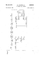
- FIGS. 2 through 14 are schematic drawings showing in greater detail the interrelation of the components of the exemplary embodiment.
- FIGS. 2 through 14 employ a type of notation referred to as detached contact in which an X shown intersecting a conductor represents a normally open contact of a relay and a bar shown intersecting a conductor at right angles represents a normally closed contact of a relay; normally referring to the unoperated condition of the relay.
- the principles of this type of notation are described in an article entitled An Improved Detached Contact Type Schematic Circuit Drawing by F. T. Meyer in the September 1955 publication of the American Institute of the Electrical Engineers Transactions, Communications and Electronics, vol. 74, pages 505-513.
- the relays, relay contacts and other electromechanical devices shown in FIGS. 2 through 14 have been given systematic designations.
- the number preceding the letters of each device correspond to the iigure in which the control circuit of the de vice is shown.
- the coil of relay 5T is shown in FIG. 5.
- Each relay contact, either make, break or transfer, is shown with its specific contact number preceded by the designation of the relay to which it belongs.
- the notation 5T-1 indicates contact number 1 of relay 5T, the coil of which is shown in FIG. 5.
- memory circuit 7 may constitute any one of a number of configurations well known in the art operable to electrically record information in binary form at preselected address locations, each of which address location is effective to provide the information stored therein on a nondestructive read-out basis.
- marker circuit ⁇ 8 is arranged, as described in the aforementioned Busch patent, to connect line link frame 2 appearance R with trunk link frame 3 appearance X in the normal manner such that digits transmitted from station S2 will be received in originating register circuit 6.
- marker circuit 8 then causes the registration of the class of service and the calling line equipment location of station S2 in the originating register. The marker thereupon releases from the connection.
- incoming trunk circuit ⁇ 4 is activated by an incoming call which is directed to station S2.
- number group circuit 11 is interrogated to determine the line equipment information and ringing combination of the called party.
- the marker is arranged to recognize the privileged status of the called station fro-m its preassigned ringing combination.
- the preassignment of a specified ringing combination may be utilized, as herein set forth.
- numerous other techniques may be employed. For example, an additional translation indication may be returned by the number group in the manner set forth in T. V. Burns et al., U.S. Pat. 3,264,415, dated Aug. 2, 1966.
- ringing tone is applied to the line.
- the switching circuit is arranged to immediately detect this ringing potential and to trip the ringing.
- the switching circuit thereupon initiates a signal over the extended linkage path to the calling oice A.
- This signal is detected in the calling oflice by the outgoing trunk 101 which is arranged, via an auxiliary line link frame appearance Z to initiate a dial tone connection and thus have an originating register attached in the normal manner. Attachment of the originating register causes the auxiliary switching circuit in the called ofiice, in the manner to -be more fully detailed hereinafter, to become attached through the switching network to a sender for the transmission of the digital directory number of the transfer station S3.
- the called office may be aranged to select, from a class of service code assigned to the incoming trunk, whether the calling office is equipped for automatic call transfer.
- the incoming connection may have been switched through numerous switching offices it would be necessary to modify each of these offices in order to insure that the proper trunk is selected for the final connection to the called oce.
- station S2 is arranged for temporary call transfer service.
- the corresponding class of service designation is class of service 29. It will thus be obvious, as set forth in the Busch patent, that during the establishment of an originating or terminating connection involving station S2, marker circuit 8 will ascertain the class of service of station S2 to be that designated 29 and therefore will function in accordance with that class of service in processing such connections.
- station S2 desires to have incoming calls transferred to some other telephone location such as station S3 as hereinbefore set forth.
- relays 7CAO, 7CA1, 7CBO and 7CB1 (FIG. 7) operate over an obvious path from the corresponding leads of the register relays, FIG. 3, via cable 57.
- These relays thereupon lock operate in an obvious manner and provide an operate path for the TIT relay from battery through the winding of the relay, released break contact 7CB2-1, enabled make contacts 7CB1-1, 7CBO-3, 7CA1-1 and 7CAO-1, to ground which, as has been set forth previously, is present on output lead A of class of service translator circuit 707.
Landscapes
- Engineering & Computer Science (AREA)
- Computer Networks & Wireless Communication (AREA)
- Sub-Exchange Stations And Push- Button Telephones (AREA)
- Exchange Systems With Centralized Control (AREA)
Applications Claiming Priority (1)
| Application Number | Priority Date | Filing Date | Title |
|---|---|---|---|
| US73797968A | 1968-06-18 | 1968-06-18 |
Publications (1)
| Publication Number | Publication Date |
|---|---|
| US3542965A true US3542965A (en) | 1970-11-24 |
Family
ID=24966064
Family Applications (1)
| Application Number | Title | Priority Date | Filing Date |
|---|---|---|---|
| US737979A Expired - Lifetime US3542965A (en) | 1968-06-18 | 1968-06-18 | Inter-office call diverter |
Country Status (7)
| Country | Link |
|---|---|
| US (1) | US3542965A (de) |
| JP (1) | JPS4617361B1 (de) |
| BE (1) | BE734674A (de) |
| DE (1) | DE1930309C3 (de) |
| FR (1) | FR2011154A1 (de) |
| GB (1) | GB1271548A (de) |
| SE (1) | SE376526B (de) |
Cited By (2)
| Publication number | Priority date | Publication date | Assignee | Title |
|---|---|---|---|---|
| US4555594A (en) * | 1983-08-03 | 1985-11-26 | At&T Bell Laboratories | Telephone interexchange signaling protocol |
| US5903642A (en) * | 1997-09-24 | 1999-05-11 | Call-A-Guide, Inc. | Method for eliminating telephone hold time |
Families Citing this family (7)
| Publication number | Priority date | Publication date | Assignee | Title |
|---|---|---|---|---|
| BE541276A (de) * | 1954-09-14 | |||
| DE3027147C2 (de) * | 1980-07-17 | 1982-09-30 | Siemens AG, 1000 Berlin und 8000 München | Schaltungsanordnung für Fernmeldevermittlungsanlagen, insbesondere Fernsprechvermittlungsanlagen, mit über Verbindungswege übertragenen Gebührenzählinformationen |
| DE3027113C2 (de) * | 1980-07-17 | 1984-05-17 | Siemens AG, 1000 Berlin und 8000 München | Schaltungsanordnung für Fernmeldevermittlungsanlagen, insbesondere Fernsprechvermittlungsanlagen mit vorübergehend nicht erreichbaren Teilnehmerstellen |
| DE3027141C2 (de) * | 1980-07-17 | 1982-10-07 | Siemens AG, 1000 Berlin und 8000 München | Schaltungsanordnung für Fernmeldevermittlungsanlagen, insbesondere Fernsprechvermittlungsanlagen, mit über Verbindungswege übertragenen Gebührenzählinformationen |
| DE3027129C2 (de) * | 1980-07-17 | 1982-10-07 | Siemens AG, 1000 Berlin und 8000 München | Schaltungsanordnung für Fernmeldevermittlungsanlagen, insbesondere Fernsprechvermittlungsanlagen, mit über Verbindungswege übertragenen Gebührenzählinformationen |
| DE3027176C2 (de) * | 1980-07-17 | 1982-09-02 | Siemens AG, 1000 Berlin und 8000 München | Schaltungsanordnung für Fernmeldevermittlungsanlagen, insbesondere Fernsprechvermittlungsanlagen, in denen gebührenpflichtige sowie gebührenfreie Verbindungen hergestellt werden |
| JPS6331342A (ja) * | 1986-07-25 | 1988-02-10 | Hashimoto Corp | 遠隔操作可能な電話転送先変更装置 |
Citations (1)
| Publication number | Priority date | Publication date | Assignee | Title |
|---|---|---|---|---|
| GB1126209A (en) * | 1965-04-28 | 1968-09-05 | Int Standard Electric Corp | Improvements in or relating to telecommunication systems |
-
1968
- 1968-06-18 US US737979A patent/US3542965A/en not_active Expired - Lifetime
-
1969
- 1969-06-10 SE SE6908222A patent/SE376526B/xx unknown
- 1969-06-14 DE DE1930309A patent/DE1930309C3/de not_active Expired
- 1969-06-17 FR FR6920201A patent/FR2011154A1/fr not_active Withdrawn
- 1969-06-17 BE BE734674D patent/BE734674A/xx not_active IP Right Cessation
- 1969-06-17 GB GB30512/69A patent/GB1271548A/en not_active Expired
- 1969-06-18 JP JP4769269A patent/JPS4617361B1/ja active Pending
Patent Citations (1)
| Publication number | Priority date | Publication date | Assignee | Title |
|---|---|---|---|---|
| GB1126209A (en) * | 1965-04-28 | 1968-09-05 | Int Standard Electric Corp | Improvements in or relating to telecommunication systems |
Cited By (3)
| Publication number | Priority date | Publication date | Assignee | Title |
|---|---|---|---|---|
| US4555594A (en) * | 1983-08-03 | 1985-11-26 | At&T Bell Laboratories | Telephone interexchange signaling protocol |
| US5903642A (en) * | 1997-09-24 | 1999-05-11 | Call-A-Guide, Inc. | Method for eliminating telephone hold time |
| US6049603A (en) * | 1997-09-24 | 2000-04-11 | Call-A-Guide, Inc. | Method for eliminating telephone hold time |
Also Published As
| Publication number | Publication date |
|---|---|
| DE1930309B2 (de) | 1974-01-10 |
| FR2011154A1 (de) | 1970-02-27 |
| JPS4617361B1 (de) | 1971-05-14 |
| BE734674A (de) | 1969-12-01 |
| GB1271548A (en) | 1972-04-19 |
| SE376526B (de) | 1975-05-26 |
| DE1930309C3 (de) | 1974-08-01 |
| DE1930309A1 (de) | 1970-02-12 |
Similar Documents
| Publication | Publication Date | Title |
|---|---|---|
| US3854013A (en) | Call forwarding arrangement | |
| US3854014A (en) | Call back arrangement | |
| US3555196A (en) | Telephone switching system with programmed auxiliary control for providing special services | |
| US3573389A (en) | Switching system with individual register control | |
| US3542965A (en) | Inter-office call diverter | |
| US3736383A (en) | Multicustomer centralized call diverter | |
| US5063592A (en) | Control of non-locally switched telecommunication services | |
| US4232198A (en) | Device for establishing conference calls via at least one telephone exchange switching system | |
| US3542961A (en) | Call forwarding equipment for operators | |
| US3544729A (en) | Switching system arrangement for terminating a call to a line other than a called line | |
| US3515812A (en) | Call forwarding system | |
| US3062918A (en) | Automatic call recording system | |
| US3479467A (en) | Pbx in-dialing | |
| US3462557A (en) | Intra-concentrator call detecting circuit | |
| US3544728A (en) | Pbx telephone system wherein switch units served through different central offices are controlled by control unit at one central office | |
| US3705275A (en) | Telephone trunk testing system | |
| US2998493A (en) | Office translator arrangement for switching systems | |
| US3350509A (en) | Time division tone signaling system | |
| US3377433A (en) | Switching system arrangement for providing multiple switching network line appearances without preassignment | |
| US3420958A (en) | Communication system with alternate data link | |
| US2913526A (en) | Calling station identification circuit | |
| US3458662A (en) | Crossbar switching with special service provisions | |
| US3412211A (en) | Call tracing method and arrangement | |
| JPS58187057A (ja) | 短縮ダイヤル呼出方式 | |
| US3143601A (en) | Automatic number intercept identification system |