US3524461A - Fluid logic element - Google Patents
Fluid logic element Download PDFInfo
- Publication number
- US3524461A US3524461A US3524461DA US3524461A US 3524461 A US3524461 A US 3524461A US 3524461D A US3524461D A US 3524461DA US 3524461 A US3524461 A US 3524461A
- Authority
- US
- United States
- Prior art keywords
- passage
- stream
- logic element
- pressure
- chamber
- Prior art date
- Legal status (The legal status is an assumption and is not a legal conclusion. Google has not performed a legal analysis and makes no representation as to the accuracy of the status listed.)
- Expired - Lifetime
Links
- 239000012530 fluid Substances 0.000 title description 44
- 238000011144 upstream manufacturing Methods 0.000 description 6
- 230000000694 effects Effects 0.000 description 5
- 230000001154 acute effect Effects 0.000 description 1
- 230000000903 blocking effect Effects 0.000 description 1
- 238000006243 chemical reaction Methods 0.000 description 1
- 238000010276 construction Methods 0.000 description 1
- 230000007423 decrease Effects 0.000 description 1
- 230000005764 inhibitory process Effects 0.000 description 1
- 238000009434 installation Methods 0.000 description 1
- 239000007788 liquid Substances 0.000 description 1
- 239000000463 material Substances 0.000 description 1
- 239000002184 metal Substances 0.000 description 1
- 229920003023 plastic Polymers 0.000 description 1
- 239000004033 plastic Substances 0.000 description 1
- 230000000750 progressive effect Effects 0.000 description 1
- 238000011084 recovery Methods 0.000 description 1
- 239000007787 solid Substances 0.000 description 1
- 238000006467 substitution reaction Methods 0.000 description 1
Images


Classifications
-
- F—MECHANICAL ENGINEERING; LIGHTING; HEATING; WEAPONS; BLASTING
- F15—FLUID-PRESSURE ACTUATORS; HYDRAULICS OR PNEUMATICS IN GENERAL
- F15C—FLUID-CIRCUIT ELEMENTS PREDOMINANTLY USED FOR COMPUTING OR CONTROL PURPOSES
- F15C1/00—Circuit elements having no moving parts
- F15C1/08—Boundary-layer devices, e.g. wall-attachment amplifiers coanda effect
- F15C1/10—Boundary-layer devices, e.g. wall-attachment amplifiers coanda effect for digital operation, e.g. to form a logical flip-flop, OR-gate, NOR-gate, AND-gate; Comparators; Pulse generators
-
- F—MECHANICAL ENGINEERING; LIGHTING; HEATING; WEAPONS; BLASTING
- F15—FLUID-PRESSURE ACTUATORS; HYDRAULICS OR PNEUMATICS IN GENERAL
- F15C—FLUID-CIRCUIT ELEMENTS PREDOMINANTLY USED FOR COMPUTING OR CONTROL PURPOSES
- F15C1/00—Circuit elements having no moving parts
- F15C1/08—Boundary-layer devices, e.g. wall-attachment amplifiers coanda effect
-
- Y—GENERAL TAGGING OF NEW TECHNOLOGICAL DEVELOPMENTS; GENERAL TAGGING OF CROSS-SECTIONAL TECHNOLOGIES SPANNING OVER SEVERAL SECTIONS OF THE IPC; TECHNICAL SUBJECTS COVERED BY FORMER USPC CROSS-REFERENCE ART COLLECTIONS [XRACs] AND DIGESTS
- Y10—TECHNICAL SUBJECTS COVERED BY FORMER USPC
- Y10T—TECHNICAL SUBJECTS COVERED BY FORMER US CLASSIFICATION
- Y10T137/00—Fluid handling
- Y10T137/206—Flow affected by fluid contact, energy field or coanda effect [e.g., pure fluid device or system]
- Y10T137/2229—Device including passages having V over T configuration
- Y10T137/2234—And feedback passage[s] or path[s]
-
- Y—GENERAL TAGGING OF NEW TECHNOLOGICAL DEVELOPMENTS; GENERAL TAGGING OF CROSS-SECTIONAL TECHNOLOGIES SPANNING OVER SEVERAL SECTIONS OF THE IPC; TECHNICAL SUBJECTS COVERED BY FORMER USPC CROSS-REFERENCE ART COLLECTIONS [XRACs] AND DIGESTS
- Y10—TECHNICAL SUBJECTS COVERED BY FORMER USPC
- Y10T—TECHNICAL SUBJECTS COVERED BY FORMER US CLASSIFICATION
- Y10T137/00—Fluid handling
- Y10T137/206—Flow affected by fluid contact, energy field or coanda effect [e.g., pure fluid device or system]
- Y10T137/2229—Device including passages having V over T configuration
- Y10T137/224—With particular characteristics of control input
-
- Y—GENERAL TAGGING OF NEW TECHNOLOGICAL DEVELOPMENTS; GENERAL TAGGING OF CROSS-SECTIONAL TECHNOLOGIES SPANNING OVER SEVERAL SECTIONS OF THE IPC; TECHNICAL SUBJECTS COVERED BY FORMER USPC CROSS-REFERENCE ART COLLECTIONS [XRACs] AND DIGESTS
- Y10—TECHNICAL SUBJECTS COVERED BY FORMER USPC
- Y10T—TECHNICAL SUBJECTS COVERED BY FORMER US CLASSIFICATION
- Y10T137/00—Fluid handling
- Y10T137/206—Flow affected by fluid contact, energy field or coanda effect [e.g., pure fluid device or system]
- Y10T137/2229—Device including passages having V over T configuration
- Y10T137/2256—And enlarged interaction chamber
Definitions
- This invention comprehends a fluid logic element operated by pressure fluids and serving to direct a fluid stream in various directions in dependence upon appropriate actuation, the fluid logic element comprising a nozzle of a fluid trigger extending into a reflection chamber for delivering a fluid stream into said chamber so that said stream divides said chamber into two compartments, means defining an exit orifice from said chamber, of substantially the same cross-section as said stream, between two convergent walls of said chamber, and means to produce pressure differences as between the two compartments so as to deflect said stream, said exit orifice being followed by divergent walls for guiding the deflected stream towards appropriate exit passages.
- FLUID LOGIC ELEMENT This invention relates to a fluid logic element operated by pressure fluids in liquid or gas form, e.g. compressed air, and serving to direct a fluid stream in various directions in dependence upon appropriate actuation.
- the nozzle of a fluid trigger extends into a reflection chamber for delivering a fluid stream into said chamber so that said stream divides said chamber into two compartments, said chamber being formed with an exit orifice, of substantially the same cross-section as the stream, between two convergent walls of the chamber, means being provided to produce pressure differences as between the two compartments so as to deflect the stream, the exit orifice being followed by divergent walls for guiding the deflected stream towards appropriate exit passages.
- the logic element or at least its chamber is symmetrical of the nozzle centre plane, stable operation in both the directions of the exit stream is obtained and the element is a bistable. If sufficient asymmetry is introduced, the stream tends to be deflected in a privileged or preferred direction and the element is a monostable.
- the element operates by the fluid stream being reflected on one of the convergent walls of the chamber, the exit stream being guided along the opposite divergent wall towards the corresponding exit passage.
- lf inter alia deflection is produced by a pressure fluid entering one of the reflection chamber compartments, the fact that the stream exits at the side where the actuation occurs means that, if required, an active negative feedback of the exit on the actuation can be provided and that the logic elements of a system disposed in a single plane can be interconnected without the passages crossing one another.
- the reflection chamber exit orifice dimensions are such relatively to the cross-section of the stream and therefore to the noule exit cross-section that the pressure tends to increase in the reflection chamber. Consequently, the element can be actuated without the need for any actuating fluid delivery, and so a single element can actuate a large number of other elements.
- the element can operate as an ordinary trigger and provide various functions such as and," or, nor etc.
- the logic elements provided by the invention are very stable and can hold the load, and can therefore be used to control elements, such as distributors or manocontactors which of course operate with a zero continuous rate of flow.
- FIGURE 1 is a view, in section on the line H of FIGURE 2, of a bistable logic element according to the invention
- FIGURE 2 is a view in section on the line "-11 of FIGURE 1;
- FIGURE 3 is a view, in section onthe line Ill-Ill of FIGURE 4, of a monostable logic element
- FIGURE 4 is a section on the line lV-lV of FIGURE 3;
- FIGURES 5 and 6 are pairs of views, similar to the pairs formed by the preceding figures, but relating to a logic element for performing the and" function;
- FIGURES 7 and 8 are a pair of views, similar to FIGURES 5 and 6 but of a logic element for performing the or-nor" function;
- FIGURES 9 and 10 form another similar pair of views but relating to an alternative construction of the exit passages and leakage ducts of the element;
- FIGURE 11 is a sectioned view of an aerodynamic valve facility
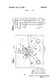
- FIGURE 12 is a diagrammatic view in longitudinal section of an asymmetrical trigger to show the effects of the reflecting-wall angles on trigger operation;
- FIGURE 13 is a view similar to FIGURE 12 showing a logic element with negative feedback derived from the exit passages;
- FIGURE 14 is a view similar to FIGURE 13 except that the negative feedback is derived from the passages communicating with atmosphere;
- FIGURE 15 is a view in longitudinal section of an isolating circuit
- FIGURE 16 is a view in longitudinal section of a bistable logic element having a preferred orientation
- FIGURE 17 is a view similar to FIGURE 16 and shows a logic element in which each control passage is combined with an isolating circuit, and
- FIGURE 18 is a view similar to FIGURES l6 and 17 and shows a logic element having double-input isolating circuits.
- a logic element comprises three plates or sheets of some appropriate material e.g. plastics or metal or the like which is compatible with the fluids used; the three sheets are assembled in hermetic face-to-face relationship.
- the rear sheet 1 is solid, the central sheet 2 is perforated to form the chambers and ducting to be described hereinafter, and the front plate 3 is pierced with apertures for the connection of supply tubing 4, exit tubing 5 and actuating tubing 6.
- the central sheet 2 is formed opposite the supply tubing or duct 4 with a cavity 7 which terminates in a relatively narrow rectangular passage, preferablyihaving parallel surfaces, and which forms an input or entry nozzle 8 of the logic element.
- the nozzle 8 is adapted to deliver a stream 9, the same entering a reflection chamber 10 which is of constant thickness and which is in cross-section shaped substantially like an isosceles or, preferably, equilateral triangle.
- the stream 9 enters the chamber 10 perpendicularly to one of the sides of the triangular cross-section.
- Control passages 11a, 11b extend from the vertices at each end of such side to the actuating tubes 6.
- exit or output orifice 12 whose width is of the same order as the width of the orifice of the input nozzle 8.
- exit or output passages 13a, 13b Connected to the output orifice 12 are exit or output passages 13a, 13b bounded at their origin by side walls 14a, 14b, which can be curvilinear or plane, and by a pointed central apex 15.
- the passages 13a, 13b diverge at a reduced angle, e.g. of from about 7 to 11, so that the stream is recompressed as a result of the progressive increase in flow cross-section presented to it.
- the passages 13a, 13b extend to the exit passages 5 through which the fluid goes to appropriate loads.
- Leakage ducts 16a, 16b are connected laterally to the exit passages 13a, 13b; the ducts 16a, 16b extend to a medium at a lower pressure than the pressure of the stream e.g. atmosphere if a stream of compressed gas such as air is inputto the logic element.
- the ducts 16a, 16b join the passages 13a, 13b at an inclination directed upstream, then extend as a wide elbow and then diverge towards the end walls of the central sheet or plate 2.
- the output orifice 12 is disposed opposite the nozzle 8 and the logic element reflection chamber 10 is symmetrical of the nozzle centre plane.
- the stream 9 delivered by the nozzle 8 divides the chamber 10 into two lateral compartments 10a, 10b. If the width of the output orifice 12 is at least equal to stream width, the stream can pass readily through the orifice l2 and the pressure set up in the compartments 10a, 10b tends to be less than the pressure in the control passages 6; for instance, if the control passages 6 are connected to atmosphere, the pressure in the compartments 10a, 10b will tend to be less than atmospheric pressure.
- the main stream is urged towards chamber wall 17b and, reflected thereby, departs via the channel 13a along the wall 14a.
- the actuating stream applied via the channel 11a is cut off and an actuating fluid stream is applied via the passage 1 lb.
- the main stream leaves through that passage which is disposed on the same side as the actuating or control passage via which the actuating stream of fluid is applied.
- the width of the output orifice 12 is less than main stream width, the operation differs slightly from what has just been described in that the pressure in the chamber tends to be greater in proportion as the orifice 12 is narrower.
- the main stream widens as the fluid moves away from the nozzle orifice, the same effect can be obtained if the output orifice 12 has the same width as the exit cross-section of the nozzle 8.
- the device has a slight tendency to be biased towards operation in one particular direction at start-up. If perfect symmetry could be achieved and if the pressure in the two control passages 11a, 11b was the same, there would be no reason for the main stream to deflect to either hand. Since perfect symmetry is unattainable in practice, the main stream is always deflected slightly in the conditions assumed.
- the device can be actuated by either of the actuating passages 6 being supplied with an appropriate pressure fluid; in practice, however, since fluid always tends to escape via the control passages, actuation can be produced just by blocking the control passage on the side to which deflection is required. For instance, in the start-up case just described, where the stream is deflected first to the right and then to the exit passage 13a, if the escape of fluid through the passage 11b is inhibited, the pressure in the compartment 10b gradually rises and the stream deflects towards the wall 17a, with the result that the logic element reverses or flip-flops", the main stream then departing through the exit passage 13b.
- fluid can escape through the ducts 16a, 16b if the rate of flow in the passages 13a or 13b decreases for any reason.
- the position and shape of the ducts 16a, 16b depends upon pressure requirements in the element.
- the angle at which the ducts 16a, 161) are connected to the output passages 13a, 13b is such that the ducts 16a, 16b can, by aspirator action, help to increase the output rate of flow through the load tubes.
- the logic elements can operate in both directions with comparable conditions of stability and can be considered to be a bistable, but the element shown in FIGURES 3 and 4 differs slightly in that it is asymmetrical, the nozzle 8 not being disposed exactly opposite the output orifice 12 of the chamber 10. Consequently, if the pressure in the control passages 11a, 11b is assumed to be the same, the main stream strikes the edge of the wall 17a and is therefore deflected towards the output passage 13b.
- the element is monostable since special actuation i.e., sufficient excess pressure in the compartment 10a is required to deflect the main stream into the output passage 13a.
- the element Upon the cessation of actuation the element changes over automatically, the main stream returning to the passage 13b, which is called the preferred passage.
- the passage 13b which is called the preferred passage.
- asymmetry in the other direction would make the channel 13a the preferred channel.
- the monostable element operates exactly like the bistable element.
- FIGURES 5 and 6 show one possible use of a monostable element as an active and" circuit.
- the nozzle 8 is offset to the left from the output orifice 12. It is assumed that the device is supplied, e.g. with compressed air, via the tubing,
- the actuating passage 11b and the ducts 16a, 16b are connected to atmosphere.
- the actuating passage 11a branches into a number, e. g. two, of channels which extend to relatively large-diameter tubes 20, 21.
- the ratio of the nozzle exit orifice to the chamber output orifice 12 is such that a slight positive pressure tends to be produced in the chamber 10. If the passages 6, 20, 21 are connected to atmosphere the stream 9 goes through the preferred passage 13b. lf e.g.
- the facility shown in FllGUlRE l 1 comprises an injector 31 which can be supplied e.g. with pressure fluid from an output of a previous logic element; the facility also comprises a large cross-section diffuser 33 connected to one of the tubes or ducts 20 or 21, the other of which also has a facility similar to the facility shown in FIGURE 1 1. Operation is as follows:
- the injector When supplied with pressure fluid the injector produces a positive pressure in the diffuser 33 and therefore in one of the ducts 20 or 21; when the injector is not so supplied, the diffuser 33 is at ambient pressure. If just one of the injectors associated with the ducts 20, 21 is energised, the control pressure in the compartment 10a remains very near ambient pressure since delivery is via the other control and does not cause flip-flopping.
- the element is again of the monostable kind, with a tendency for the pressure to increase in the chamber 10.
- the control passage 11a is connected by passages 22-25 to a number e.g. four of fluid diodes 26-29 which, of course take the form of a cylindrical capacity comprising a tangential nozzle and a central nozzle.
- the pressure loss is much greater for fluid movements from the tangential towards the central nozzle than vice versa.
- the four passages 22-25 are connected to the tangential nozzles of the corresponding fluid diodes 26-29, the central nozzles thereof being connected to control passages 30. If none of the central nozzles is closed, the logic element delivers to the preferred or privileged passage 13b.
- the nozzles are so calibrated that energisation of any single one of them leads to a sufficient pressure increase in chamber compartment 10a for the main stream to change over from passage 13b to passage 13a.
- the flow through the passage 13b therefore corresponds to the NOR" function and the flow through the passage 13a corresponds to the OR function.
- FIGURES 9 and i0 is similar to the embodiment shown in FIGURES l and 2 except that the output passages 13a, 13b are straight and the leakage ducts 16a, 16b are disposed immediately after the chamber output orifice l2 and extend to tubes or passages 31.
- bistable or monostable logic elements can be devised on the basis of appropriately determining the angles a (1 formed by the convergent reflecting walls 17a, 17b of the chamber 10 with a perpendicular to the direction of the main stream leaving the nozzle 8.
- a is usually from 50 to 80", preferably 60, in which event the preferred value of ar for a monostable trigger is 40.
- the trigger shown in in FIGURE 12, for which these values are used, is monostable and the passage 13a is the preferred output passage.
- each of the output orifices 5a, 5b to which the output passages 13a, 13b extend is connected to the corresponding control passage 11a, 11b by a respective negative feedback duct or passage 34a, 34b which are disposed at an obtuse angle after the passages 13a, 13b to ensure sufficient recovery of dynamic pressure for negative feedback to occur even when the output is not loaded. If the output is gradually loaded, the negative feedback increases, with increasing inhibition of the main stream.
- the output can be fully loaded and, indeed, the output pressure can be artificially increased (by an auxiliary supply) beyond the maximum pressure of which the device is capable, but no accidental flip-flopping occurs.
- This overload feature may beinvaluable in cases in which the logic element is used to control a closed-capacity device, such as a manocontactor, disposed some distance away; if the supply pressure varies, a temporary overload on the line can exist.
- the negative feedback passages 34a, 34b can, with advantage, be connected to the passages 16a, 16b, communicating with atmosphere, and this feature is shown in FIGURE 14.
- the amount of negative feedback is small when the output impedance is small, but increases progressively in proportion as the load increases, since the delivery to atmosphere increases. Consequently, this feature can be used for all load values only in the case of bistables (symmetrical elements); with monostables the load on the normally unsupplied channel must be high enough.
- the negative feedback passages extend directly to the chamber 10, a feature which helps to save space.
- FIGURE 15 diagrammatically shows an isolating circuit comprising a receiver capacity 35 connected by a direct passage 36 to orifice 37 communicating with atmosphere. Extending into passage 36 is a passage 38 connected to a tube 39 via which a signal may arrive. Duct or passage 38 makes an appreciable angle with passage 36; opposite the place where passage 38 meets passage 36 is a concavity 40.
- the isolating circuit can be considered to be a fluid diode; a pressure pulse transmitted through the tube 39 reaches the capacity 35 directly, whereas fluid transmitted into the capacity 35 goes through the passage 36 towards the orifice 37 without any delivery or appreciable pressure variation occurring in the duct 38.
- a circuit of this kind associated with the control channel helps to decouple the fluid circuits from one another.
- FIGURES 16-18 show examples of logic elements in which an association of the kind just mentioned is used.
- a negative feedback produces a pressure rise in the element reflection chamber 10.
- the pressure rise might reach the control passages and disturb the circuits connected thereto, for instance in cases in which the same signal controls two logic elements.
- the use of an isolating circuit protects the control channels from the effects of such positive pressure and also ensures that excessive actuating pressure does not act via the trigger on the opposite control channel (a phenomenon known as transparency" of the trigger).
- the element has an asymmetrical reflection chamber 10, the output passage 13b being privileged or preferred.
- the corresponding control passage 11b is combined with an isolating circuit whose chamber 10 forms the receiving capacity; the direct passage 41 communicates with atmosphere and the signal arrival duct 42 is connected to the control passage or orifice 6b of the logic element.
- the other control passage Ila is similarly connected to the output orifice 5a via a direct passage 43, which serves as negative feedback passage for the normally unstable passage 13a and to the actuating passage or orifice 6a via a branch duct 44.
- the resulting element is a bistable element having a preferred orientation. At start-up and in the absence of control, delivery is via the normally supplied passage 13b. Consequently, there is no ambiguity at start-up. Upon cessation of the control, whichever passage was supplied continues to be supplied until the next change of control.
- the element shown in FIGURE 17 is symmetrical and, as in the case shown in FIGURE 14, has negative feedback ducts 34a, 34b which connect to the chamber 10 the passages 16a, 16b communicating with atmosphere.
- Each control passage 11a, 11b is combined with an isolating circuit whose direct passage 41a, 41b communicates with atmosphere, a branched passage or duct 42a, 42b being connected to the control passage or orifice 6a, 6b. This feature is advantageous inter alia if the control signal is small ,on reduced load.
- the device shown in FIGURE 18 has negative feedbacks connected to the output orifices in the manner described with reference to FIGURE 13.
- Each control passage 11a, 11b is combined with an isolating circuit having two input ducts; the direct passage 41a or 41b communicates with atmosphere and the input ducts take the form of one of the negative feedback ducts 34a or 34b and the other of a branched duct connected to the input orifice (sic) 6a or.6b of the logic element. This feature precludes pressure rises in the control passages.
- a fluid logic element comprising:
- a reflection chamber 10 provided with an inlet nozzle (8) to deliver a fluid stream (9) into said chamber, said fluid stream defining two separate compartments in said chamber;
- said chamber being bounded by:
- said inlet nozzle being arranged in said upstream, transverse wall in laterally spaced relationship with respect to the upstream ends of said downstream converging side walls;
- each said isolating circuit comprises a second branch duct in the form of a negative feedback duct connected to the trigger exit.
Landscapes
- Engineering & Computer Science (AREA)
- General Engineering & Computer Science (AREA)
- Theoretical Computer Science (AREA)
- Physics & Mathematics (AREA)
- Fluid Mechanics (AREA)
- Mechanical Engineering (AREA)
- Jet Pumps And Other Pumps (AREA)
- Infusion, Injection, And Reservoir Apparatuses (AREA)
- Physical Or Chemical Processes And Apparatus (AREA)
- Nozzles (AREA)
Applications Claiming Priority (2)
| Application Number | Priority Date | Filing Date | Title |
|---|---|---|---|
| FR103679A FR1530484A (fr) | 1967-04-21 | 1967-04-21 | élément logique à fluide |
| FR141616A FR94386E (fr) | 1967-04-21 | 1968-02-28 | Élément logique a fluide. |
Publications (1)
| Publication Number | Publication Date |
|---|---|
| US3524461A true US3524461A (en) | 1970-08-18 |
Family
ID=26175820
Family Applications (1)
| Application Number | Title | Priority Date | Filing Date |
|---|---|---|---|
| US3524461D Expired - Lifetime US3524461A (en) | 1967-04-21 | 1968-04-11 | Fluid logic element |
Country Status (5)
| Country | Link |
|---|---|
| US (1) | US3524461A (en:Method) |
| BE (1) | BE713555A (en:Method) |
| DE (1) | DE1750284C3 (en:Method) |
| FR (2) | FR1530484A (en:Method) |
| GB (1) | GB1219003A (en:Method) |
Cited By (4)
| Publication number | Priority date | Publication date | Assignee | Title |
|---|---|---|---|---|
| DE2819656A1 (de) * | 1977-05-07 | 1978-11-09 | Matsushita Electric Ind Co Ltd | Ablenkvorrichtung fuer stroemendes medium |
| US4148333A (en) * | 1975-11-08 | 1979-04-10 | Matsushita Electric Industrial Co., Ltd. | Fluid diverting assembly |
| US4205597A (en) * | 1975-11-08 | 1980-06-03 | Matsushita Electric Industrial Co., Ltd. | Air conditioner having fluid air diverting assembly |
| US4630689A (en) * | 1985-03-04 | 1986-12-23 | Hughes Tool Company-Usa | Downhole pressure fluctuating tool |
-
1967
- 1967-04-21 FR FR103679A patent/FR1530484A/fr not_active Expired
-
1968
- 1968-02-28 FR FR141616A patent/FR94386E/fr not_active Expired
- 1968-04-10 GB GB1724468A patent/GB1219003A/en not_active Expired
- 1968-04-11 US US3524461D patent/US3524461A/en not_active Expired - Lifetime
- 1968-04-11 BE BE713555D patent/BE713555A/xx unknown
- 1968-04-18 DE DE1750284A patent/DE1750284C3/de not_active Expired
Cited By (4)
| Publication number | Priority date | Publication date | Assignee | Title |
|---|---|---|---|---|
| US4148333A (en) * | 1975-11-08 | 1979-04-10 | Matsushita Electric Industrial Co., Ltd. | Fluid diverting assembly |
| US4205597A (en) * | 1975-11-08 | 1980-06-03 | Matsushita Electric Industrial Co., Ltd. | Air conditioner having fluid air diverting assembly |
| DE2819656A1 (de) * | 1977-05-07 | 1978-11-09 | Matsushita Electric Ind Co Ltd | Ablenkvorrichtung fuer stroemendes medium |
| US4630689A (en) * | 1985-03-04 | 1986-12-23 | Hughes Tool Company-Usa | Downhole pressure fluctuating tool |
Also Published As
| Publication number | Publication date |
|---|---|
| BE713555A (en:Method) | 1968-08-16 |
| DE1750284A1 (de) | 1971-09-09 |
| GB1219003A (en) | 1971-01-13 |
| DE1750284C3 (de) | 1979-01-25 |
| FR1530484A (fr) | 1968-06-28 |
| FR94386E (fr) | 1969-08-08 |
| DE1750284B2 (de) | 1978-05-24 |
Similar Documents
| Publication | Publication Date | Title |
|---|---|---|
| US3238959A (en) | Differentiator comparator | |
| US3016063A (en) | Fluid valve | |
| US3247861A (en) | Fluid device | |
| US3024805A (en) | Negative feedback fluid amplifier | |
| US3053276A (en) | Fluid amplifier | |
| US3223101A (en) | Binary stage | |
| US3704832A (en) | Fluid flow control apparatus | |
| US3467122A (en) | Liquid level sensor | |
| US3524461A (en) | Fluid logic element | |
| US3366131A (en) | Fluid logic element | |
| US3191611A (en) | "and" gate | |
| US3331379A (en) | Weighted comparator | |
| US3405736A (en) | Pure fluid logic element | |
| US3267947A (en) | Pressure recovery from bistable element | |
| US3306538A (en) | Fluid timer | |
| US3137464A (en) | Fluid system for aircraft control | |
| US3209775A (en) | Bias device for pure fluid amplifier | |
| US3452772A (en) | Pressure operated vortex controlled fluid analog amplifier | |
| US3182676A (en) | Binary counter | |
| US3326227A (en) | Pulse powered fluid device with flow asymmetry control | |
| US3434487A (en) | High frequency proportional fluid amplifier | |
| US3500849A (en) | Free-running oscillator | |
| US3486520A (en) | Deflector fluidic amplifier | |
| US3442279A (en) | Self-biased pure fluid amplifier | |
| US3509897A (en) | Fluidic logic memory element |