US3509736A - Apparatus for testing impact reaction of resilient bodies - Google Patents
Apparatus for testing impact reaction of resilient bodies Download PDFInfo
- Publication number
- US3509736A US3509736A US726173A US3509736DA US3509736A US 3509736 A US3509736 A US 3509736A US 726173 A US726173 A US 726173A US 3509736D A US3509736D A US 3509736DA US 3509736 A US3509736 A US 3509736A
- Authority
- US
- United States
- Prior art keywords
- ball
- striker
- impact
- testing
- path
- Prior art date
- Legal status (The legal status is an assumption and is not a legal conclusion. Google has not performed a legal analysis and makes no representation as to the accuracy of the status listed.)
- Expired - Lifetime
Links
- 238000012360 testing method Methods 0.000 title description 25
- 230000000994 depressogenic effect Effects 0.000 description 3
- 238000010304 firing Methods 0.000 description 3
- 238000005259 measurement Methods 0.000 description 3
- 238000010586 diagram Methods 0.000 description 2
- 238000012545 processing Methods 0.000 description 2
- 238000012937 correction Methods 0.000 description 1
- 239000013078 crystal Substances 0.000 description 1
- 230000000881 depressing effect Effects 0.000 description 1
- 238000002474 experimental method Methods 0.000 description 1
- 239000000463 material Substances 0.000 description 1
- 238000003908 quality control method Methods 0.000 description 1
- 230000001960 triggered effect Effects 0.000 description 1
Images


Classifications
-
- G—PHYSICS
- G01—MEASURING; TESTING
- G01N—INVESTIGATING OR ANALYSING MATERIALS BY DETERMINING THEIR CHEMICAL OR PHYSICAL PROPERTIES
- G01N3/00—Investigating strength properties of solid materials by application of mechanical stress
- G01N3/30—Investigating strength properties of solid materials by application of mechanical stress by applying a single impulsive force, e.g. by falling weight
- G01N3/31—Investigating strength properties of solid materials by application of mechanical stress by applying a single impulsive force, e.g. by falling weight generated by a rotating fly-wheel
Definitions
- This invention is concerned generally with a reaction testing apparatus, and more particularly with an apparatus for determining the resiliency of spherical bodies such as golf balls by measuring the coefficient of restitution of said resilient spherical bodies at a predetermined speed of impact and with the ball positioned in an unrestrained manner on a tee.
- the invention relates in particular to testing apparatus of the general type disclosed in US. Patent 2,314,063.
- the testing apparatus disclosed in the aforementioned patent tests the resiliency of golf balls to assure their uniformity lfor tournament play. It operates by striking a ball with a rotating mass moving at a constant and nonvariable speed and then either measuring its initial velocity or segregating it from the other tested balls in accordance with its relative velocity. Inasmuch as the striker member in US. Pat. 2,314,063 rotates at 1800 rpm. the balls must be moved into and positioned in the striker path in about 4 of a second.
- Yet another object of this invention is to provide a golf ball testing apparatus which supports the ball to be tested on a tee in an unrestrained manner.
- Still another object of this invention is to provide a rotating striker device including a striker member which is movable outwardly of the device during rotation and just prior to striking a ball to permit the ball to be placed on a tee and brought to rest before the striker member is triggered to fire the ball.
- a further object is to provide a ball testing apparatus wherein the path assumed by the ball after impact can be adjusted to correct for changes in trajectory caused by variations in striker speed.
- a still further object is to provide a golf ball testing apparatus wherein balls of different diameter can be tested.
- the apparatus of the present invention incorporates a retractable striker member and a device for moving balls to a tee. It further utilizes a light beam and light screen positioned apart a predetermined distance equal to the circumference of the path of the striker. A measurement of the time required for the ball to move between the light beam and screen and for the striker to make one revolution enables the coeflicient of restitution of the ball to be directly and easily computed by a simple computer for any velocity of impact and then displayed immediately.
- a principal advantage of the invention is that it permits the accurate and instantaneous determination of factors such as coefiicient of restitution and initial ball velocity which are directly related to the resiliency of a ball and its reaction to impact.
- a further advantage is that the device is adaptable to a wide variety of experimental and quality control procedures as well as being easily adjustable for exact calibration to assure consistency of measurement.
- An additional advantage is that the apparatus is reliable in its testing and safe in operation.
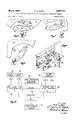
- FIG. 1 is a perspective view of the external housing of an impact-reaction testing machine embodying the present invention and including an auxiliary unit for displaying the computed results of the reaction to impact measured by the testing machine.
- FIG. 2 is a front elevational view with the external housing removed of an impact-reaction testing machine embodying the present invention.
- FIG. 3 is a side elevational view of the machine shown in FIG. 2.
- FIG. 4 is a perspective view of the striker retraction mechanism in its retracted position.
- FIG. 5 is a perspective view of the striker retraction mechanism in its released position wherein it is moved into the path of the ball to be tested.
- FIG. 6 is a side elevational view of a portion of the striker release mechanism in its retracted position.
- FIG. 7 is a side elevational view of a portion of the striker release mechanism at the moment the striker is released.
- FIG. 8 is a side elevational view of a portion of the striker release mechanism in the position it assumes at the time of ball impact.
- FIG. 9' is a perspective view of the ball loading mechanism portion of the apparatus showing a ball loaded in position and ready for firing.
- FIG. 10 is a simplified schematic diagram showing the timing, counting, and computing and display operation of the invention.
- FIGS. 1 and 2 for a general description, it will be seen that the working portions of the device are enclosed in an external housing indicated generally at 10.
- An auxiliary display unit 12 is adapted to be associated with the device and serves the function of visually displaying the coefficient of restitution or other output of the device on a readout or display screen 14.
- one or more golf balls 15 to be tested are loaded through an opening 16 in the housing 10 where they are held in a feed chute (not shown) until picked up by a rotatable ball loader mechanism 18 which serves to pick up a ball and rotate it into position to be dropped on a tee 20 when a LOAD button (not shown) is depressed.
- a striker wheel 22 Positioned immediately adjacent the tee is a striker wheel 22 which, during operation, is continuously rotated at any one of a plurality of predetermined speeds.
- a FIRE" button (not shown) may be depressed to initiate a striker member actuating mechanism which will move the retractable striker member 24 from a retracted position out of the path of the ball into the fully extended position shown in FIG. 2.
- striker member 24 Immediately after the striker member 24 is moved into the path of the ball, it will contact the ball just placed on the tee 20* and cause it to move tangentially relative to the striker wheel and in a path where it will first intercept a beam from photocell 26 and then pass along a path B through a flight tube 27 until it passes through a light screen 28 and against a deflecting surface such as a curtain 30 in a receiving chamber 32.
- a return chute 34 is attached to the receiving chamber 32 and serves to permit the balls to be returned to the opening 36 to permit their removal from the machine.
- the coefl'icient of restitution e of a ball being tested in the machine of the present invention is equal to: T /T 1 where T equals the time required by the ball to travel the distance B" equal to the circumference of the circle S generated by the striker member at the point the striker engages a ball, and T equals the time of one striker revolution.
- the times T and T are measured by counting high frequency time pulses.
- the computing of the coeflicient of restitution is accomplished by a rela tively simple computer of a type which is readily available commercially but not described since it forms no part of the present invention.
- the quantities B and S were chosen equal to 211- feet so that the radius of the striker member at impact was exactly one foot.
- the pulse generator utilized in the test model was crystal controlled at 100,000 I-Iz. resulting, in an accuracy in determining the coefficient of restitution within 2%.
- Ball 15 after being struck by striker 24 interrupts photobeam 26 and starts ball flight time pulse counter 40 counting and conditions the striker time pulse counter 46 to permit it to be able to count.
- the pulses for the counters 4t ⁇ and 46 are provided by a high frequency time pulse generator 42.
- the striker time pulse counter 46 will then count pulses until the striker wheel has made one revolution at which time the single pulse generator 44 coupled to the striker wheel will operate the pulse counter 46 tostop counting at a pulse count equal to T
- the pulse count T will be stored in an electronic register (not shown) where it will be available to the computer for processing.
- the computer 48 calculates the coefiicient of restitution e by dividing the striker pulse count T by the ball flight pulse count T and subtracting the quantity to provide a result equal to the coeflicient of restitution which it then feeds to display 14 for digital readout.
- the counters 40 and 46, the computer 48 and display 14 are all reset to 0 when the LOAD button (not shown) is pushed for the next test cycle.
- the striker wheel 22 (FIGS. 35) is attached to a shaft 50 rotatably mounted in striker support housing 52.
- the striker shaft 50 is rotated by striker drive motor 54 by means of drive belt 56.
- striker drive motor 54 is preferably a variable speed motor capable of driving the striker member 24 and thus the ball is at any desired speed within the range of approximately through 230 feet per second.
- FIGS. 6 through 8 The mechanism for releasing the striker member 24 when a ball 15 has been properly loaded on the tee 20 is set forth in FIGS. 6 through 8. At all times in which the striker Wheel 22 is rotating, other than the cycle of rotation wherein the ball is struck, and a second or so time interval thereafter, the striker member 24 is retracted to the position shown in FIG. 6. Once a ball has been properly loaded and the firing sequence initiated by depressing a FIRE button (not shown) a striker release pawl 60 is rotated from the position shown in FIG. 6 to the position shown in FIG. 7 by means of a rotary solenoid (not shown).
- the tip 61 of the release pawl will move radially outwardly of the striker wheel when it is actuated in a clockwise direction by the rotary solenoid.
- the radially outward movement of the tip 61 relative to the striker wheel will position the tip such that it will be struck by the radially inwardly extending tail portion 62 of the striker release latch 63 mounted on the rotating striker wheel 22.
- the striker release latch 63 will pivot and thereby release its forward tip portion 64 from its engaging relationship with detent shoulder 65 on striker member 24.
- the striker member In order to prepare the machine for the next firing cycle and also to correct the unbalanced condition of the striker wheel which obtains when the striker member 24 is out, the striker member is preferably returned to its retracted position as soon as possible after striking the ball.
- the rotary solenoid which is used to actuate the striker release pawl 60 is operated only momentarily so that the release pawl will be returned to its normal position out of the path of the latch tail portion 62 by the time the striker retracting mechanism has completed its cycle.
- Retraction of the striker member 24 takes place with the mechanism shown in FIGS. 4 and 5. Although the operation of the retraction mechanism is initiated, after a short time delay, with the operation of the FIRE button (not shown), the time period required to complete the retraction is sutficiently long so as to insure that the striker member will be in the fully extended position shown in FIGS. 5 and 8 when brought into contact with the ball.
- the striker member 24 is retracted by a force applied to its inner end 70 by retracting plunger 72 which is reciprocated in plunger support block 73 by means of plunger linkage 74 actuated by axial movement of plunger rod 76.
- the plunger rod 76 is mounted to and reciprocates with slide 78 which is movable in ways 80 in the striker support housing 52 by means of an eccentric (not shown) attached to a latching motor (not shown) positioned about the ways 80.
- the supplying of balls to the machine for testing is accomplished by the ball loading mechanism shown in FIG. 9.
- This mechanism includes a ball cup 86 preferably made of plastic which is adapted to receive one ball at a time from a feed chute (not shown) which exits to the exterior of the housing at opening 16.
- the ball cup is pivoted about axis 90 from its ball receiving position shown in FIG. 9 to a ball discharge position wherein the ball cup is above and adjacent to tee 20.
- a ball support disc 88 fixed for movement with the cup 86 will contact the next ball to be loaded and prevent it from falling out of the feed chute which it is in.
- the back and forth pivoting of the ball cup 86 and support disc 88 about axis 90 between the receiving and discharge positions is accomplished by means of lever 92 which is eccentrically mounted relative to shaft 94 of a ball loading motor (not shown).
- the tee and thus the ball may be moved forwardly and backwardly a limited amount in the direction of the tube 27 along guideways 1 00.
- the movement is preferably provided by a motor and lead screw (not shown).
- a calibrating screen 104 may be inserted in the ball receiving chamber 32.
- the screen 104 is easily made of a penetratable material such as paper.
- the tee 20 may be replaced with one of a different height.
- a very important feature of the invention and one which makes the calculation of the coefiicient of restitution quite simple is the fact that the length of the ball flight path B between the photobeam 26 and the photoscreen 28 is chosen to be equal in length to the circumference S of the path generated by a striker member in one revolution at its point of contact with the ball. More accurately, the length of path S could be defined as 21r times the radius of the ball contacting portion of the striker member 24 at the time of impact since the striker member starts to retract after it strikes the ball.
- the invention has been described with respect to its use for determining the coeflicient of restitution of a ball, it is also effective for permitting the measurement of other factors which are afiected by the manner in which a struck resilient object, such as a golf ball, reacts to impact.
- the invention could be described generally as an impact reaction tester rather than merely a device for determining the coefficient of restitution.
- the computer since the ball length B is fixed, it is possible to program the computer to divide the value of B by the quantity T provided by the pulse counter 40 in order to indicate the ball speed (V attained by the ball at any predetermined impact velocity (V Similarly, the striker S can be indicated at any time by merely actuating the pulse counter 46.
- Apparatus for testing the reaction of a resilient body to an impact applied at a predetermined speed comprismg:
- first and second measuring means comprise first and second pulse counters respectively, said second pulse counter being activated to permit counting when said first pulse counter is activated by the passage of a struck ball past a light beam.
- Apparatus in accordance with claim 1 wherein said means for measuring the time of travel of a resilient body through a predetermined distance comprises light beam means, light screen means spaced from said light beam means by said predetermined distance, and a pulse counter for counting time pulses during the interval in which the resilient body travels said predetermined distance.
- said means for positioning comprises a tee which is mounted for adjustable movement in a generally horizontal direction to permit the point of impact of the striking means with the resilient body to be altered whereby to change the initial flight trajectory of the body after impact.
- said movable striking means comprises a striker member pivotally mounted on said driving member, latch means for normally retaining said striker member in a retracted position, and actuating means for releasing said latch means and permitting said striker member to move to its operative position.
- said means for positioning includes a rotary loading mechanism, said loading mechanism being adapted to receive a resilient body to be tested, to carry it to and drop it on a tee, and to return to a loading position for receipt of another body.
- Apparatus for testing the reaction of a ball to an impact applied at any one of a plurality of velocities at which the ball can be driven comprising:
- Apparatus for measuring the coefficient of restitution of a resilient ball when subjected to impact at any of a plurality of velocities at which the ball can be driven comprising:
- driving means for rotating said member at a selected variable speed; ball striking means in said driving member;
Landscapes
- Physics & Mathematics (AREA)
- Health & Medical Sciences (AREA)
- Life Sciences & Earth Sciences (AREA)
- Chemical & Material Sciences (AREA)
- Analytical Chemistry (AREA)
- Biochemistry (AREA)
- General Health & Medical Sciences (AREA)
- General Physics & Mathematics (AREA)
- Immunology (AREA)
- Pathology (AREA)
- Length Measuring Devices By Optical Means (AREA)
- Investigating Strength Of Materials By Application Of Mechanical Stress (AREA)
Applications Claiming Priority (1)
| Application Number | Priority Date | Filing Date | Title |
|---|---|---|---|
| US72617368A | 1968-05-02 | 1968-05-02 |
Publications (1)
| Publication Number | Publication Date |
|---|---|
| US3509736A true US3509736A (en) | 1970-05-05 |
Family
ID=24917523
Family Applications (1)
| Application Number | Title | Priority Date | Filing Date |
|---|---|---|---|
| US726173A Expired - Lifetime US3509736A (en) | 1968-05-02 | 1968-05-02 | Apparatus for testing impact reaction of resilient bodies |
Country Status (2)
| Country | Link |
|---|---|
| US (1) | US3509736A (https=) |
| GB (1) | GB1225208A (https=) |
Cited By (6)
| Publication number | Priority date | Publication date | Assignee | Title |
|---|---|---|---|---|
| US5245862A (en) * | 1991-12-24 | 1993-09-21 | Zeiss Taylor R | Ball testing device |
| US5672809A (en) * | 1996-02-29 | 1997-09-30 | Brandt; Richard A. | Method and apparatus for determining the performance of sports bats and similar equipment |
| US6571600B2 (en) | 2001-09-19 | 2003-06-03 | Acushnet Company | Apparatus and method for measurement of coefficient of restitution and contact time |
| US6804988B2 (en) | 2001-09-19 | 2004-10-19 | Acushnet Company | Golf ball COR testing machine |
| US20050034506A1 (en) * | 2001-09-19 | 2005-02-17 | Laurent Bissonnette | Golf ball COR testing machine |
| US20060032288A1 (en) * | 2004-08-10 | 2006-02-16 | Diomar Correia | High speed resiliometer |
Citations (3)
| Publication number | Priority date | Publication date | Assignee | Title |
|---|---|---|---|---|
| US2314063A (en) * | 1940-08-31 | 1943-03-16 | Us Golf Ass | Apparatus for testing golf balls |
| US2783999A (en) * | 1954-02-25 | 1957-03-05 | Reflectone Corp | Golf game |
| US3299692A (en) * | 1964-03-19 | 1967-01-24 | Spalding A G & Bros Inc | Velocity measuring and segregating device for propelled articles |
-
1968
- 1968-05-02 US US726173A patent/US3509736A/en not_active Expired - Lifetime
-
1969
- 1969-05-01 GB GB1225208D patent/GB1225208A/en not_active Expired
Patent Citations (3)
| Publication number | Priority date | Publication date | Assignee | Title |
|---|---|---|---|---|
| US2314063A (en) * | 1940-08-31 | 1943-03-16 | Us Golf Ass | Apparatus for testing golf balls |
| US2783999A (en) * | 1954-02-25 | 1957-03-05 | Reflectone Corp | Golf game |
| US3299692A (en) * | 1964-03-19 | 1967-01-24 | Spalding A G & Bros Inc | Velocity measuring and segregating device for propelled articles |
Cited By (8)
| Publication number | Priority date | Publication date | Assignee | Title |
|---|---|---|---|---|
| US5245862A (en) * | 1991-12-24 | 1993-09-21 | Zeiss Taylor R | Ball testing device |
| US5672809A (en) * | 1996-02-29 | 1997-09-30 | Brandt; Richard A. | Method and apparatus for determining the performance of sports bats and similar equipment |
| US6571600B2 (en) | 2001-09-19 | 2003-06-03 | Acushnet Company | Apparatus and method for measurement of coefficient of restitution and contact time |
| US6804988B2 (en) | 2001-09-19 | 2004-10-19 | Acushnet Company | Golf ball COR testing machine |
| US20050034506A1 (en) * | 2001-09-19 | 2005-02-17 | Laurent Bissonnette | Golf ball COR testing machine |
| US7150178B2 (en) | 2001-09-19 | 2006-12-19 | Acushnet Company | Golf ball COR testing machine |
| US20060032288A1 (en) * | 2004-08-10 | 2006-02-16 | Diomar Correia | High speed resiliometer |
| US7127933B2 (en) | 2004-08-10 | 2006-10-31 | Acushnet Company | High speed resiliometer |
Also Published As
| Publication number | Publication date |
|---|---|
| GB1225208A (https=) | 1971-03-17 |
Similar Documents
| Publication | Publication Date | Title |
|---|---|---|
| US5672809A (en) | Method and apparatus for determining the performance of sports bats and similar equipment | |
| US7987693B2 (en) | Method and device for automated electronic green speed measurement | |
| US2111249A (en) | Impact indicator for golf clubs | |
| US2986937A (en) | Lineal yardage meter attachment for golf clubs | |
| US4212193A (en) | Apparatus and method for determining the moment of inertia of golf clubs and like objects | |
| US3509736A (en) | Apparatus for testing impact reaction of resilient bodies | |
| FR2637812A3 (fr) | Analyseur de swing de golf | |
| SU971119A3 (ru) | Способ определени твердости материалов методом упругой отдачи и устройство дл его осуществлени | |
| US5245862A (en) | Ball testing device | |
| US2641458A (en) | Accelerometer | |
| US3444729A (en) | Golf club swinging apparatus | |
| US20060179917A1 (en) | Device and method for measuring the impact properties of a sport field surface | |
| WO1997029817A1 (en) | Apparatus and method for analyzing bowling technique | |
| US5299983A (en) | Double action variable force pool cue | |
| US4885933A (en) | Hardness impact tester | |
| Bufton et al. | Seed displacement after impact on a soil surface | |
| CN214844556U (zh) | 一种撞击感度测试仪 | |
| CN100516806C (zh) | 冲击试验机的直接检定方法和专用标准冲击体 | |
| GB1358131A (en) | Hardness testing | |
| US3469454A (en) | Golf game apparatus | |
| US2778219A (en) | Impact tester for brittle materials | |
| US3136117A (en) | Time interval computing means | |
| US2740287A (en) | Golf ball tester | |
| CN206474440U (zh) | 一种无缝乒乓球弹跳性能检测分选装置 | |
| US2755439A (en) | Bullet velocity measurement |