US3477375A - Piston-primer cartridge - Google Patents
Piston-primer cartridge Download PDFInfo
- Publication number
- US3477375A US3477375A US720549A US3477375DA US3477375A US 3477375 A US3477375 A US 3477375A US 720549 A US720549 A US 720549A US 3477375D A US3477375D A US 3477375DA US 3477375 A US3477375 A US 3477375A
- Authority
- US
- United States
- Prior art keywords
- primer
- piston
- cartridge
- cup
- annular
- Prior art date
- Legal status (The legal status is an assumption and is not a legal conclusion. Google has not performed a legal analysis and makes no representation as to the accuracy of the status listed.)
- Expired - Lifetime
Links
Images

Classifications
-
- F—MECHANICAL ENGINEERING; LIGHTING; HEATING; WEAPONS; BLASTING
- F42—AMMUNITION; BLASTING
- F42B—EXPLOSIVE CHARGES, e.g. FOR BLASTING, FIREWORKS, AMMUNITION
- F42B5/00—Cartridge ammunition, e.g. separately-loaded propellant charges
- F42B5/26—Cartridge cases
- F42B5/36—Cartridge cases modified for housing an integral firing-cap
-
- F—MECHANICAL ENGINEERING; LIGHTING; HEATING; WEAPONS; BLASTING
- F42—AMMUNITION; BLASTING
- F42B—EXPLOSIVE CHARGES, e.g. FOR BLASTING, FIREWORKS, AMMUNITION
- F42B5/00—Cartridge ammunition, e.g. separately-loaded propellant charges
- F42B5/02—Cartridges, i.e. cases with charge and missile
Definitions
- a cartridge having a single-unit movable piston primer for use in automatic and semi-automatic fire-arms which operate on the principle of primer setback.
- the single-unit piston primer is cup-shaped with a 7 Claims circumferential rim-fire rear wall and contains a primer charge.
- the cup-shaped piston primer is open toward the This invention relates to cartridges of the primer setback or piston-primer type.
- a cartridge may be chambered in the barrel, and when the firing pin of the firearm strikes the primer in a forward stroke, a primer charge ignites which, in turn, ignites a propellant to create a high gas pressure that propels a projectile forward from the cartridge casing and through the barrel.
- the high gas pressure also propels the primer rear- Wardly in the direction opposite to the motion of the projectile.
- the rearward movement of the primer imparts energy to the firing pin and drives it rearwardly in a return stroke which operates the breech mechanism to extract the spent cartridge casing, cock the firearm and chamber another cartridge.
- a cartridge which maximizes the amount of energy the piston primer imparts to the firing pin of the firearm during the return stroke. This can best be done by minimizing the amount of energy dissipated by the friction between the piston primer and the cartridge during its rearward movement while at the same time preventing the propellant gas from leaking rearward of the piston primer in a manner which would substantially reduce the differential gas pressure exerted on the piston primer and hence reduce the force driving the piston primer rearward. Furthermore, it is desirable to prevent the piston primer from being blown out the base of the cartridge because the resulting sharp reduction of the propellant gas pressure would substantially reduce the velocity of the projectile and hence afiect the range and accuracy of the weapon. In addition, it is desirable that the piston primer be constructed of as few parts as possible to facilitate the manufacture of the cartridge and reduce the production costs.
- a cartridge having a casing with a pair of interconnected longitudinally arranged coaxial bores, the large-r diameter bore containing a propellant and the smaller diameter bore having a movable cup-shaped piston primer disposed therein which opens toward the interior of the casing and contains a primer mixture adapted to be ignited and fire the propellant in the larger diameter bore.
- the movable cup-shaped piston primer has a relatively thick-walled deformation-resistant tubular wall portion freely slidably engaging the smaller diameter bore with a relatively thinner and more easily deformable base portion extending rearward thereof which is prebent or preshaped to form a circumferential rim anvil or arranged to be easily bent upon being struck by the head of a firing pin to form a circumferential rim anvil which in turn is adapted to ignite the primer charge.
- annular flared obturating flange portion At the open end of the tubular wall portion is formed an annular flared obturating flange portion with only a small circumferential surface area slidably engaging the larger diameter bore in a light interference fit for gas sealing action and maximizing of energy transfer to the piston primer.
- the forward longitudinal movement of the piston primer is limited by a stop formedi n the larger diameter bore for engagement by the forward edge of the flared flange portion of the piston primer, while the rearward longitudinal movement of the piston primer is limited by the engagement of the back side of the flared obturating flange portion with an annular beveled shoulder connecting the coaxial bores.
- the interference fit obturating flange portion has only a small surface area engaging the larger diameter bore, and the thick-walled tubular rear portion of the primer freely slidably engages the smaller diameter bore, the retarding frictional forces incurred during the rearward movement of the piston primer are minimized to enable it to drive the firing pin backward in a return stroke and transfer a maximum amount of energy to operate the breech mechanism, extract the spent cartridge, cock the firearm and chamber another cartridge.
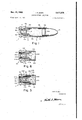
- FIG. 1 shows a longitudinal cut-away view of a cartridge according to the invention.
- FIG. 2 shows the cartridge of FIG. I inserted in the chamber of a firearm with a bolt engaging the base of the cartridge and having a firing pin in the ready position.
- FIG. 3 is a view similar to FIG. 2, showing the firing pin shortly after striking the base of the primer and igniting the propellant to provide the projectile-propelling high gas pressure.
- FIG. 4 is a view similar to FIGS. 2 and 3, showing the movable primer propelled rearward by the propellant gas pressure which forces the firing pin backward in a return stroke.
- FIG. 5 illustrates a second embodiment according to the invention, incorporating a two-piece single-unit piston primer having a thin, easily deformable, outer cup portion surrounding a relatively thick-walled inner reinforcing member which is open at both ends and serves as a circumferential anvil, cylindrical guide section reinforcement, and obturating element.
- FIG. 6 illustrates a third embodiment according to the invention, incorporating a single-unit cup-shaped piston primer composed of a single piece, the rear section of which is preformed as a self-forming circumferential rim hammer and anvil.
- FIG. 1 a cartridge suitable for use in a gun which is operated on the primer set-back and energy transfer principle.
- the cartridge generally indicated at 11, includes a casing, generally indicated at 13, containing a movable single-unit piston primer, generally indicated at 15, a projectile 21 and propellant 31 disposed between the movable piston primer 15 and the projectile 21.
- the cartridge casing 13 has two coaxial bores of different diameters, indicated respectively at 13b and 13d, and connected through an annular beveled shoulder 130, with the smaller guide bore 13d being located at the rear of the cartridge casing 13 and the larger gas-retaining bore 13b being located at the forward end of the casing 13 and adapted to securely grip an annular groove 21a of the projectile 21 by means of an annular indentation 13c.
- the single-unit, cup-shaped, piston primer 15 has a cylindrical piston guiding portion 15a opening forwardly toward the interior of the larger diameter propellant chamber bore 13b with an annular, flared, obturating, flange portion 15d formed at the open mouthed forward end thereof.
- the cylindrical guide portion 15a has an integrally connected, thin-walled rear or base cup portion 15b which is of smaller diameter than the cylindrical guide portion 15a.
- An external annular shoulder 150 is formed at the junction of the base cup portion 15b and the cylindrical guide portion 15a, this shoulder serving as an effective circumferential anvil when the base cup portion is crushed against it upon being struck by the firing pin and further serves, in conjunction with the firing pin, to provide a tight fitting internal chamber seal to prevent the relatively thin-walled base cup from being laterally ruptured by the high gas pressure resulting from ignition of the propellant.
- the cylindrical piston guiding portion 15a of the primer 15 is freely slidably disposed in the small diameter bore 13d at the rear of the cartridge casing 13 while the edge of the flared flange portion 15d slidably engages the larger diameter bore 13b in a light interference fit. In its unfired position, the edge of the flared flanged portion 15d engages an annular forward shoulder stop as shown at 13a, or alternatively, circumferentially spaced dimple stops, which limits the forward motion of the primer piston.
- the primer charge 17 which may be of conventional composition, and which is separated from the propellant 31 near the open-mouthed end of the cup-shaped piston by only a thin easily frangible and preferably combustible moisture seal 19 of suitable material such as a coating of wax or Krylon. While the moisture seal 19 is not absolutely required for functional operation, it is desirable to aid against malfunction due to undesired moisture absorption by the primer mix which, for example, might occur during assembly.
- FIGS. 24 is illustrated the operation of the cartridge shown in FIG. 1.
- a cartridge is shown inserted in a chamber 41a of a conventional barrel 41 having a bore 43 with a bolt 51 pressed against the base of the cartridge casing 13 and having the finger 52a of an extractor 52 engaging an extractor groove 13 formed in the rear of the cartridge casing 13.
- a firing pin 61 Disposed inside the bolt 51 is a firing pin 61 having a head 61a for striking the deformable, cup-shaped base 15! of the cup-shaped piston primer 15 so as to cause ignition of the primer charge 17 and the propellant charge 31.
- FIG. 3 is shown the head 61a of the firing pin 61 striking the base 15b of the piston primer 15 at the end of a forward stroke.
- the base 15b of the piston primer 15a is crushed and pressed against the end of the external annular shoulder 15c at the end of the relatively thickwalled cylindrical portion, which effectively forms a circumferential rim anvil, thereby igniting the primer charge.
- the head 61a of the firing pin 61 and the external annular shoulder 15c coact to provide a seal which prevents any lateral rupture of the thin-walled base 15b of the cup-shaped primer.
- the ignition of the primer charge 17 ignites the propellant charge 31, which generates a high gas pressure that propels the projectile 21 and at the same time obturates the flared annular flange 15d of the primer 15 against the large diameter bore 13b of the cartridge casing 130 and thereby prevents gas leakage to the rear of the flange portion 15d.
- the cylindrical guide portion substantially resists expansion from the high gas pressure upon ignition of the propellant 31, and remains easily slidable within the small diameter bore to deliver a maximum amount of force to the firing pin 61 to drive it backward in a return stroke.
- the single-unit piston primer is propelled backwards by the high gas pressure to the rear of the cartridge casing 13 until the back side of the flanged portion 15d engages the annular, beveled shoulder 130 which stops the rearward longitudinal movement of the piston primer 15, as shown in FIG. 4.
- the high gas pressure forces the thin-walled base 15b of the cup-shaped piston to bulge rearwardly in a semispherical shape.
- the rearward motion of the cup-shaped piston primer 15 forces the firing pin 61 backward in a rearward return stroke to opeate the breech mechanism and/ or other components of the firearm.
- the movable primer is composed of two unitarily connected pieces 115a and 115b.
- the first piece 115a is cup-shaped and relatively thin-walled and forms the annular exterior of the primer 115, which has a rear surface portion 115s which is formed by the thinner walled piece 115a and which slidably engages a small diameter bore 113d at the base of the cartridge casing 113 in a loose sliding fit.
- annular outwardly flared flanged portion 115a is formed at the open end of the cup-shaped piece 115a, the annular lip of which slidably engages the large diameter bore of the cartridge casing in a light interference fit.
- annular member 115b Secured tightly within the thin-walled piece 115a is an annular member 115b having a bore coaxial with the cup-shaped portion of the thin-walled piece 115a and an outer annular surface which is contiguous with the interior surface of the thin-walled piece 115a.
- the inner member 11512 has a relatively thickwalled, cylindrical section 115])" for annular reinforcement of thinner-walled section 115a" forming the rear surface portion 1150.
- an outwardly flared flange 1151 is also formed at the forward open end of the inner cylindrical member 1151') at the forward open end of the inner cylindrical member 1151'.
- the outer lip of which is substantially thinner than cylindrical wall section 115b", and which in conjunction with the contiguous lip of the annular flange 115a, serves as a pressure responsive obturator seal.
- the thick-walled member 115b is contained within the thin-walled member 115a the longitudinal extent of the thick-walled member is less than that of the thin-walled member 115a to form a rim-like cavity between the base of the thin-walled member 115a and the rear end surface of the thick-walled member 115b.
- the primer charge 117 is contained in the bore of the thickwalled member 115b and in the cavity between the base of the thin-walled member 115a and the edge of the thick-walled member 115b and it is separated from the propellant 131 by an easily frangible moisture seal 119.
- the cartridge casing 113 has the same general configuration as the cartridge casing in FIG.
- FIG. 6 is shown still another embodiment, generally indicated at 211, in which the cup-shaped piston primer 215 is composed of a single piece having a cylindrical guide portion 215a which freely slidably engages the small diameter bore in the base of the cartridge casing with an annular, outwardly flared, flanged obturator portion 215b, the annular obturator lip 2151) of which slidably engages the large diameter bore of the cartridge casing in a light interference fit.
- the cup-shaped piston primer 215 is composed of a single piece having a cylindrical guide portion 215a which freely slidably engages the small diameter bore in the base of the cartridge casing with an annular, outwardly flared, flanged obturator portion 215b, the annular obturator lip 2151) of which slidably engages the large diameter bore of the cartridge casing in a light interference fit.
- the central tubular wall of the cylindrical, piston portion 215a is relatively thick for radial strength, and has a relatively thin-walled base 2150 which protrudes rearwardly and bulges radially from the annular shoulder 215a, as indicated at 2150', at the rear end of the thick-walled tubular section 215a to form an annular rim chamber 215d.
- a primer charge 217 which is separated from the propellant charge 231 contained in the interior of the cartridge casing 213 by only a thin, easily frangible preferably combustible, moisture seal 219 of suitable material such as wax or Krylon.
- the thinwalled overlapping base 2150 Upon being struck by the head of a firing pin at the end of its forward stroke, the thinwalled overlapping base 2150 is crushed and the bulging annular rim section 215d is pressed against the end of the thick tubular wall 215a which serves as a circumferential anvil to pinch a portion of the primer charge 217a between the bulging or overlapping rim portions 215d of the thin-walled base 215a, thereby igniting the primer charge 217, which in turn ignites the propellant 231 contained in the interior of the cartridge casing to effect forward motion of the projectile and rearward energy transfer motion of the piston primer 215, as hereinbefore described in relation to the cartridge shown in FIG. 1.
- a cartridge of the primer set-back type including a casing having an open forward end with a projectile p engage the forward stop retaining means and with a base portion rearward of the tubular wall portion being relatively thinner and more deformable than the tubular portion and adapted to be deformed and 'pressed against the rearward end of the relatively thick tubular portion upon being struck by the head of a firing pin to effect percussion firing of the primer mixture contained therein.
- the improvement further comprising:
- said cartridge casing having a second bore formed therein of larger diameter and coaxial with the first bore and connected thereto by an annular beveled shoulder and adapted to contain the propellant there- 1n, an annular flared flange portion formed at the open end of the cup-shaped piston primer and disposed in the larger diameter bore in the cartridge casing with the sides of the flanged portion engaging the larger diameter bore in a light interference fit and adapted to obturate upon ignition of the propellant to form a seal against the rearward leakage of the resulting propellant gas through the bore in the base of the cartridge.
- cup-shaped piston primer having a unitary construction with its base portion extending rearwardly from the relatively thicker and less deformable tubular wall portion and having a common interior diameter therewith but being adapted to be readily deformed and pressed against the end of the relatively thicker tubular wall upon being struck by the head of a firing pin to form a circumferential anvil to ignite the primer mixture contained therein.
- cup-shaped piston primer having a unitary construction with the base portion outwardly from the rearward interior portion of the relatively thicker and relatively less deformable tubular wall to form an overlap which serves as a circumferential anvil adapted to be readily deformed and pressed against the end of the relatively thicker tubular wall upon being struck by the head of a firing pin to ignite the primer mixture contained therein.
- cup-shaped piston primer being formed by a tubular wall disposed inside a relatively thinner and more deformable cup-shaped member with the rearward portion of the relatively thinner and more derearward end of the relatively thicker and relatively formable cup-shaped member extending beyond the References Cited UNITED STATES PATENTS less deformable tubular wall to form a cavity adapted 624 146 5/1899 Young 102 38 to be readily deformed and pressed against the rear- 740:790 10/1903 Young et aL 102 45 ward end of the relatively thicker tubular wall which 5 2 394,249 2 194 McG-ahey 102 3 serves as a circumferential anvil upon being struck 2,537,443 1/1951 cerrella 89-156 by the head of a firing pin to ignite the primer mixture contained therein ROBERT F. STAHL, Primary Examiner
Landscapes
- Engineering & Computer Science (AREA)
- General Engineering & Computer Science (AREA)
- Portable Nailing Machines And Staplers (AREA)
Description
Nov. 11, 1969 I. R. BARR 3,477,375
PISTON-PRIMER CARTRIDGE Filed April 11. 1968 2 sheets sheeft"l Ir win R. Barr INVENTOR glam/7w ATTORNEY Nov. 11, 1969 l. R. BARR 3,477,375
uswowmmm CARTRIDGE 7 Filed April 11, 1968 2 Sheets-Sheet 2 ATTORNEY United States Patent ()lfice 3,477,375 Patented Nov. 11, 1969 3,477,375 PISTON-PRIMER CARTRIDGE Irwin R. Barr, Lutherville, Md., assignor to AAI Corporation, Cockeysville, Md., a corporation of Maryland Filed Apr. 11, 1968, Ser. No. 720,549' Int. Cl. F42b 5/28 US. Cl. 102-45 ABSTRACT OF THE DISCLOSURE A cartridge is disclosed having a single-unit movable piston primer for use in automatic and semi-automatic fire-arms which operate on the principle of primer setback. The single-unit piston primer is cup-shaped with a 7 Claims circumferential rim-fire rear wall and contains a primer charge. The cup-shaped piston primer is open toward the This invention relates to cartridges of the primer setback or piston-primer type.
In automatic or semi-automatic firearms utilizing primer set-back cartridges for operation, a cartridge may be chambered in the barrel, and when the firing pin of the firearm strikes the primer in a forward stroke, a primer charge ignites which, in turn, ignites a propellant to create a high gas pressure that propels a projectile forward from the cartridge casing and through the barrel. The high gas pressure also propels the primer rear- Wardly in the direction opposite to the motion of the projectile. The rearward movement of the primer imparts energy to the firing pin and drives it rearwardly in a return stroke which operates the breech mechanism to extract the spent cartridge casing, cock the firearm and chamber another cartridge.
To obtain the most effective operation of a primer setback arrangement, it is necessary to use a cartridge which maximizes the amount of energy the piston primer imparts to the firing pin of the firearm during the return stroke. This can best be done by minimizing the amount of energy dissipated by the friction between the piston primer and the cartridge during its rearward movement while at the same time preventing the propellant gas from leaking rearward of the piston primer in a manner which would substantially reduce the differential gas pressure exerted on the piston primer and hence reduce the force driving the piston primer rearward. Furthermore, it is desirable to prevent the piston primer from being blown out the base of the cartridge because the resulting sharp reduction of the propellant gas pressure would substantially reduce the velocity of the projectile and hence afiect the range and accuracy of the weapon. In addition, it is desirable that the piston primer be constructed of as few parts as possible to facilitate the manufacture of the cartridge and reduce the production costs.
Accordingly, it is a feature of the present invention to provide a cartridge of the primer set-back type wherein frictional retarding forces on the piston primer during its rearward movement are minimized while efliciently translating propellant gas pressure action into rearward driving force on the piston primer; thereby enabling a maximum driving force to be imparted to the firing pin of the firearm during the return stroke, while also providing a gas seal to prevent the rearward leakage of the high pressure propellant gas to further maximize the amount of force exerted on the piston primer.
It is another feature of the present invention to provide a piston primer in which an obturating gas seal on the piston primer is adapted to engage the cartridge casing at the end of the rearward driving movement to prevent the piston primer from being blown out the base of the cartridge by the propellant gas forces.
It is a further feature of the present invention to provide a piston primer having a simple, compact, and unitary construction to facilitate the manufacture of the cartridge and reduce the production costs.
In accordance with the present invention, a cartridge is provided having a casing with a pair of interconnected longitudinally arranged coaxial bores, the large-r diameter bore containing a propellant and the smaller diameter bore having a movable cup-shaped piston primer disposed therein which opens toward the interior of the casing and contains a primer mixture adapted to be ignited and fire the propellant in the larger diameter bore. The movable cup-shaped piston primer has a relatively thick-walled deformation-resistant tubular wall portion freely slidably engaging the smaller diameter bore with a relatively thinner and more easily deformable base portion extending rearward thereof which is prebent or preshaped to form a circumferential rim anvil or arranged to be easily bent upon being struck by the head of a firing pin to form a circumferential rim anvil which in turn is adapted to ignite the primer charge. At the open end of the tubular wall portion is formed an annular flared obturating flange portion with only a small circumferential surface area slidably engaging the larger diameter bore in a light interference fit for gas sealing action and maximizing of energy transfer to the piston primer. The forward longitudinal movement of the piston primer is limited by a stop formedi n the larger diameter bore for engagement by the forward edge of the flared flange portion of the piston primer, while the rearward longitudinal movement of the piston primer is limited by the engagement of the back side of the flared obturating flange portion with an annular beveled shoulder connecting the coaxial bores.
When the head of a firing pin strikes the base of the cup-shaped piston primer at the end of a forward stroke, the circumferential rim anvil is crushed to ignite the primer charge which in turn fires the propellant to create a high gas pressure that propels a projectile from the cartridge while at the same time acting across the full cross-sectional area of the open end of the piston primer which occupies the full cross-sectional area of the larger diameter propellant-containing bore to impart a maximum rearward force to the piston primer to drive it rearwardly. Because the interference fit obturating flange portion has only a small surface area engaging the larger diameter bore, and the thick-walled tubular rear portion of the primer freely slidably engages the smaller diameter bore, the retarding frictional forces incurred during the rearward movement of the piston primer are minimized to enable it to drive the firing pin backward in a return stroke and transfer a maximum amount of energy to operate the breech mechanism, extract the spent cartridge, cock the firearm and chamber another cartridge.
Still other objects, features, and attendant advantages will become apparent to those skilled in the art from a reading of the following detailed description of several physical embodiments constructed in accordance with the present invention, taken in conjunction with the accompanying drawings wherein:
FIG. 1 shows a longitudinal cut-away view of a cartridge according to the invention.
FIG. 2 shows the cartridge of FIG. I inserted in the chamber of a firearm with a bolt engaging the base of the cartridge and having a firing pin in the ready position.
FIG. 3 is a view similar to FIG. 2, showing the firing pin shortly after striking the base of the primer and igniting the propellant to provide the projectile-propelling high gas pressure.
FIG. 4 is a view similar to FIGS. 2 and 3, showing the movable primer propelled rearward by the propellant gas pressure which forces the firing pin backward in a return stroke.
FIG. 5 illustrates a second embodiment according to the invention, incorporating a two-piece single-unit piston primer having a thin, easily deformable, outer cup portion surrounding a relatively thick-walled inner reinforcing member which is open at both ends and serves as a circumferential anvil, cylindrical guide section reinforcement, and obturating element.
FIG. 6 illustrates a third embodiment according to the invention, incorporating a single-unit cup-shaped piston primer composed of a single piece, the rear section of which is preformed as a self-forming circumferential rim hammer and anvil.
Referring now in detail to the figures of the drawings, in FIG. 1 is shown a cartridge suitable for use in a gun which is operated on the primer set-back and energy transfer principle. The cartridge, generally indicated at 11, includes a casing, generally indicated at 13, containing a movable single-unit piston primer, generally indicated at 15, a projectile 21 and propellant 31 disposed between the movable piston primer 15 and the projectile 21. The cartridge casing 13 has two coaxial bores of different diameters, indicated respectively at 13b and 13d, and connected through an annular beveled shoulder 130, with the smaller guide bore 13d being located at the rear of the cartridge casing 13 and the larger gas-retaining bore 13b being located at the forward end of the casing 13 and adapted to securely grip an annular groove 21a of the projectile 21 by means of an annular indentation 13c. The single-unit, cup-shaped, piston primer 15 has a cylindrical piston guiding portion 15a opening forwardly toward the interior of the larger diameter propellant chamber bore 13b with an annular, flared, obturating, flange portion 15d formed at the open mouthed forward end thereof. The cylindrical guide portion 15a has an integrally connected, thin-walled rear or base cup portion 15b which is of smaller diameter than the cylindrical guide portion 15a. An external annular shoulder 150 is formed at the junction of the base cup portion 15b and the cylindrical guide portion 15a, this shoulder serving as an effective circumferential anvil when the base cup portion is crushed against it upon being struck by the firing pin and further serves, in conjunction with the firing pin, to provide a tight fitting internal chamber seal to prevent the relatively thin-walled base cup from being laterally ruptured by the high gas pressure resulting from ignition of the propellant.
The cylindrical piston guiding portion 15a of the primer 15 is freely slidably disposed in the small diameter bore 13d at the rear of the cartridge casing 13 while the edge of the flared flange portion 15d slidably engages the larger diameter bore 13b in a light interference fit. In its unfired position, the edge of the flared flanged portion 15d engages an annular forward shoulder stop as shown at 13a, or alternatively, circumferentially spaced dimple stops, which limits the forward motion of the primer piston. Compacted in the cup-shaped cylindrical portion 15a is the primer charge 17, which may be of conventional composition, and which is separated from the propellant 31 near the open-mouthed end of the cup-shaped piston by only a thin easily frangible and preferably combustible moisture seal 19 of suitable material such as a coating of wax or Krylon. While the moisture seal 19 is not absolutely required for functional operation, it is desirable to aid against malfunction due to undesired moisture absorption by the primer mix which, for example, might occur during assembly.
In FIGS. 24 is illustrated the operation of the cartridge shown in FIG. 1. In FIG. 2, a cartridge is shown inserted in a chamber 41a of a conventional barrel 41 having a bore 43 with a bolt 51 pressed against the base of the cartridge casing 13 and having the finger 52a of an extractor 52 engaging an extractor groove 13 formed in the rear of the cartridge casing 13. Disposed inside the bolt 51 is a firing pin 61 having a head 61a for striking the deformable, cup-shaped base 15!) of the cup-shaped piston primer 15 so as to cause ignition of the primer charge 17 and the propellant charge 31.
In FIG. 3 is shown the head 61a of the firing pin 61 striking the base 15b of the piston primer 15 at the end of a forward stroke. The base 15b of the piston primer 15a is crushed and pressed against the end of the external annular shoulder 15c at the end of the relatively thickwalled cylindrical portion, which effectively forms a circumferential rim anvil, thereby igniting the primer charge. In addition, the head 61a of the firing pin 61 and the external annular shoulder 15c coact to provide a seal which prevents any lateral rupture of the thin-walled base 15b of the cup-shaped primer. The ignition of the primer charge 17 ignites the propellant charge 31, which generates a high gas pressure that propels the projectile 21 and at the same time obturates the flared annular flange 15d of the primer 15 against the large diameter bore 13b of the cartridge casing 130 and thereby prevents gas leakage to the rear of the flange portion 15d. With the relatively thick-walled construction of the cylindrical piston portion 15c, the cylindrical guide portion substantially resists expansion from the high gas pressure upon ignition of the propellant 31, and remains easily slidable within the small diameter bore to deliver a maximum amount of force to the firing pin 61 to drive it backward in a return stroke.
The single-unit piston primer is propelled backwards by the high gas pressure to the rear of the cartridge casing 13 until the back side of the flanged portion 15d engages the annular, beveled shoulder 130 which stops the rearward longitudinal movement of the piston primer 15, as shown in FIG. 4. In addition, the high gas pressure forces the thin-walled base 15b of the cup-shaped piston to bulge rearwardly in a semispherical shape. The rearward motion of the cup-shaped piston primer 15 forces the firing pin 61 backward in a rearward return stroke to opeate the breech mechanism and/ or other components of the firearm.
In FIG. 5 is shown another embodiment of a cartridge suitable for use in a firearm employing the primer setback and energy transfer principle. In this embodiment, generally indicated at 111, the movable primer is composed of two unitarily connected pieces 115a and 115b. The first piece 115a is cup-shaped and relatively thin-walled and forms the annular exterior of the primer 115, which has a rear surface portion 115s which is formed by the thinner walled piece 115a and which slidably engages a small diameter bore 113d at the base of the cartridge casing 113 in a loose sliding fit. An annular outwardly flared flanged portion 115a is formed at the open end of the cup-shaped piece 115a, the annular lip of which slidably engages the large diameter bore of the cartridge casing in a light interference fit. Secured tightly within the thin-walled piece 115a is an annular member 115b having a bore coaxial with the cup-shaped portion of the thin-walled piece 115a and an outer annular surface which is contiguous with the interior surface of the thin-walled piece 115a. The inner member 11512 has a relatively thickwalled, cylindrical section 115])" for annular reinforcement of thinner-walled section 115a" forming the rear surface portion 1150. Also formed at the forward open end of the inner cylindrical member 1151') is an outwardly flared flange 1151;, the outer lip of which is substantially thinner than cylindrical wall section 115b", and which in conjunction with the contiguous lip of the annular flange 115a, serves as a pressure responsive obturator seal.
Although the thick-walled member 115b is contained within the thin-walled member 115a the longitudinal extent of the thick-walled member is less than that of the thin-walled member 115a to form a rim-like cavity between the base of the thin-walled member 115a and the rear end surface of the thick-walled member 115b. The primer charge 117 is contained in the bore of the thickwalled member 115b and in the cavity between the base of the thin-walled member 115a and the edge of the thick-walled member 115b and it is separated from the propellant 131 by an easily frangible moisture seal 119. The cartridge casing 113 has the same general configuration as the cartridge casing in FIG. 1 with the exception of an annular crimp dimple 11311 in the larger diameter bore 113b, which results in an annular indentation 1131) being formed on the exterior of the cartridge casing that limits the forward longitudinal movement of the primer. Upon being struck by the head of a firing pin 61 at the end of a forward stroke, the base of the thin-walled member 115a is crushed forwardly and pressed against the end of the thick-walled member 115b which serves as a circumferential anvil to pinch a portion of the primer charge 117a therebetween to ignite the primer charge which in turn fires the propellant contained in the larger forward bore, and is thereupon moved rearwardly in substantially the same manner as hereinbefore described in relation to the cartridge shown in FIG. 1.
In FIG. 6 is shown still another embodiment, generally indicated at 211, in which the cup-shaped piston primer 215 is composed of a single piece having a cylindrical guide portion 215a which freely slidably engages the small diameter bore in the base of the cartridge casing with an annular, outwardly flared, flanged obturator portion 215b, the annular obturator lip 2151) of which slidably engages the large diameter bore of the cartridge casing in a light interference fit. The central tubular wall of the cylindrical, piston portion 215a is relatively thick for radial strength, and has a relatively thin-walled base 2150 which protrudes rearwardly and bulges radially from the annular shoulder 215a, as indicated at 2150', at the rear end of the thick-walled tubular section 215a to form an annular rim chamber 215d. Compacted in the rear and central zone of the cup-shaped piston 215 is a primer charge 217 which is separated from the propellant charge 231 contained in the interior of the cartridge casing 213 by only a thin, easily frangible preferably combustible, moisture seal 219 of suitable material such as wax or Krylon. Upon being struck by the head of a firing pin at the end of its forward stroke, the thinwalled overlapping base 2150 is crushed and the bulging annular rim section 215d is pressed against the end of the thick tubular wall 215a which serves as a circumferential anvil to pinch a portion of the primer charge 217a between the bulging or overlapping rim portions 215d of the thin-walled base 215a, thereby igniting the primer charge 217, which in turn ignites the propellant 231 contained in the interior of the cartridge casing to effect forward motion of the projectile and rearward energy transfer motion of the piston primer 215, as hereinbefore described in relation to the cartridge shown in FIG. 1.
That which is claimed is:
1. In a cartridge of the primer set-back type including a casing having an open forward end with a projectile p engage the forward stop retaining means and with a base portion rearward of the tubular wall portion being relatively thinner and more deformable than the tubular portion and adapted to be deformed and 'pressed against the rearward end of the relatively thick tubular portion upon being struck by the head of a firing pin to effect percussion firing of the primer mixture contained therein. 2. In a cartridge of the primer set-back type according to claim 1, the improvement further comprising:
said cartridge casing having a second bore formed therein of larger diameter and coaxial with the first bore and connected thereto by an annular beveled shoulder and adapted to contain the propellant there- 1n, an annular flared flange portion formed at the open end of the cup-shaped piston primer and disposed in the larger diameter bore in the cartridge casing with the sides of the flanged portion engaging the larger diameter bore in a light interference fit and adapted to obturate upon ignition of the propellant to form a seal against the rearward leakage of the resulting propellant gas through the bore in the base of the cartridge. 3. In a cartridge of the primer set-back type according to claim 2 wherein:
the edge of said annular flared flange portion having a thickness substantially less than the thickness of the tubular wall portion. 4. In a cartridge of the primer set-back type according to claim 2 wherein:
the back side of the flared flanged portion formed at the open end of the cupshaped piston primer being adapted to engage the annular beveled. shoulder connecting the coaxial bores formed in the casing to limit the rearward movement of the cup-shaped piston primer upon ignition of the propellant charge, and the forward end of the flared flange portion of the cup-shaped piston primer engaging the forward stop retaining means to limit the forward motion of the piston primer upon being struck by the head of a firing pin. 5. In a cartridge of the primer set-back type according to claim 3:
said cup-shaped piston primer having a unitary construction with its base portion extending rearwardly from the relatively thicker and less deformable tubular wall portion and having a common interior diameter therewith but being adapted to be readily deformed and pressed against the end of the relatively thicker tubular wall upon being struck by the head of a firing pin to form a circumferential anvil to ignite the primer mixture contained therein. 6. In a cartridge of the primer set-back type according to claim 3 wherein:
said cup-shaped piston primer having a unitary construction with the base portion outwardly from the rearward interior portion of the relatively thicker and relatively less deformable tubular wall to form an overlap which serves as a circumferential anvil adapted to be readily deformed and pressed against the end of the relatively thicker tubular wall upon being struck by the head of a firing pin to ignite the primer mixture contained therein. 7. In a cartridge of the primer set-back type according to claim 3 wherein:
said cup-shaped piston primer being formed by a tubular wall disposed inside a relatively thinner and more deformable cup-shaped member with the rearward portion of the relatively thinner and more derearward end of the relatively thicker and relatively formable cup-shaped member extending beyond the References Cited UNITED STATES PATENTS less deformable tubular wall to form a cavity adapted 624 146 5/1899 Young 102 38 to be readily deformed and pressed against the rear- 740:790 10/1903 Young et aL 102 45 ward end of the relatively thicker tubular wall which 5 2 394,249 2 194 McG-ahey 102 3 serves as a circumferential anvil upon being struck 2,537,443 1/1951 cerrella 89-156 by the head of a firing pin to ignite the primer mixture contained therein ROBERT F. STAHL, Primary Examiner
Applications Claiming Priority (1)
| Application Number | Priority Date | Filing Date | Title |
|---|---|---|---|
| US72054968A | 1968-04-11 | 1968-04-11 |
Publications (1)
| Publication Number | Publication Date |
|---|---|
| US3477375A true US3477375A (en) | 1969-11-11 |
Family
ID=24894393
Family Applications (1)
| Application Number | Title | Priority Date | Filing Date |
|---|---|---|---|
| US720549A Expired - Lifetime US3477375A (en) | 1968-04-11 | 1968-04-11 | Piston-primer cartridge |
Country Status (1)
| Country | Link |
|---|---|
| US (1) | US3477375A (en) |
Cited By (14)
| Publication number | Priority date | Publication date | Assignee | Title |
|---|---|---|---|---|
| US5492063A (en) * | 1990-03-22 | 1996-02-20 | Snc Industrial Technologies Inc. | Reduced energy cartridge |
| US5677505A (en) * | 1990-03-22 | 1997-10-14 | Dittrich; William A. | Reduced energy cartridge |
| WO1998041810A1 (en) * | 1997-03-14 | 1998-09-24 | Defense Tech Corp America | Improvements relating to pyrotechnic ammunition |
| US6095051A (en) * | 1998-08-13 | 2000-08-01 | Saxby; Michael Ernest | Self loading gun cartridge |
| US6371028B2 (en) | 1998-10-26 | 2002-04-16 | Michael Ernest Saxby | Projectiles |
| US6378439B1 (en) | 1999-02-01 | 2002-04-30 | Michael Ernest Saxby | Marker projectile |
| US6415718B1 (en) | 1999-08-27 | 2002-07-09 | Lambeth Properties Limited | Training cartridge for a self loading gun |
| US6422149B1 (en) | 1999-08-27 | 2002-07-23 | Lambath Properties Limited | Blank training cartridge for a self loading gun |
| US6427600B2 (en) | 1998-09-14 | 2002-08-06 | Michael Ernest Saxby | Blank cartridge for self loading guns |
| US6564719B2 (en) | 1999-08-27 | 2003-05-20 | Lambeth Properties Limited | Training cartridge for a self loading gun |
| US20070234923A1 (en) * | 1999-10-25 | 2007-10-11 | Mark A. Westrom | Cartridge for a firearm |
| US20140196625A1 (en) * | 2013-01-14 | 2014-07-17 | Pdt Tech, Llc | Low Energy Mechanical Operating Cartridge |
| US20150192394A1 (en) * | 2014-01-09 | 2015-07-09 | Randy R. Fritz | Hollow Slug and Casing |
| US9658038B1 (en) * | 2017-01-18 | 2017-05-23 | James Dunnam | Ammunition cartridge |
Citations (4)
| Publication number | Priority date | Publication date | Assignee | Title |
|---|---|---|---|---|
| US624146A (en) * | 1899-05-02 | Cartridge | ||
| US740790A (en) * | 1903-02-11 | 1903-10-06 | American Automatic Arms Company | Cartridge. |
| US2394249A (en) * | 1941-12-23 | 1946-02-05 | Mcgahey Mfg Company | Cartridge |
| US2537443A (en) * | 1948-08-18 | 1951-01-09 | Cerrella Vicente | Device for operating the movable mechanism of firearms |
-
1968
- 1968-04-11 US US720549A patent/US3477375A/en not_active Expired - Lifetime
Patent Citations (4)
| Publication number | Priority date | Publication date | Assignee | Title |
|---|---|---|---|---|
| US624146A (en) * | 1899-05-02 | Cartridge | ||
| US740790A (en) * | 1903-02-11 | 1903-10-06 | American Automatic Arms Company | Cartridge. |
| US2394249A (en) * | 1941-12-23 | 1946-02-05 | Mcgahey Mfg Company | Cartridge |
| US2537443A (en) * | 1948-08-18 | 1951-01-09 | Cerrella Vicente | Device for operating the movable mechanism of firearms |
Cited By (18)
| Publication number | Priority date | Publication date | Assignee | Title |
|---|---|---|---|---|
| US5492063A (en) * | 1990-03-22 | 1996-02-20 | Snc Industrial Technologies Inc. | Reduced energy cartridge |
| US5677505A (en) * | 1990-03-22 | 1997-10-14 | Dittrich; William A. | Reduced energy cartridge |
| WO1998041810A1 (en) * | 1997-03-14 | 1998-09-24 | Defense Tech Corp America | Improvements relating to pyrotechnic ammunition |
| US6253682B1 (en) | 1997-03-14 | 2001-07-03 | Michael Ernest Saxby | Relating to pyrotechnic ammunition |
| US6095051A (en) * | 1998-08-13 | 2000-08-01 | Saxby; Michael Ernest | Self loading gun cartridge |
| US6427600B2 (en) | 1998-09-14 | 2002-08-06 | Michael Ernest Saxby | Blank cartridge for self loading guns |
| US6371028B2 (en) | 1998-10-26 | 2002-04-16 | Michael Ernest Saxby | Projectiles |
| US6378439B1 (en) | 1999-02-01 | 2002-04-30 | Michael Ernest Saxby | Marker projectile |
| US6422149B1 (en) | 1999-08-27 | 2002-07-23 | Lambath Properties Limited | Blank training cartridge for a self loading gun |
| US6415718B1 (en) | 1999-08-27 | 2002-07-09 | Lambeth Properties Limited | Training cartridge for a self loading gun |
| US6564719B2 (en) | 1999-08-27 | 2003-05-20 | Lambeth Properties Limited | Training cartridge for a self loading gun |
| US20070234923A1 (en) * | 1999-10-25 | 2007-10-11 | Mark A. Westrom | Cartridge for a firearm |
| US7458322B2 (en) | 1999-10-25 | 2008-12-02 | Mark A. Westrom | Cartridge for a firearm |
| US20140196625A1 (en) * | 2013-01-14 | 2014-07-17 | Pdt Tech, Llc | Low Energy Mechanical Operating Cartridge |
| US9534877B2 (en) * | 2013-01-14 | 2017-01-03 | Pdt Tech, Llc | Low energy mechanical operating cartridge |
| US20150192394A1 (en) * | 2014-01-09 | 2015-07-09 | Randy R. Fritz | Hollow Slug and Casing |
| US9395163B2 (en) * | 2014-01-09 | 2016-07-19 | Randy R. Fritz | Hollow slug and casing |
| US9658038B1 (en) * | 2017-01-18 | 2017-05-23 | James Dunnam | Ammunition cartridge |
Similar Documents
| Publication | Publication Date | Title |
|---|---|---|
| US4686905A (en) | Cartridge for frangible projectile | |
| US3477375A (en) | Piston-primer cartridge | |
| US4173186A (en) | Ammunition | |
| US5359937A (en) | Reduced energy cartridge | |
| US5016536A (en) | Non-lethal practice round for automatic and semiautomatic firearms | |
| US7458322B2 (en) | Cartridge for a firearm | |
| US6575098B2 (en) | Practice cartridge | |
| AU2009320150B2 (en) | Wad with ignition chamber | |
| US5677505A (en) | Reduced energy cartridge | |
| US3008258A (en) | Firearm and cartridge therefor | |
| US4478150A (en) | Cartridge with elastic pusher cup | |
| US3060856A (en) | Practice round of ammunition | |
| US2922341A (en) | Projectile propelling system | |
| US3386381A (en) | Hypodermic projectile | |
| US3477374A (en) | Fixed primer set-back cartridge | |
| US3234877A (en) | Shotgun shell wad with powder pocket | |
| US6178889B1 (en) | Low impulse telescoping cartridge | |
| GB643736A (en) | Improvements in or relating to ammunition projectiles | |
| US2307369A (en) | Projectile | |
| US2737888A (en) | Projectile equipped with a safety device | |
| US3339487A (en) | Cartridge | |
| US6324983B1 (en) | Sub-caliber projectile for low impulse cartridges | |
| US2457839A (en) | Rocket | |
| US3744420A (en) | Piston primer cartridge with improved one piece primer | |
| US4862805A (en) | Fire-arm cartridge with frangible projectile |