US3448449A - Automatic test device - Google Patents
Automatic test device Download PDFInfo
- Publication number
- US3448449A US3448449A US482370A US3448449DA US3448449A US 3448449 A US3448449 A US 3448449A US 482370 A US482370 A US 482370A US 3448449D A US3448449D A US 3448449DA US 3448449 A US3448449 A US 3448449A
- Authority
- US
- United States
- Prior art keywords
- test
- signals
- signal
- switch
- monitor
- Prior art date
- Legal status (The legal status is an assumption and is not a legal conclusion. Google has not performed a legal analysis and makes no representation as to the accuracy of the status listed.)
- Expired - Lifetime
Links
Images

Classifications
-
- G—PHYSICS
- G01—MEASURING; TESTING
- G01R—MEASURING ELECTRIC VARIABLES; MEASURING MAGNETIC VARIABLES
- G01R31/00—Arrangements for testing electric properties; Arrangements for locating electric faults; Arrangements for electrical testing characterised by what is being tested not provided for elsewhere
- G01R31/28—Testing of electronic circuits, e.g. by signal tracer
- G01R31/2832—Specific tests of electronic circuits not provided for elsewhere
- G01R31/2834—Automated test systems [ATE]; using microprocessors or computers
-
- G—PHYSICS
- G01—MEASURING; TESTING
- G01R—MEASURING ELECTRIC VARIABLES; MEASURING MAGNETIC VARIABLES
- G01R31/00—Arrangements for testing electric properties; Arrangements for locating electric faults; Arrangements for electrical testing characterised by what is being tested not provided for elsewhere
- G01R31/005—Testing of electric installations on transport means
- G01R31/008—Testing of electric installations on transport means on air- or spacecraft, railway rolling stock or sea-going vessels
-
- G—PHYSICS
- G05—CONTROLLING; REGULATING
- G05D—SYSTEMS FOR CONTROLLING OR REGULATING NON-ELECTRIC VARIABLES
- G05D1/00—Control of position, course, altitude or attitude of land, water, air or space vehicles, e.g. using automatic pilots
- G05D1/0055—Control of position, course, altitude or attitude of land, water, air or space vehicles, e.g. using automatic pilots with safety arrangements
- G05D1/0077—Control of position, course, altitude or attitude of land, water, air or space vehicles, e.g. using automatic pilots with safety arrangements using redundant signals or controls
Definitions
- This invention relates to automatic self-test devices and, more particularly, to automatic self-test devices for a monitor circuit which compares two condition signals and provides an error signal when the condition signals vary a predetermined amount relative to one another.
- these tests are initiated by the pilot at some time during the flight of the aircraft to indicate a malfunction. If the monitor develops a rnalfunction, the tests will indicate that the circuitry being tested is operating satisfactorily.
- a device constructed according to the present invention provides for applying test signals to the monitor so as to unbalance normally balanced condition signals, thus simulating a system malfunction. Comparators sensing this unbalance provide error signals to activate a solenoid mechanism which indexes a rotary type switch so that the test signals are applied in a predetermined sequence. A successful test procedure is completed when the rotary switch has been indexed to its last position. If the comparator does not properly sense the signal unbalance, the indexing sequence of the rotary switch will be automatically interrupted, thus indicating a malfunction of the particular circuitry involved.
- One object of this invention is to provide an automatic testing device for testing a monitor which normally compares balanced condition signals.
- Another object of this invention is to provide an automatic testing device which operates on an error signal provided by varying two condition signals by a predetermined amount.
- Another object of this invention is to provide means for testing a monitor by simulating a malfunction and noting the response thereto.
- Another object of this invention is to provide an automatic device for testing a monitor providing balanced condition signals by unbalancing one of the condition signals to simulate a malfunction and noting the response of the monitor thereto.
- the present invention contemplates a device for selftesting a monitor which detects malfunctions in electronic circuitry, such as that in a ilight control system.
- error signal is used to indicate whether or not the circuit is operating satisfactorily.
- the test signals may be applied in a predetermined sequence to test various condition signals, and improper response to the test signals interrupts the test sequence to indicate a monitor malfunction.
- FIGURE 1 is a block diagram showing a monitor with an automatic testing device constructed according to the present invention.
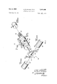
- FIGURE 2 is an isometric pictorial representation of means included in the present invention for providing test signals in a predetermined sequence.
- a flight control system such as an automatic pilot or flight director, may include a monitor having comparators, such as the comparators 1, 2 Vand 3 shown in FIG- URE l. These comparators receive signals e1, e2 and e3 from a functional section 4 of the flight control system, and compare these signals to signals e1', e2 and e3 received from a monitor section 6. .Under normal conditions, the signals received from functional section 4 are balanced by the signals received from monitor section 6, and no error output is provided by comparators 1, 2 and 3. This condition indicates that the iight control system is functioning properly. When a malfunction occurs, this balance is disturbed causing an error signal to be provided by the associated comparators 1, 2 or 3 which is applied to an OR GATE 34 and which actuates an alarm system indicating the malfunction to the pilot.
- comparators 1, 2 Vand 3 shown in FIG- URE l.
- Comparators 1, 2 and 3 may be of the kind disclosed and claimed broadly in co-pending U.S. application Ser. No. 318,050, tiled Oct. 22, 1963, and in co-pending U.S. application Ser. No. 351,426, namelyd Mar. 12, 1964, both tiled by Frank lohn Thomas and Robert Leo Worthington, and assigned to The Bendix Corporation, assignee of the present invention.
- the self-test device constructed according to the present invention simulates a malfunction by introducing a test signal, such as the signal V1, V2 or V3, to deliberately unbalance the signals from functional section 4 and monitor section 6. These test signals are combined with signals e1, e2 and e3 of functional section 4. The combined signals are not balanced by signals e1', e2 and e3 from monitor section 6, and error signals E1, E2 and E3 appear at the output of comparators ⁇ 1, 2 and 3, respectively, to be utilized to apply the test signals to the monitor in a predetermined sequence.
- a test signal such as the signal V1, V2 or V3
- Power from direct current source 8 is directed through relay 10 and a test switch 14 to a flight control system engage circuit 16, which provides for control of the aircraft by an automatic pilot or tiight director system.
- test switch 14 in test position, ldisengages flight control system engage circuit 16, and energizes test solenoid 24.
- Test switch 18, in test position deenergizes a re-set solenoid 26 having a purpose to be hereinafter described.
- a suitable power supply such as a direct current source 32
- input signal v is transmitted to functional section 4 as test signal v1 and combined with the normal output of functional section 4 to provide signal el.
- Signal e1 is compared, by comparator 1, to signal e1 received from monitor section 6. Since the signals are not of equal amplitude, error signal E1 appears at the output of comparator 1, and a malfunction is thus simulated.
- Error signal El is directed through an OR GATE 34, and operates solenoid 12 to move relay 10 to position B shown in FIGURE 1. Heal solenoid is energized to actuate mechanism which indexes rotary switch 28 to position H1.
- test switches 14 and 18 are manually moved by the pilot to their normal positions. Reset solenoid 26 is then energized through test switch 14 and returns rotary switch 28 to its pre-test position.
- indexing mechanism 30 may consist of a ratchet wheel 38 and pawls 40 and 41.
- Ratchet wheel 38 is coupled to rotary switch 28 through shaft 42.
- Rotary switch 28 includes the axially spaced rings 44, 46 and 48, having circumferentially spaced conductive surfaces, such as surfaces T1, T2 and T2, and nonconductive surfaces, such as surfaces H1 and H2.
- the contacts 50, 52 and 54 are suitably supported so as to make contact with rings 44, 46 and 48, respectively.
- Test solenoid 24 and heal solenoid 25 actuate pawls 40 and 41, respectively, so as to advance ratchet wheel 38, and rotary switch 28 coupled thereto, in a particular direction.
- test solenoid 24 coupled to pawl 40 by suitable mechanical means 56, actuates pawl 40 to advance ratchet wheel 38 one step so as to position conductive area T1 of ring 44 under contact 50, causing signal v1 to be applied to functional section 4 as shown in FIGURE l.
- An in ight test will be initiated by the pilot during the iiight of the aircraft to check the integrity of selected circuitry. Particular emphasis, for example, may be placed on testing the circuits required for approach and landing. This will include tests of circuits in the roll and pitch control channels and are coupler monitors. These tests may be performed in a predetermined sequence by using a device constructed according to the present invention as described herein.
- the pilot manually moves test switches 14 and 18 from normal position to test position, with switch 10 in position A, as shown in FIGURE l.
- the desired tests are performed in a predetermined sequence as provided by rotary switch 28.
- Rotary switch 28 applies test signals V1, V2 and V3 to functional section 4 of the ight control system to simulate a malfunction, and comparators 1, 2 or 3 respond thereto to provide error signals El, E2 or E3.
- An error signal so provided energizes relay 12 to move switch 10 to position B, causing rotary switch 28 to be indexed to a position where no test signal is applied. Under these conditions, no error signal will appear at the output of comparators 1, 2 or 3, and switch 10 will move to position A to cause rotary switch 28 to be indexed to a position where test signals are again applied.
- test sequence will be interrupted, since no signal is provided to move switch 10 from position A to position B.
- the test sequence will not continue until the pilot acknowledges the malfunction.
- a successful test is completed when rotary switch 28 is indexed to its last position by indexing mechanism 30, thus signifying removal of the last test signal in the absence of any faults in the system.
- the pilot may then disengage the testing device by manually moving test switches 14 and 18 from test normal positions.
- a device constructed according to the present invention satisfies these requirements and provides adequate assurance that the various components in a flight control system are functioning properly. These tests may be performed in flight at periodic intervals to provide an integrity check or, in the case of a flare computer, may be performed at some time prior to actual use, to provide a functional check.
- the feature provided by the present invention for interrupting a test sequence in case of a malfunction provides a fail safe indication of circuitry error.
- Such a device is an important addition to the automatic control of an aircraft, and should find wide use when automatic pilot or flight director systems are employed.
- test signals V1, V2 and V3 are shown in FIGURE 1, it should be noted that the device is applicable to as many test signals as there are tests to be performed, with each successive test signal causing operation of the device in the manner described. Also, the test signals can be combined with signals el', e2 and e3 from monitor section 4 to create the required unbalance.
- a monitor for a control system comprising:
- rst means for providing a plurality of signals corresponding to a plurality of conditions related to the control system
- sequential switch means connected to the third means and to one of the first and second means for combining the signal from the third means with a selected signal from the one means so that said one means provides signals which do not correspond to the de sired level of the signals from the other of the tirs! and second means;
- comparator means connected to the iirst and second means for providing error signals when the signals from the iirst and second means do not correspond;
- sequential switch control means connected to the cornparator means and to the sequential switch means and responsive to the error signal for sequencing the sequential switch means so that the signal from the third means is combined with the selected signal from the one means in a predetermined sequence, with a system failure being indicated when the sequence is interrupted.
- the sequential switch means is connected to the third means and to the irst means for combining the signal from the third means with a selected signal from the tirst means so that the iirst means provides signals which do not correspond to the desired level of the condition signals.
- the sequential switch means is connected to the third means and to the second means for combining the signal from the third means with a selected signal from the second means so that the second means provides signals which do not correspond to the desired level of the condition signals.
- the sequential switch means is a rotary switch having conductive and non-conductive areas
- the sequential switch control means is responsive to the error signal for rotating the rotary switch whereupon the conductive and non-conducting areas are positioned to combine the signal from the third means with the selected signal from the one means in the predetermined sequence.
- a monitor as described in claim 4, wherein the se quential switch control means comprises:
- a switch connected to the comparator means and responsive to the error signals therefrom for sequentially connecting the power supply to the first and second solenoids for energizing said solenoids to actuate the sequencing mechanism and to rotate the switch.
- the sequencing mechanism is actuated for rotating the switch and for positioning the conductive areas of the switch to combine the signal from the third means with the selected signal from the one means when the first solenoid is energized;
- said sequencing mechanism is actuated for rotating the switch and for positioning the non-conductive areas of the switch to prevent combining of the signal from the third means with the selected signal from the one means when the second solenoid is energized.
- the comparator means provides the error signals when the rotary switch is positioned for combining the signal from the third means with the selected signa] from the one means.
- a monitor as described by claim 1, wherein the comparator means connected to the iirst and second means for providing error signals when the signals from the first and second means do not correspond comprises:
- gating means connected to all of the comparators for providing the error signals when at least one of the comparators provides a di'erence signal.
Landscapes
- Engineering & Computer Science (AREA)
- Physics & Mathematics (AREA)
- General Physics & Mathematics (AREA)
- General Engineering & Computer Science (AREA)
- Aviation & Aerospace Engineering (AREA)
- Microelectronics & Electronic Packaging (AREA)
- Computer Hardware Design (AREA)
- Radar, Positioning & Navigation (AREA)
- Remote Sensing (AREA)
- Automation & Control Theory (AREA)
- Testing And Monitoring For Control Systems (AREA)
- Testing Of Balance (AREA)
- Testing Or Calibration Of Command Recording Devices (AREA)
- Testing Electric Properties And Detecting Electric Faults (AREA)
Applications Claiming Priority (1)
| Application Number | Priority Date | Filing Date | Title |
|---|---|---|---|
| US48237065A | 1965-08-25 | 1965-08-25 |
Publications (1)
| Publication Number | Publication Date |
|---|---|
| US3448449A true US3448449A (en) | 1969-06-03 |
Family
ID=23915780
Family Applications (1)
| Application Number | Title | Priority Date | Filing Date |
|---|---|---|---|
| US482370A Expired - Lifetime US3448449A (en) | 1965-08-25 | 1965-08-25 | Automatic test device |
Country Status (3)
| Country | Link |
|---|---|
| US (1) | US3448449A (enExample) |
| JP (1) | JPS5327558B1 (enExample) |
| DE (1) | DE1488877B2 (enExample) |
Cited By (3)
| Publication number | Priority date | Publication date | Assignee | Title |
|---|---|---|---|---|
| US3573772A (en) * | 1968-07-05 | 1971-04-06 | Gen Electric | Condition responsive indicating instrument |
| FR2417895A1 (fr) * | 1978-02-17 | 1979-09-14 | Hasler Ag | Dispositif pour emettre sans erreurs plusieurs signaux de sortie en fonction d'une grandeur electrique variable |
| US4710750A (en) * | 1986-08-05 | 1987-12-01 | C & K Systems, Inc. | Fault detecting intrusion detection device |
Citations (8)
| Publication number | Priority date | Publication date | Assignee | Title |
|---|---|---|---|---|
| US2696604A (en) * | 1952-08-02 | 1954-12-07 | Bailey Meter Co | Supervisory system |
| US2732544A (en) * | 1956-01-24 | Tfxstmr mfaintcfor alv intruder | ||
| US2815500A (en) * | 1955-12-14 | 1957-12-03 | Leeds And Northrop Company | Monitoring system for continuously selecting extreme variables |
| US3082412A (en) * | 1959-04-07 | 1963-03-19 | Isi Inc | Variable monitoring system |
| US3159747A (en) * | 1960-01-12 | 1964-12-01 | Nuclear Materials & Equipment | Fail proof radiation monitor and alarm circuit |
| US3178695A (en) * | 1960-06-28 | 1965-04-13 | Westinghouse Electric Corp | Indicating apparatus |
| US3189883A (en) * | 1961-12-18 | 1965-06-15 | Sylvania Electric Prod | Test and reset circuit for intrusion alarm system |
| US3202976A (en) * | 1959-12-03 | 1965-08-24 | Scully Signal Co | Supervisory system with failure discrimination |
-
1965
- 1965-08-25 US US482370A patent/US3448449A/en not_active Expired - Lifetime
-
1966
- 1966-08-15 JP JP5329266A patent/JPS5327558B1/ja active Pending
- 1966-08-23 DE DE19661488877 patent/DE1488877B2/de active Pending
Patent Citations (8)
| Publication number | Priority date | Publication date | Assignee | Title |
|---|---|---|---|---|
| US2732544A (en) * | 1956-01-24 | Tfxstmr mfaintcfor alv intruder | ||
| US2696604A (en) * | 1952-08-02 | 1954-12-07 | Bailey Meter Co | Supervisory system |
| US2815500A (en) * | 1955-12-14 | 1957-12-03 | Leeds And Northrop Company | Monitoring system for continuously selecting extreme variables |
| US3082412A (en) * | 1959-04-07 | 1963-03-19 | Isi Inc | Variable monitoring system |
| US3202976A (en) * | 1959-12-03 | 1965-08-24 | Scully Signal Co | Supervisory system with failure discrimination |
| US3159747A (en) * | 1960-01-12 | 1964-12-01 | Nuclear Materials & Equipment | Fail proof radiation monitor and alarm circuit |
| US3178695A (en) * | 1960-06-28 | 1965-04-13 | Westinghouse Electric Corp | Indicating apparatus |
| US3189883A (en) * | 1961-12-18 | 1965-06-15 | Sylvania Electric Prod | Test and reset circuit for intrusion alarm system |
Cited By (4)
| Publication number | Priority date | Publication date | Assignee | Title |
|---|---|---|---|---|
| US3573772A (en) * | 1968-07-05 | 1971-04-06 | Gen Electric | Condition responsive indicating instrument |
| FR2417895A1 (fr) * | 1978-02-17 | 1979-09-14 | Hasler Ag | Dispositif pour emettre sans erreurs plusieurs signaux de sortie en fonction d'une grandeur electrique variable |
| US4710750A (en) * | 1986-08-05 | 1987-12-01 | C & K Systems, Inc. | Fault detecting intrusion detection device |
| USRE33824E (en) * | 1986-08-05 | 1992-02-18 | Fault detecting intrusion detection device |
Also Published As
| Publication number | Publication date |
|---|---|
| DE1488877B2 (de) | 1971-09-09 |
| DE1488877A1 (de) | 1969-07-03 |
| JPS5327558B1 (enExample) | 1978-08-09 |
Similar Documents
| Publication | Publication Date | Title |
|---|---|---|
| US11603213B2 (en) | System and method for auto-execution of aircraft check lists | |
| US4825151A (en) | Weapon interface system evaluator | |
| US3813647A (en) | Apparatus and method for performing on line-monitoring and fault-isolation | |
| US20180113796A1 (en) | Automatic generation of data coupling and control coupling test conditions | |
| US7801702B2 (en) | Enhanced diagnostic fault detection and isolation | |
| US4039813A (en) | Apparatus and method for diagnosing digital data devices | |
| US3541550A (en) | Warning device | |
| US3448449A (en) | Automatic test device | |
| US20050223288A1 (en) | Diagnostic fault detection and isolation | |
| US2945915A (en) | Operational checkout of data handling equipment | |
| US3237157A (en) | Apparatus for detecting and localizing malfunctions in electronic devices | |
| US3289193A (en) | Monitoring system for redundant systems | |
| US4001554A (en) | Mode control computer interface | |
| US3401549A (en) | Failure monitor for attitude reference systems | |
| US3735255A (en) | Apparatus and method for testing a multi-terminal logic circuit capable of detecting fixed and intermittant faults | |
| CN115903737B (zh) | 一种二乘二取二计算机自动化测试系统及方法 | |
| CN112363481B (zh) | 一种电传飞控系统的航后自检测控制装置和控制方法 | |
| US3573445A (en) | Device for programmed check of digital computers | |
| KR101584717B1 (ko) | 항공기용 임베디드 시스템 탑재 소프트웨어 고장 처리 모듈 시험 방법 및 장치 | |
| RU2459224C1 (ru) | Устройство ввода дискретных сигналов в резервированную систему управления для стендовых испытаний ракетно-космической техники | |
| Doig | Test Equipment for Rapid Automatic Check‐out and Evaluation: An account of an automatic testing rig for aircraft systems now in use by major airlines | |
| US3619584A (en) | Computer problem setup testing system | |
| Tuttle et al. | Built-in-Test and External Tester Reliability Characteristics. | |
| Sarla et al. | Automation of Combinatorial Interaction Test (CIT) Case Generation and Execution for Requirements based Testing (RBT) of Complex Avionics Systems | |
| Funderburk | Automation in Saturn I First Stage Checkout |