US3441234A - Reeling-off apparatus for use in connection with one-way rolling mills - Google Patents
Reeling-off apparatus for use in connection with one-way rolling mills Download PDFInfo
- Publication number
- US3441234A US3441234A US473394A US3441234DA US3441234A US 3441234 A US3441234 A US 3441234A US 473394 A US473394 A US 473394A US 3441234D A US3441234D A US 3441234DA US 3441234 A US3441234 A US 3441234A
- Authority
- US
- United States
- Prior art keywords
- coil
- turntable
- stand
- rolling stand
- remote
- Prior art date
- Legal status (The legal status is an assumption and is not a legal conclusion. Google has not performed a legal analysis and makes no representation as to the accuracy of the status listed.)
- Expired - Lifetime
Links
Images


Classifications
-
- B—PERFORMING OPERATIONS; TRANSPORTING
- B21—MECHANICAL METAL-WORKING WITHOUT ESSENTIALLY REMOVING MATERIAL; PUNCHING METAL
- B21C—MANUFACTURE OF METAL SHEETS, WIRE, RODS, TUBES, PROFILES OR LIKE SEMI-MANUFACTURED PRODUCTS OTHERWISE THAN BY ROLLING; AUXILIARY OPERATIONS USED IN CONNECTION WITH METAL-WORKING WITHOUT ESSENTIALLY REMOVING MATERIAL
- B21C47/00—Winding-up, coiling or winding-off metal wire, metal band or other flexible metal material characterised by features relevant to metal processing only
- B21C47/34—Feeding or guiding devices not specially adapted to a particular type of apparatus
-
- B—PERFORMING OPERATIONS; TRANSPORTING
- B21—MECHANICAL METAL-WORKING WITHOUT ESSENTIALLY REMOVING MATERIAL; PUNCHING METAL
- B21C—MANUFACTURE OF METAL SHEETS, WIRE, RODS, TUBES, PROFILES OR LIKE SEMI-MANUFACTURED PRODUCTS OTHERWISE THAN BY ROLLING; AUXILIARY OPERATIONS USED IN CONNECTION WITH METAL-WORKING WITHOUT ESSENTIALLY REMOVING MATERIAL
- B21C47/00—Winding-up, coiling or winding-off metal wire, metal band or other flexible metal material characterised by features relevant to metal processing only
- B21C47/24—Transferring coils to or from winding apparatus or to or from operative position therein; Preventing uncoiling during transfer
- B21C47/245—Devices for the replacement of full reels by empty reels or vice versa, without considerable loss of time
Definitions
- the present invention relates to a reeling-off apparatus on one-way rolling mills for coreless coils and also for coils with a core formed by a reel, in which a turntable with two coil carriers located symmetrically thereon with regard to the center of said turntable is arranged ahead of the rolling stand.
- Reeling-off apparatuses with a turntable ahead of the one-way rolling mill are known, in which the turntable has mounted thereon two symmetrically arranged coil carriers while the respective coil carrier which is remote from the rolling stand serves to receive and wind up material received fro another coil carrier which is arranged behind the turntable.
- the terms ahad of, behind and adjacent are meant with regard to the feeding direction of the material toward the rolling stand.
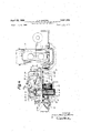
- FIG. 1 is a side view partially in section of an arrangement according to the present invention.
- FIG. 2 is a top view of the device shown in FIG. 1.
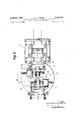
- FIG. 3 is a section one line IIIIII of FIG. 2.
- FIGS. 4 and 5 are side and plan views respectively, of a modification showing improvements in the journaling and drive of the turntable and also showing a cradle pertaining to one station of the turntable which is supported independently of the turntable.
- the present invention which, as mentioned above, refers to a reeling-off apparatus on one-way rolling mills for coils with and without cores in which a turntable with two symmetrically arranged coil carriers is located ahead of the rolling stand, is characterized in that in longitudinal direction of the coil carriers adjacent the turntable there is provided an arm which is movable as to height, and which is also transversely movable and swingable, and which is provided with removing means for removing a coil thereon. Further, a braking device is provided for that coil carrier adjacent the rolling stand which is adapted to be coupled with the shaft of the re spective coil carrier in front of the rolling stand to control the said carrier.
- the coil to be supplied to the rolling stand is received by the said transversely movable arm and together therewith is so tilted and moved laterally and in upward direction that the said arm will move to the level and into the direct vicinity of the expansion shaft of that coil carrier which is remote from the rolling stand.
- the coil is opened and the start of the coil is trimmed by shears.
- each coil carrier is provided with removing means which simultaneously serves as counter hearing. It will be appreciated that in this Way, regardless of the width of the coil, the coil will always be placed into the desired position with regard to the longitudinal axis of the rolling stand.
- This removing means is also em ployed for removing empty reels from the expansion shaft and moving the same onto the transversely movable arm, if the operation is carried out with coils having a core.
- Each coil carrier preferably comprises a coil support adapted to be raised and lowered and equipped with driven members.
- each coil carrier has a coil opener.
- the drive of the coil support as well as of the transporting pair of rollers associated with each coil carrier is mounted on said turntable.
- a straightening or levelling path may be provided or one or more adjustable bending rollers.
- the arrangement shown therein comprises a rolling stand 1 and a turntable 2 which when looking in the feeding direction indicated by the arrow A (FIG. 2) is located in front of rolling stand 1.
- a turntable 2 which when looking in the feeding direction indicated by the arrow A (FIG. 2) is located in front of rolling stand 1.
- Mounted on turntable 2 and arranged symmetrically with regard to its center point M are two coil carriers 3 and 4.
- Each coil carrier 3, 4 has an expansion shaft 5, a coil opener 6 and a coil support 7 which is adapted to be moved upwardly and downwardly in the direction and opposite to the direction of the arrow C.
- Each coil carrier 3, 4 also comprises driven rollers 8 and pivotally journalled transporting rollers 9 which, similar to rollers 8, may be driven by driving means on turntable 2.
- Each expansion shaft 5 has associated therewith removing means 10 which simultaneously serves as abutment for the coil placed upon the expansion shaft 5 in order to align the transverse central portion of the coil with the longitudinal central portion of rolling stand 1.
- Each expansion shaft 5 has an extension 11 which through gears or the like is operatively connected with a stub shaft 12.
- Stub shaft 12 is adapted to be coupled to shaft 14 of a brake generator while the coil carrier occupies a position adjacent rolling stand 1.
- This brake generator is in longitudinal direction of that coil carrier which is adjacent the rolling stand 1 arranged stationarily adjacent the turntable 2.
- the brake generator comprises transmission gear 15 having the aforementioned shaft 14 and also having connected thereto a brake motor 25.
- Member 12a on shaft 12 and 13 on shaft 14 etl'ect detachable driving connection of shaft 12 to shaft 14.
- Member 12a may be a splined end on shaft 12 while member 13 may be a splined sleeve reciprocable on shaft 14.
- shears 16 are provided behind turntable 2 and thus adjacent the respective coil carrier 3 which is remote from the rolling stand 1, there are provided shears 16 in the form of roller shears. These shears are arranged stationarily and if desired may be replaced by a sheet sheers or plate shears.
- a guiding member 17 on which a rotatable frame part 18 is movable in the direction of the arrow D.
- a supporting member 19 which is adjustable as to height and carries a transversely movable arm 20.
- Supporting member 19 is provided with removing means comprising a piston and cylinder 21a and a pusher plate 21.
- arm 20 can be aligned with expansion shaft 5 of the respective coil carrier which is remote from the rolling stand 1 so that coil W on arm 20 can by means of pusher plate 21 be moved onto expansion shaft 5 of said last mentioned coil carrier.
- FIG. 3 shows more in detail the construction of the turntable and the parts thereon.
- turntable 2 has gear teeth or the like at 2a by means of which the turntable can be driven in rotation by suitable motor means (not shown )while support means 2b support and guide the turntable.
- Arresting means serve to locate the turntable in its two indexed positions. If the turntable indexes reversibly from one position to the other, simple abutment means will provide for the two turntable locations while if the turntable always indexes in one direction, arresting means 311 would include a retractible abutment element.
- FIGURE 3 also shows that shaft 5 has a radially movable portion 5b which can be pushed outwardly to engage the hole in a coil by movement of portion 5b along the cam-like member 5c in shaft 5, by the piston 5a connected to portion 511 by rod 5d. Spring means (not shown) could be employed to retract portion 5b.
- rollers 9 may be carried by arm means on a shaft 9a which is rotatable by motor 9b to press rollers 9 against the coil or to retract them from the coil.
- rollers 8 are connected with the drive motor 7b therefor by chain means 70. Rollers 8 and motor 7b are mounted in a carriage 7d which is vertically movable in frame 7e which is fixed to turntable 2. Fluid motor means 7a connected between frame 7e and carriage 7d is operable for effecting the said vertical movement of the carriage.
- FIG. 3 also shows that shaft 5 carries gear means 5 which mesh with pinion means 12b on shaft 12 so shaft 5 can be placed under the control of the braking mechanism.
- FIG. 3 further shows that the removing means comprises piston and cylinder means 33a and a pusher plate 33 on the piston.
- the pusher plate 33 can be positioned, as previously mentioned, by piston and cylinder means 33a so as to stop a coil placed on shaft 5 in the proper longitudinal position on the shaft.
- support arm 20 which picks up new coils and places them on the turntable, is carried by a sleeve 31 that is vertically movable on a column 30 as indicated by the arrow F by a fluid motor 32.
- Column 30 is mounted on rotary base member 28 which has peripheral teeth engaged by a pinion 27 that is driven by a motor 29.
- Member 28 is rotatable about a pivot 26 and when motor 29 is energized, the member 28 and all parts supported thereon rotate as indicated by the arrow G.
- the entire assembly is slidable on stationary support means 32a so as to take the motion indicated by arrow D.
- expansion shaft 5 of the coil carrier 3 which is remote from rolling stand 1 may be loaded with a new coil and the preparations therefor may be carried out, such as straightening, clamping and opening of the coil, the advance of the coil start and the trimming thereof.
- turntable 2 is rotated by after the rotatable frame part 18 has been moved back into its dot-dash line position. In this instance, it receives a new coil, whereas stub shaft 12 of coil carrier newly moved into the position adjacent rolling stand 1, is coupled with counter shaft 14 of the transmission by means of member 12a, 13.
- Each coil carrier may, as illustrated, comprise a straightening path including a plurality of rollers 22 or may have one or more adjustable bending rollers in addition to the transporting roller 9.
- a turntable 42 is rotatably supported adjacent a rolling stand 41.
- the material feeds from the turntable to the rolling stand in the direction of arrow E.
- the turntable has coil supports 43, 44 symmetrically arranged with respect to center M of the turntable.
- Turntable 42 is giuded by the king journal 45 and is additionally jornalled on rollers 46 along its marginal portion.
- the drive of the turntable may be effected by a gear ring 42a on the bottom of the turntable which is engaged by pinion 47 driven by a motor 48.
- the arrangement may be such that hook-shaped or similar arresting means 49 may be adapted to engage predetermined regions of the marginal portion of the turntable.
- Arresting mans 49 of which there are two, are hydraulically actuated by pistons arranged in cylinders 50 and are adapted to be brought into engagement with and out of engagement with said turntable to lock and release the turntable.
- Turntable 42 carries one stationary bearing means 51, 52 each for each of the two coil supports 43, 44 while means may be provided for coupling that coil support which is located at the rolling stand to a brake means 53 arranged adjacent turntable 42 for purposes of producing a braking force on the coil.
- the end of each coil support opposite the stationary "bearing therefor is held by an arm 54 adapted to be tilted in outward direction to expose the end of the coil.
- Each coil support has, in addition to a coil opener associated therewith, rollers 55, '56 journalled in a frame 56a which is tiltable on tilting arm 57 which is capable of adapting itself to the changing size of the coil.
- Turntable 42 is, underneath each coil support 43, 44, provided with a passage 58, 59.
- a stationary box 60 in which there is guided a second box 61.
- This second box is under the influence of fluid motor 62 which is adapted to move a station or carriage 63 arranged in the upper portion of the second box 61 upwardly and downwardly, i.e. into the positions 63' and 63" and vice versa.
- carriage 63 may be movedin upward direction during which movement it may pass through passages 58 or 59, respectively.
- the carriage 63 includes driven rollers 63a which are connected to a drive motor 63b. Rollers 63a thus perform the function of rollers 8 of the first modification and can, for instance supply power to draw in a web of metal and coil it up in station 43 preparatory to movement of the coil into position adjacent the rolling stand. These rollers also can drive a coil placed in station 43 during opening of the coil.
- the turntable according to the present invention with the parts arranged thereon is, due to the arrangement of station 63 which is independent of the turntable, lighter than heretofore known embodiments.
- the turntable is provided with inclined marginal portions 64 arranged at recesses along the circumference of the turntable while the rolling stand is provided with corresponding small blocks 65 which, by means of fluid motor means 66, are movable along a guiding means 67 in upward and downward direction in such a way that each small block 65 is adapted to be moved from the position indicated in FIG. 4 in solid lines into position 65 indicated in dot-dash lines, and vice versa.
- each block is brought in its disengaged position indicated at 65'.
- the turntable is, in the vicinity of blocks 65, pressed onto the corresponding roller support 46a.
- the two cylinders 50 together with the arresting or clamp means 49 perform a corresponding bracing of the turntable against the supporting rollers 46 connected to the foundation.
- FIGS. 4 and 5 The operation of the modification of FIGS. 4 and 5 is the same as described above for FIGS. 1-3 except for the carriage 63 in FIGS. 4 and 5 having the rollers 63a which is stationary instead of being movable with the turntable as in the case of the modification of FIGS. 1-3.
- an apparatus for reeling off coils to be fed into said rolling stand comprising: a turntable arranged ahead of said rolling stand when looking in the direction in which coils are fed into said rolling stand, two coil supports each being adapted to receive a coil, said coil supports being arranged on said turntable on opposite sides of the axis of rotation thereof and symmetrically with regard to said axis, the arrangement being such that when one of said coil supports is adjacent said rolling stand the other one of said coilsupports is remote from said stand, each of said coil supports having a rotatable shaft operable to support the respective coil, and supporting means arranged adjacent that coil support which is remote from said stand for receiving a coil and transferring the same to the respective adjacent coil support.
- each of said coil supports includes an expendable substantially cylindrical member adapted to receive a coil and equipped with stripper means for a coil and also serving as an abutment therefor.
- each coil support includes means for engaging the coil thereon from beneath to rotate the coil and is also provided with coil opening means.
- an apparatus for reeling ofii coils to be fed into said rolling stand comprising: a turntable arranged ahead of said rolling stand when looking in the direction in which coils are fed into said rolling stand, two coil supports each being adapted to receive a coil, said coil supports being arranged on said turntable on opposite sides of the axis of rotation thereof and symmetrically with regard to said axis, the arrangement being such that when one of said coil supports is adjacent said rolling stand the other one of said coil supports is remote from said stand, two pairs of transport rollers respectively associated with said coil supports and drivingly connected to said turntable, and supporting means arranged adjacent that coil support which is remote from said stand for receiving a coil and transferring the same to the respective adjacent coil support.
- a turntable rotatably mounted on a vertical axis at the entrance side of said stand, a pair of coil supports on said turntable symmetrically positioned thereon on opposite sides of the axis of rotation of the turntable, said turntable being indexable to position either one of said coil supports adjacent said stand while the other is remote from said stand, said turntable having an opening therein under each coil support, and a station positioned beneath the turntable and under the opening of the said other coil support which is remote from the stand and including a carriage vertically reciprocable through the said opening and having driven roller means at the upper end thereof to engage beneath a coil in the said coil support remote from the stand.
- a turntable rotatably mounted on a vertical axis at the entrance side of said stand, a pair of coil supports on said turntable symmetrically positioned thereon on opposite sides of the axis of rotation of the turntable, said turntable being indexable to position either one of said coil supports adja cent said stand while the other is remote from said stand, said turntable having an opening therein under each coil support, and a station positioned beneath the turntable and under the opening of the said other coil support which is remote from the stand and including a carriage vertically reciprocable through the said opening and having driven roller means at the upper end thereof to engage beneath a coil in the said coil support remote from the stand, said station also including a stationarily mounted frame, and means in the frame slidably engaging said carriage for guiding it in its said reciprocal movement.
- a turntable rotatably mounted on a vertical axis at the entrance side of said stand, a pair of coil supports on said turntable symmetrically positioned thereon on opposite sides of the axis of rotation of the turntable, said turntable being indexable to position either one of said coil supports adjacent said stand while the other is remote from said stand, said turntable having an opening therein under each coil support, and a station positioned beneath the turntable and under the opening of the said other coil support which is remote from the stand and including a carriage vertically reciprocable through the said opening and having driven roller means at the upper end thereof to engage beneath a coil in the said coil support remote from the stand, and clamp means stationarily mounted adjacent the periphery of said turntable operable to engage said turntable in the indexed positions thereof and to clamp and hold said turntable fixed relative to said stand.
- said clamp means includes vertically reciprocable wedge block means on the side of said turntable adjacent said stand, and said turntable having inclined regions on the periphery thereof which register with said wedge block means in the indexed positions of said turntable and which are engageable by said wedge block means upon reciprocation thereof.
- said clamp means comprises further clamp elements located on the side of said turntable remote from said stand, said further clamp elements also being engageable with the turntable in clamping holding relation thereto in the indexed positions of said turntable.
Landscapes
- Engineering & Computer Science (AREA)
- Mechanical Engineering (AREA)
- Winding, Rewinding, Material Storage Devices (AREA)
Description
April 29, I E. H.BARTEN I H 3,441,234
REELING-OFF APPARATUS FOR USE 'IN CONNECTION WITH ONE-WAY ROLLING MILLS I Filed July 20, 1965 Sheet of 4 INVENTOR. 772.17 Mvwr/V B ar/e 0 Apnl 29, 1969 E. H. BARTEN 3,441,234
REELING-OFF APPARATUS FOR USE IN CONNECTION WITH ONE-WAY ROLLING MILLS I Filed July 20, 1965 Sheet 2 'of 4 Q Q N \l INVEN'TQR.
511/ (ye/017% a ar/6 n Apnl 29, 1969 E. H. BARTEN 3,441,234
REELING-OFF APPARATUS FOR USE IN CONNECTION WITH ONE-WAY ROLLING MILLS Filed July 20, 1965 Sheet 3 of 4 INVENTOR. A r/2.0 flvarr? Bar/(a 7 BY W April 29, 1969 E. H. BARTEN 3,441,234
REELING-OFF APPARATUS FOR USE IN CONNECTION WITH ONE-WAY ROLLING MILLS Filed July 20, 1965 Sheet '4 054 I l l I r l a 9 I y l INVENTOR.
BY g
United States Patent Office 3,441,234 Patented Apr. 29, 1969 3,441,234 REELING-OFFAPPARATUS FOR USE IN CONNEC- TION WITH ONE-WAY ROLLING MILLS Ernst Heinrich Barten, Buschhutten, Germany, assignor to Achenbach Sohne G.m.b.H., Siegen, Germany Filed July 20, 1965, Ser. No. 473,394 Int. Cl. B21c 1/00 US. Cl. 242-80 11 Claims The present invention relates to a reeling-off apparatus on one-way rolling mills for coreless coils and also for coils with a core formed by a reel, in which a turntable with two coil carriers located symmetrically thereon with regard to the center of said turntable is arranged ahead of the rolling stand.
Reeling-off apparatuses with a turntable ahead of the one-way rolling mill are known, in which the turntable has mounted thereon two symmetrically arranged coil carriers while the respective coil carrier which is remote from the rolling stand serves to receive and wind up material received fro another coil carrier which is arranged behind the turntable. The terms ahad of, behind and adjacent are meant with regard to the feeding direction of the material toward the rolling stand.
The heretofore known reeling off devices of the general type mentioned above require a special drive for the rewinding operation in addition to the customary withdrawing means.
It is, therefore, an object of the present invention to provide an improved and simplified reeling-off apparatus for rolling mills.
It is another object of this invention to provide a reeling-off apparatus for rolling mills, which will not re quire an additional drive for the rewinding of the coil nor additional withdrawing means behind the turntable.
These and other objects and advantages of the invention will appear more clearly from the following specification in connection with the accompanying drawing, in which:
FIG. 1 is a side view partially in section of an arrangement according to the present invention.
FIG. 2 is a top view of the device shown in FIG. 1.
FIG. 3 is a section one line IIIIII of FIG. 2.
FIGS. 4 and 5 are side and plan views respectively, of a modification showing improvements in the journaling and drive of the turntable and also showing a cradle pertaining to one station of the turntable which is supported independently of the turntable.
The present invention which, as mentioned above, refers to a reeling-off apparatus on one-way rolling mills for coils with and without cores in which a turntable with two symmetrically arranged coil carriers is located ahead of the rolling stand, is characterized in that in longitudinal direction of the coil carriers adjacent the turntable there is provided an arm which is movable as to height, and which is also transversely movable and swingable, and which is provided with removing means for removing a coil thereon. Further, a braking device is provided for that coil carrier adjacent the rolling stand which is adapted to be coupled with the shaft of the re spective coil carrier in front of the rolling stand to control the said carrier.
The coil to be supplied to the rolling stand is received by the said transversely movable arm and together therewith is so tilted and moved laterally and in upward direction that the said arm will move to the level and into the direct vicinity of the expansion shaft of that coil carrier which is remote from the rolling stand. When the coil has been placed onto the expansion shaft of said coil carrier, the coil is opened and the start of the coil is trimmed by shears.
In order to assure that the coil to be placed upon the expansion shaft of that respective coil carrier which is remote from the rolling stand will adopt the desired position with regard to the longitudinal direction of the rollin gstand, each coil carrier is provided with removing means which simultaneously serves as counter hearing. It will be appreciated that in this Way, regardless of the width of the coil, the coil will always be placed into the desired position with regard to the longitudinal axis of the rolling stand. This removing means is also em ployed for removing empty reels from the expansion shaft and moving the same onto the transversely movable arm, if the operation is carried out with coils having a core.
Each coil carrier preferably comprises a coil support adapted to be raised and lowered and equipped with driven members. In addition thereto, each coil carrier has a coil opener. The drive of the coil support as well as of the transporting pair of rollers associated with each coil carrier is mounted on said turntable. In addition to the transporting rollers, depending on the thickness of the coil, a straightening or levelling path may be provided or one or more adjustable bending rollers.
Referring now to the drawing in detail, the arrangement shown therein comprises a rolling stand 1 and a turntable 2 which when looking in the feeding direction indicated by the arrow A (FIG. 2) is located in front of rolling stand 1. Mounted on turntable 2 and arranged symmetrically with regard to its center point M are two coil carriers 3 and 4. When turning turntable 2 by in the direction of the arrow B or in opposite direction, always one coil carrier can be located directly in front of rolling stand 1, Whereas the other coil carrier will be located remote from said rolling stand 1.
Each coil carrier 3, 4 has an expansion shaft 5, a coil opener 6 and a coil support 7 which is adapted to be moved upwardly and downwardly in the direction and opposite to the direction of the arrow C. Each coil carrier 3, 4 also comprises driven rollers 8 and pivotally journalled transporting rollers 9 which, similar to rollers 8, may be driven by driving means on turntable 2. Each expansion shaft 5 has associated therewith removing means 10 which simultaneously serves as abutment for the coil placed upon the expansion shaft 5 in order to align the transverse central portion of the coil with the longitudinal central portion of rolling stand 1.
Each expansion shaft 5 has an extension 11 which through gears or the like is operatively connected with a stub shaft 12. Stub shaft 12 is adapted to be coupled to shaft 14 of a brake generator while the coil carrier occupies a position adjacent rolling stand 1. This brake generator is in longitudinal direction of that coil carrier which is adjacent the rolling stand 1 arranged stationarily adjacent the turntable 2. The brake generator comprises transmission gear 15 having the aforementioned shaft 14 and also having connected thereto a brake motor 25. Member 12a on shaft 12 and 13 on shaft 14 etl'ect detachable driving connection of shaft 12 to shaft 14. Member 12a may be a splined end on shaft 12 while member 13 may be a splined sleeve reciprocable on shaft 14.
Behind turntable 2 and thus adjacent the respective coil carrier 3 which is remote from the rolling stand 1, there are provided shears 16 in the form of roller shears. These shears are arranged stationarily and if desired may be replaced by a sheet sheers or plate shears.
Also arranged adjacent turntable 2 is a guiding member 17 on which a rotatable frame part 18 is movable in the direction of the arrow D. On this rotatable frame part there is pivotally journalled a supporting member 19 which is adjustable as to height and carries a transversely movable arm 20. Supporting member 19 is provided with removing means comprising a piston and cylinder 21a and a pusher plate 21. It will thus be appreciated that arm 20 may from its dot-dash position shown in FIG. 2 be moved into the solid line position thereof and may be turned and adjusted as to height so that it can be aligned with the expansion shaft of the respective coil carrier which is remote from the rolling stand 1. In this way arm 20 can be aligned with expansion shaft 5 of the respective coil carrier which is remote from the rolling stand 1 so that coil W on arm 20 can by means of pusher plate 21 be moved onto expansion shaft 5 of said last mentioned coil carrier. After the coil opener 6 has been actuated and also rollers 8 and 9 have been actuated, the coil start can be trimmed by shears 16.
FIG. 3 shows more in detail the construction of the turntable and the parts thereon. In this view it will be seen that turntable 2 has gear teeth or the like at 2a by means of which the turntable can be driven in rotation by suitable motor means (not shown )while support means 2b support and guide the turntable.
Arresting means, as shown schematically at 3:1, serve to locate the turntable in its two indexed positions. If the turntable indexes reversibly from one position to the other, simple abutment means will provide for the two turntable locations while if the turntable always indexes in one direction, arresting means 311 would include a retractible abutment element. FIGURE 3 also shows that shaft 5 has a radially movable portion 5b which can be pushed outwardly to engage the hole in a coil by movement of portion 5b along the cam-like member 5c in shaft 5, by the piston 5a connected to portion 511 by rod 5d. Spring means (not shown) could be employed to retract portion 5b.
The rollers 9 may be carried by arm means on a shaft 9a which is rotatable by motor 9b to press rollers 9 against the coil or to retract them from the coil.
The rollers 8, are connected with the drive motor 7b therefor by chain means 70. Rollers 8 and motor 7b are mounted in a carriage 7d which is vertically movable in frame 7e which is fixed to turntable 2. Fluid motor means 7a connected between frame 7e and carriage 7d is operable for effecting the said vertical movement of the carriage.
FIG. 3 also shows that shaft 5 carries gear means 5 which mesh with pinion means 12b on shaft 12 so shaft 5 can be placed under the control of the braking mechanism.
FIG. 3 further shows that the removing means comprises piston and cylinder means 33a and a pusher plate 33 on the piston. The pusher plate 33 can be positioned, as previously mentioned, by piston and cylinder means 33a so as to stop a coil placed on shaft 5 in the proper longitudinal position on the shaft.
In FIG. 3 it will be seen that support arm 20, which picks up new coils and places them on the turntable, is carried by a sleeve 31 that is vertically movable on a column 30 as indicated by the arrow F by a fluid motor 32. Column 30 is mounted on rotary base member 28 which has peripheral teeth engaged by a pinion 27 that is driven by a motor 29. Member 28 is rotatable about a pivot 26 and when motor 29 is energized, the member 28 and all parts supported thereon rotate as indicated by the arrow G. The entire assembly is slidable on stationary support means 32a so as to take the motion indicated by arrow D.
In operation, and with reference, in particular, to the modification of FIGS. 1-3, while the coil located on the expansion shaft 5 of that coil carrier 4 which is adjacent stand 1 moves into rolling stand 1, expansion shaft 5 of the coil carrier 3 which is remote from rolling stand 1 may be loaded with a new coil and the preparations therefor may be carried out, such as straightening, clamping and opening of the coil, the advance of the coil start and the trimming thereof. When these preparations concerning the coil on coil carrier 3 and the unrolling of the coil of coil carrier 4 have been completed, turntable 2 is rotated by after the rotatable frame part 18 has been moved back into its dot-dash line position. In this instance, it receives a new coil, whereas stub shaft 12 of coil carrier newly moved into the position adjacent rolling stand 1, is coupled with counter shaft 14 of the transmission by means of member 12a, 13.
Each coil carrier may, as illustrated, comprise a straightening path including a plurality of rollers 22 or may have one or more adjustable bending rollers in addition to the transporting roller 9.
When coils are involved which have a reel as core, the operation is analogous. However, prior to placing a new coil through the intervention of arm 20 onto the respective coil carrier which is to be charged, the empty reel left on the coil carrier previously processed, has to be stipped otf expansion shaft 5 by a stripper 10 onto arm 20 and then has to be removed from the latter by means of the pusher plate.
Referring now to the modification of FIGS. 4 and 5, a turntable 42 is rotatably supported adjacent a rolling stand 41. The material feeds from the turntable to the rolling stand in the direction of arrow E. The turntable has coil supports 43, 44 symmetrically arranged with respect to center M of the turntable.
The carriage 63 includes driven rollers 63a which are connected to a drive motor 63b. Rollers 63a thus perform the function of rollers 8 of the first modification and can, for instance supply power to draw in a web of metal and coil it up in station 43 preparatory to movement of the coil into position adjacent the rolling stand. These rollers also can drive a coil placed in station 43 during opening of the coil.
If it is intended to turn the turntable 42 with coil supports 43, 44, in order to move a coil placed on the coil support remote from rolling stand 41 into the position adjacent the rolling stand, it is necessary to move station 63 downwardly into the box 60.
The turntable according to the present invention with the parts arranged thereon is, due to the arrangement of station 63 which is independent of the turntable, lighter than heretofore known embodiments. In order to obtain an exact fixing of the working position and a proper support of the turntable with regard to the rolling stand, the turntable is provided with inclined marginal portions 64 arranged at recesses along the circumference of the turntable while the rolling stand is provided with corresponding small blocks 65 which, by means of fluid motor means 66, are movable along a guiding means 67 in upward and downward direction in such a way that each small block 65 is adapted to be moved from the position indicated in FIG. 4 in solid lines into position 65 indicated in dot-dash lines, and vice versa.
In the position indicated in solid lines, the small block assures that the turntable is braced with regard to the extension 68 fixed to the rolling stand. For purposes of turning the turntable, each block is brought in its disengaged position indicated at 65'. In view of the inclined marginal portion 64, the turntable is, in the vicinity of blocks 65, pressed onto the corresponding roller support 46a.
On that side which faces away from the rolling stand, the two cylinders 50 together with the arresting or clamp means 49 perform a corresponding bracing of the turntable against the supporting rollers 46 connected to the foundation.
The operation of the modification of FIGS. 4 and 5 is the same as described above for FIGS. 1-3 except for the carriage 63 in FIGS. 4 and 5 having the rollers 63a which is stationary instead of being movable with the turntable as in the case of the modification of FIGS. 1-3.
It is of course, to be understood that the present invention is, by no means, limited to the particular arrangement shown in the drawing but also comprises any modifications within the scope of the appended claims.
What I claim is:
1. In combination with a rolling stand, an apparatus for reeling off coils to be fed into said rolling stand, said apparatus comprising: a turntable arranged ahead of said rolling stand when looking in the direction in which coils are fed into said rolling stand, two coil supports each being adapted to receive a coil, said coil supports being arranged on said turntable on opposite sides of the axis of rotation thereof and symmetrically with regard to said axis, the arrangement being such that when one of said coil supports is adjacent said rolling stand the other one of said coilsupports is remote from said stand, each of said coil supports having a rotatable shaft operable to support the respective coil, and supporting means arranged adjacent that coil support which is remote from said stand for receiving a coil and transferring the same to the respective adjacent coil support.
2. An arrangement according to claim 1, which includes separate means operatively connected to said supporting means for respectively turning the same and moving it in vertical direction.
3. An arrangement according to claim 1, in which each of said coil supports includes an expendable substantially cylindrical member adapted to receive a coil and equipped with stripper means for a coil and also serving as an abutment therefor.
4. An arrangement according to claim 1, in which each coil support includes means for engaging the coil thereon from beneath to rotate the coil and is also provided with coil opening means.
5. In combination with a rolling stand, an apparatus for reeling ofii coils to be fed into said rolling stand, said apparatus comprising: a turntable arranged ahead of said rolling stand when looking in the direction in which coils are fed into said rolling stand, two coil supports each being adapted to receive a coil, said coil supports being arranged on said turntable on opposite sides of the axis of rotation thereof and symmetrically with regard to said axis, the arrangement being such that when one of said coil supports is adjacent said rolling stand the other one of said coil supports is remote from said stand, two pairs of transport rollers respectively associated with said coil supports and drivingly connected to said turntable, and supporting means arranged adjacent that coil support which is remote from said stand for receiving a coil and transferring the same to the respective adjacent coil support.
6. An arrangement according to claim 1, which includes shears arranged behind said turntable adjacent that respective coil support which is remote from said stand.
7. In combination with a rolling stand; a turntable rotatably mounted on a vertical axis at the entrance side of said stand, a pair of coil supports on said turntable symmetrically positioned thereon on opposite sides of the axis of rotation of the turntable, said turntable being indexable to position either one of said coil supports adjacent said stand while the other is remote from said stand, said turntable having an opening therein under each coil support, and a station positioned beneath the turntable and under the opening of the said other coil support which is remote from the stand and including a carriage vertically reciprocable through the said opening and having driven roller means at the upper end thereof to engage beneath a coil in the said coil support remote from the stand.
8. In combination with a rolling stand; a turntable rotatably mounted on a vertical axis at the entrance side of said stand, a pair of coil supports on said turntable symmetrically positioned thereon on opposite sides of the axis of rotation of the turntable, said turntable being indexable to position either one of said coil supports adja cent said stand while the other is remote from said stand, said turntable having an opening therein under each coil support, and a station positioned beneath the turntable and under the opening of the said other coil support which is remote from the stand and including a carriage vertically reciprocable through the said opening and having driven roller means at the upper end thereof to engage beneath a coil in the said coil support remote from the stand, said station also including a stationarily mounted frame, and means in the frame slidably engaging said carriage for guiding it in its said reciprocal movement.
9. In combination with a rolling stand; a turntable rotatably mounted on a vertical axis at the entrance side of said stand, a pair of coil supports on said turntable symmetrically positioned thereon on opposite sides of the axis of rotation of the turntable, said turntable being indexable to position either one of said coil supports adjacent said stand while the other is remote from said stand, said turntable having an opening therein under each coil support, and a station positioned beneath the turntable and under the opening of the said other coil support which is remote from the stand and including a carriage vertically reciprocable through the said opening and having driven roller means at the upper end thereof to engage beneath a coil in the said coil support remote from the stand, and clamp means stationarily mounted adjacent the periphery of said turntable operable to engage said turntable in the indexed positions thereof and to clamp and hold said turntable fixed relative to said stand.
10. The combination according to claim 9 in which said clamp means includes vertically reciprocable wedge block means on the side of said turntable adjacent said stand, and said turntable having inclined regions on the periphery thereof which register with said wedge block means in the indexed positions of said turntable and which are engageable by said wedge block means upon reciprocation thereof.
11. The combination according to claim 10 in which said clamp means comprises further clamp elements located on the side of said turntable remote from said stand, said further clamp elements also being engageable with the turntable in clamping holding relation thereto in the indexed positions of said turntable.
8 References Cited UNITED STATES PATENTS 6/1940 Yoder 242--80X 2/1962 Teplitz 24280 FRANK J COHEN, Primary Examiner.
N. L. MINTZ, Assistant Examiner.
Claims (1)
1. IN COMBINATION WITH A ROLLING STAND, AN APPARATUS FOR REELING OFF COILS TO BE FED INTO SAID ROLLING STAND, SAID APPARATUS COMPRISING: A TURNTABLE ARRANGED AHEAD OF SAID ROLLING STAND WHEN LOOKING IN THE DIRECTION IN WHICH COILS ARE FED INTO SAID ROLLING STAND, TWO COIL SUPPORTS EACH BEING ADAPTED TO RECEIVE A COIL, SAID COIL SUPPORTS BEING ARRANGED ON SAID TURNTABLE ON OPPOSITE SIDES OF THE AXIS OF ROTATION THEREOF AND SYMMETRICALLY WITH REGARD TO SAID AXIS, THE ARRANGEMENT BEING SUCH THAT WHEN ONE OF SAID COIL SUPPORTS IS ADJACENT SAID ROLLING STAND THE OTHER ONE OF SAID COIL SUPPORTS IS REMOTE FROM SAID STAND, EACH OF SAID COIL SUPPORTS HAVING A ROTATABLE SHAFT OPERABLE TO SUPPORT THE RESPECTIVE COIL, AND SUPPORTING MEANS ARRANGED ADJACENT THAT COIL SUPPORT WHICH IS REMOTE FROM SAID STAND FOR RECEIVING A COIL AND TRANSFERRING THE SAME TO THE RESPECTIVE ADJACENT COIL SUPPORT.
Applications Claiming Priority (3)
| Application Number | Priority Date | Filing Date | Title |
|---|---|---|---|
| DEA0044983 | 1964-01-13 | ||
| DEA0049389 | 1965-06-03 | ||
| US47339465A | 1965-07-20 | 1965-07-20 |
Publications (1)
| Publication Number | Publication Date |
|---|---|
| US3441234A true US3441234A (en) | 1969-04-29 |
Family
ID=27208930
Family Applications (1)
| Application Number | Title | Priority Date | Filing Date |
|---|---|---|---|
| US473394A Expired - Lifetime US3441234A (en) | 1964-01-13 | 1965-07-20 | Reeling-off apparatus for use in connection with one-way rolling mills |
Country Status (2)
| Country | Link |
|---|---|
| US (1) | US3441234A (en) |
| DE (1) | DE1452199A1 (en) |
Cited By (4)
| Publication number | Priority date | Publication date | Assignee | Title |
|---|---|---|---|---|
| US4593867A (en) * | 1981-12-22 | 1986-06-10 | Fuji Photo Film Co., Ltd. | Film storage device in camera processor |
| US5275034A (en) * | 1991-10-15 | 1994-01-04 | M.E.P. Macchine Elettroniche Piegatrici Spa | Multipurpose device for rolls of round bars of reinforced concrete |
| US6199789B1 (en) * | 1998-06-01 | 2001-03-13 | A. Celli S.P.A. | Winding or rewinding machine for forming large-diameter reels of weblike material |
| US8011218B1 (en) | 2008-08-26 | 2011-09-06 | New Tech Machinery | Material forming machine incorporating quick changeover assembly |
Families Citing this family (1)
| Publication number | Priority date | Publication date | Assignee | Title |
|---|---|---|---|---|
| FR2714318B1 (en) * | 1993-12-29 | 1996-03-08 | Dms | Unwinding system for metal strip processing line. |
Citations (2)
| Publication number | Priority date | Publication date | Assignee | Title |
|---|---|---|---|---|
| US2202883A (en) * | 1937-12-15 | 1940-06-04 | Yoder Co | Apparatus for operating on coiled sheet material |
| US3021086A (en) * | 1959-02-03 | 1962-02-13 | United States Steel Corp | Method and apparatus for coiling strip |
-
1965
- 1965-06-03 DE DE19651452199 patent/DE1452199A1/en active Pending
- 1965-07-20 US US473394A patent/US3441234A/en not_active Expired - Lifetime
Patent Citations (2)
| Publication number | Priority date | Publication date | Assignee | Title |
|---|---|---|---|---|
| US2202883A (en) * | 1937-12-15 | 1940-06-04 | Yoder Co | Apparatus for operating on coiled sheet material |
| US3021086A (en) * | 1959-02-03 | 1962-02-13 | United States Steel Corp | Method and apparatus for coiling strip |
Cited By (8)
| Publication number | Priority date | Publication date | Assignee | Title |
|---|---|---|---|---|
| US4593867A (en) * | 1981-12-22 | 1986-06-10 | Fuji Photo Film Co., Ltd. | Film storage device in camera processor |
| US5275034A (en) * | 1991-10-15 | 1994-01-04 | M.E.P. Macchine Elettroniche Piegatrici Spa | Multipurpose device for rolls of round bars of reinforced concrete |
| US6199789B1 (en) * | 1998-06-01 | 2001-03-13 | A. Celli S.P.A. | Winding or rewinding machine for forming large-diameter reels of weblike material |
| US8011218B1 (en) | 2008-08-26 | 2011-09-06 | New Tech Machinery | Material forming machine incorporating quick changeover assembly |
| US8356502B1 (en) | 2008-08-26 | 2013-01-22 | New Tech Machinery | Material forming machine incorporating quick changeover assembly |
| US8468864B1 (en) | 2008-08-26 | 2013-06-25 | New Tech Machinery | Adjustment mechanism kit and rail structure kit along with methods incorporating the same |
| US8590354B1 (en) | 2008-08-26 | 2013-11-26 | New Tech Machinery | Material forming machine incorporating quick changeover assembly |
| US9527123B1 (en) | 2008-08-26 | 2016-12-27 | Ronald W. Schell | Material forming machine incorporating quick changeover assembly |
Also Published As
| Publication number | Publication date |
|---|---|
| DE1452199A1 (en) | 1968-12-19 |
Similar Documents
| Publication | Publication Date | Title |
|---|---|---|
| DE69905410T2 (en) | winder | |
| DE3811159C2 (en) | Contact roller winding machine for material webs | |
| DE2203058A1 (en) | Device for receiving winding or the like. | |
| DE4024284A1 (en) | Packaging material supply mechanism for packaging machine - has reel magazine above packaging machine, with reels fed by vertical conveyor out of magazine | |
| US2527667A (en) | Rolling mill material handling method and apparatus | |
| US3226050A (en) | Unwinding device for band-shaped rolled goods | |
| US3441234A (en) | Reeling-off apparatus for use in connection with one-way rolling mills | |
| EP1094006B1 (en) | Coil handling device | |
| CN207482250U (en) | Wrapping machine | |
| JPH05104139A (en) | Device for automatically performing delivery of bobbin for winding slip sheet between coiled stock | |
| US3021086A (en) | Method and apparatus for coiling strip | |
| DE2623238C3 (en) | Device for changing the fabric roll on a circular knitting or circular knitting machine | |
| US2268887A (en) | Centering device for pay-off reels | |
| DE3715475C2 (en) | ||
| US3099117A (en) | Mechanism for lifting and rotating reels of various sizes | |
| DE2712455C2 (en) | Device for inductive quench hardening of bearing surfaces of a crankshaft | |
| US2734405A (en) | Cozzo | |
| US2327906A (en) | Strip coil handling | |
| US2441544A (en) | Strip uncoiler | |
| DE2755813A1 (en) | DEVICE FOR ROTATING A LARGE WIRE-TAKING REEL | |
| US3147691A (en) | Method and apparatus for banding coils and stacking banded coils on skids | |
| US3870244A (en) | Metal strip coil changing device | |
| US2257743A (en) | Recoiler for metal strips | |
| DE2251182B2 (en) | PROCEDURE FOR PUSHING AN UNUSABLE REMAINING COLLAR FROM A SINGLE-SIDED REEL PIN OF A STRAP REEL | |
| JP3553367B2 (en) | Unwinder device |