US3408564A - Electrical apparatus including a pair of replica impedances for measuring distances along a loaded electrical line - Google Patents
Electrical apparatus including a pair of replica impedances for measuring distances along a loaded electrical line Download PDFInfo
- Publication number
- US3408564A US3408564A US42921665A US3408564A US 3408564 A US3408564 A US 3408564A US 42921665 A US42921665 A US 42921665A US 3408564 A US3408564 A US 3408564A
- Authority
- US
- United States
- Prior art keywords
- pair
- line
- electrical
- apparatus including
- replica
- Prior art date
- Legal status (The legal status is an assumption and is not a legal conclusion. Google has not performed a legal analysis and makes no representation as to the accuracy of the status listed.)
- Expired - Lifetime
Links
- 239000013598 vector Substances 0.000 claims description 11
- 238000012544 monitoring process Methods 0.000 claims description 2
- 230000001419 dependent effect Effects 0.000 description 6
- 238000005259 measurement Methods 0.000 description 4
- 238000004804 winding Methods 0.000 description 3
- 239000003990 capacitor Substances 0.000 description 2
- 238000010586 diagram Methods 0.000 description 2
- 238000012986 modification Methods 0.000 description 1
- 230000004048 modification Effects 0.000 description 1
- 230000001681 protective effect Effects 0.000 description 1
- 238000009877 rendering Methods 0.000 description 1
Images
Classifications
-
- H—ELECTRICITY
- H02—GENERATION; CONVERSION OR DISTRIBUTION OF ELECTRIC POWER
- H02H—EMERGENCY PROTECTIVE CIRCUIT ARRANGEMENTS
- H02H3/00—Emergency protective circuit arrangements for automatic disconnection directly responsive to an undesired change from normal electric working condition with or without subsequent reconnection ; integrated protection
- H02H3/38—Emergency protective circuit arrangements for automatic disconnection directly responsive to an undesired change from normal electric working condition with or without subsequent reconnection ; integrated protection responsive to both voltage and current; responsive to phase angle between voltage and current
- H02H3/382—Emergency protective circuit arrangements for automatic disconnection directly responsive to an undesired change from normal electric working condition with or without subsequent reconnection ; integrated protection responsive to both voltage and current; responsive to phase angle between voltage and current involving phase comparison between current and voltage or between values derived from current and voltage
-
- G—PHYSICS
- G01—MEASURING; TESTING
- G01R—MEASURING ELECTRIC VARIABLES; MEASURING MAGNETIC VARIABLES
- G01R31/00—Arrangements for testing electric properties; Arrangements for locating electric faults; Arrangements for electrical testing characterised by what is being tested not provided for elsewhere
- G01R31/08—Locating faults in cables, transmission lines, or networks
Definitions
- FIG. 1 ELECTRICAL APPARATUS INCLUDING A PAIR OF REPLICA IMPEDANCES FOR MEASURING DISTANCES ALONG A LOADED ELECTRICAL LINE Filed Feb. 1, 1965 REACTANCE FIG. 1
- Claims invention relates to electrical apparatus for measuring the line, and more which the load point is an earth fault aflecting an electrical power supply line. From one aspect, apparatus pendent on the distance measurement.
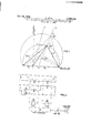
- FIG. 1 shows graphically an impedance diagram 1llustrating the impedance vectors of the power line and various components of the apparatus.
- FIG. 2 shows a circuit diagram of the apparatus according to this invention.
- the apparatus when the'phase angle is In FIGURE 2, the apparatus includes the transformers 11 and 12 having primary windings 13 and 14, respectively, which are connected in series across input terminals 15, and further primary windings 16 and 17 of these transformers are connected in parallel across input terminals 18 which, in turn, are in series with potentiometers 19 and 20.
- a phase comparator 21 has input terminals 22 23 coupled to secondary windings 24 and 25 of the two 21 and an electronic counter 27.
- phase comparator may be arranged instead to measure the phase angle between the vectors 3 R and (R Z).
- This modification however has a disadvantage in so far as the measurement of phase angle is now much more dependent on the value of the arc resistance occurring during an electrical fault, thus rendering the distance measurements less accurate than before.
- an electronic counter has been described as the output device, a capacitor may alternatively be used, charged by the output from the phase comparator, so that the resultant voltage across this capacitor becomes a measure of the distance to the electrical earth fault on the line. This arrangement would be advantageous where several power lines, at a sub-station for example, incorporate such an electrical apparatus, so that an electrostatic voltmeter may be used to measure the resultant voltage associated with each power line.
- Apparatus for measuring from a reference datum the distance to a load point along an electrical line having a predetermined load locus on an R-X operating characteristic of said apparatus comprising a pair of replica impedances defining predetermined impedance vectors intersecting the said datum on the characteristic, means for monitoring the current and voltage of the line and applying one of these quantities to said replica impedances, means for deriving from the monitored quantities two like vectorial components each dependent on said impedance vector and at least one of which is dependent also on the ratio of the monitored voltage and current signals in a manner such as to intersect the load locus at said load point, and a phase comparator for determining the phase difierence between the two components whereby to derive therefrom a measurement of the said distance.
Landscapes
- Physics & Mathematics (AREA)
- General Physics & Mathematics (AREA)
- Locating Faults (AREA)
- Emergency Protection Circuit Devices (AREA)
Description
Oct. 29, 1968 HOEL 3,408,564
ELECTRICAL APPARATUS INCLUDING A PAIR OF REPLICA IMPEDANCES FOR MEASURING DISTANCES ALONG A LOADED ELECTRICAL LINE Filed Feb. 1, 1965 REACTANCE FIG. 1
OR RA A EsEFArEF ELECTRONIC COUNTER United States Patent DISTANCES ALONG A LOADED ELECTRICAL LINE Hans Hoel, Oslo, Norway, assignor to The English Electric Company Limited, London, England, a British company Filed Feb. 1, 1965, Ser. No. 429,216 priority, application Great Britain, Feb. 5, 1964,
4,863/64 5 Claims. (Cl. 324-52) Claims invention relates to electrical apparatus for measuring the line, and more which the load point is an earth fault aflecting an electrical power supply line. From one aspect, apparatus pendent on the distance measurement.
It is to be understood, however, that the invention is not necessarily limited to power lines and fault distance be described, by Way of example, with reference to an accompanying drawing in which:
FIG. 1 shows graphically an impedance diagram 1llustrating the impedance vectors of the power line and various components of the apparatus; and
3,408,564 Patented Oct. 29, 1968 FIG. 2 shows a circuit diagram of the apparatus according to this invention.
Referring now to the drawings, in FIG.
when the'phase angle is In FIGURE 2, the apparatus includes the transformers 11 and 12 having primary windings 13 and 14, respectively, which are connected in series across input terminals 15, and further primary windings 16 and 17 of these transformers are connected in parallel across input terminals 18 which, in turn, are in series with potentiometers 19 and 20.
A phase comparator 21 has input terminals 22 23 coupled to secondary windings 24 and 25 of the two 21 and an electronic counter 27.
line applied to input terminals 21 is arranged to measure the thus representing the impedance vectors (R Z) and (R -f-Z). The resulting output signal from the phase then protective action may be It is to be understood that to the particular arrangement described and illustrated.
and magnitudes or angular positions in-line with the vector Z.
Furthermore, the phase comparator may be arranged instead to measure the phase angle between the vectors 3 R and (R Z). This modification however has a disadvantage in so far as the measurement of phase angle is now much more dependent on the value of the arc resistance occurring during an electrical fault, thus rendering the distance measurements less accurate than before. In addition, although an electronic counter has been described as the output device, a capacitor may alternatively be used, charged by the output from the phase comparator, so that the resultant voltage across this capacitor becomes a measure of the distance to the electrical earth fault on the line. This arrangement would be advantageous where several power lines, at a sub-station for example, incorporate such an electrical apparatus, so that an electrostatic voltmeter may be used to measure the resultant voltage associated with each power line.
What I claim as my invention and desire to secure by Letters Patent is:
1. Apparatus for measuring from a reference datum the distance to a load point along an electrical line having a predetermined load locus on an R-X operating characteristic of said apparatus, comprising a pair of replica impedances defining predetermined impedance vectors intersecting the said datum on the characteristic, means for monitoring the current and voltage of the line and applying one of these quantities to said replica impedances, means for deriving from the monitored quantities two like vectorial components each dependent on said impedance vector and at least one of which is dependent also on the ratio of the monitored voltage and current signals in a manner such as to intersect the load locus at said load point, and a phase comparator for determining the phase difierence between the two components whereby to derive therefrom a measurement of the said distance.
2. Apparatus according to claim 1, wherein the two vectorial quantities are each dependent on both the said impedance vector and the ratio of the monitored voltage and current signals.
3. Apparatus according to claim 2, wherein the reference datum is the origin of the operating characteristic and the impedance vector is purely resistive.
4. Apparatus according to claim 3, wherein the two like vectorial quantities are currents, one being dependent on the sum of the resistive vector extending from one side of said origin and the ratio of the monitored voltage and current signals and the other being dependent on the difference between the resistive vector extending from the opposite side of the origin and the said ratio.
5. Apparatus according to claim 1, wherein the load locus is predetermined for earth faults in an electrical power supply line.
No references cited.
RUDOLPH V. ROLINEC, Primary Examiner. G. R. STRECKER, Assistant Examiner.
Claims (1)
1. APPARATUS FOR MEASURING FROM A REFERENCE DATUM THE DISTANCE TO A LOAD POINT ALONG AN ELECTRICAL LINE HAVING A PREDETERMINED LOAD LOCUS ON AN R-X OPERATING CHARACTERISTIC OF SAID APPARATUS, COMPRISING A PAIR OF REPLICA IMPEDANCES DEFINING PREDETERMINED IMPEDANCE VECTORS INTERSECTING THE SAID DATUM ON THE CHARACTERISTIC, MEANS FOR MONITORING THE CURRENT AND VOLTAGE OF THE LINE AND APPLYING ONE OF THESE QUANTITIES TO SAID REPLICA IMPEDANCES, MEANS FOR DERIVING FROM THE MONITORED QUANTITIES TWO
Applications Claiming Priority (1)
| Application Number | Priority Date | Filing Date | Title |
|---|---|---|---|
| GB486364A GB1093021A (en) | 1964-02-05 | 1964-02-05 | Electrical apparatus for measuring distances along electrical lines |
Publications (1)
| Publication Number | Publication Date |
|---|---|
| US3408564A true US3408564A (en) | 1968-10-29 |
Family
ID=9785235
Family Applications (1)
| Application Number | Title | Priority Date | Filing Date |
|---|---|---|---|
| US42921665 Expired - Lifetime US3408564A (en) | 1964-02-05 | 1965-02-01 | Electrical apparatus including a pair of replica impedances for measuring distances along a loaded electrical line |
Country Status (5)
| Country | Link |
|---|---|
| US (1) | US3408564A (en) |
| JP (1) | JPS432980B1 (en) |
| CH (1) | CH424977A (en) |
| FR (1) | FR1423541A (en) |
| GB (1) | GB1093021A (en) |
Cited By (5)
| Publication number | Priority date | Publication date | Assignee | Title |
|---|---|---|---|---|
| US3470331A (en) * | 1966-12-29 | 1969-09-30 | Bell Telephone Labor Inc | Fault-generated surge responsive fault locating system for frequency division multiplexed transmission facilities |
| US3593124A (en) * | 1967-06-01 | 1971-07-13 | Compteurs Comp D | Method and device for detecting and localizing phase-to-phase and phase-to-earth faults which occur in a section of a polyphase alternating current line |
| US4063163A (en) * | 1975-06-12 | 1977-12-13 | Bbc Brown Boveri & Company Limited | Apparatus for localization of a line fault through the use of predeterminably shiftable reference location |
| EP0239268A3 (en) * | 1986-03-07 | 1988-08-03 | Mitsubishi Denki Kabushiki Kaisha | Fault point locating method, fault point resistance measuring method, and impedance to fault point measuring method, and apparatus therefor |
| US20140232416A1 (en) * | 2012-12-21 | 2014-08-21 | Centre National D'etudes Spatiales Cnes | System and method for detecting and locating an insulation flaw in a solar generator on a space vehicle |
Families Citing this family (2)
| Publication number | Priority date | Publication date | Assignee | Title |
|---|---|---|---|---|
| RU2289142C1 (en) * | 2005-07-04 | 2006-12-10 | Государственное образовательное учреждение высшего профессионального образования "Таганрогский государственный радиотехнический университет" (ТРТУ) | Device for measuring isolation resistance |
| JP5962567B2 (en) | 2013-04-09 | 2016-08-03 | 信越化学工業株式会社 | Oil-in-water sunscreen cosmetics |
-
1964
- 1964-02-05 GB GB486364A patent/GB1093021A/en not_active Expired
-
1965
- 1965-02-01 US US42921665 patent/US3408564A/en not_active Expired - Lifetime
- 1965-02-02 JP JP527065A patent/JPS432980B1/ja active Pending
- 1965-02-04 CH CH151565A patent/CH424977A/en unknown
- 1965-02-05 FR FR4516A patent/FR1423541A/en not_active Expired
Non-Patent Citations (1)
| Title |
|---|
| None * |
Cited By (6)
| Publication number | Priority date | Publication date | Assignee | Title |
|---|---|---|---|---|
| US3470331A (en) * | 1966-12-29 | 1969-09-30 | Bell Telephone Labor Inc | Fault-generated surge responsive fault locating system for frequency division multiplexed transmission facilities |
| US3593124A (en) * | 1967-06-01 | 1971-07-13 | Compteurs Comp D | Method and device for detecting and localizing phase-to-phase and phase-to-earth faults which occur in a section of a polyphase alternating current line |
| US4063163A (en) * | 1975-06-12 | 1977-12-13 | Bbc Brown Boveri & Company Limited | Apparatus for localization of a line fault through the use of predeterminably shiftable reference location |
| EP0239268A3 (en) * | 1986-03-07 | 1988-08-03 | Mitsubishi Denki Kabushiki Kaisha | Fault point locating method, fault point resistance measuring method, and impedance to fault point measuring method, and apparatus therefor |
| US20140232416A1 (en) * | 2012-12-21 | 2014-08-21 | Centre National D'etudes Spatiales Cnes | System and method for detecting and locating an insulation flaw in a solar generator on a space vehicle |
| US9506972B2 (en) * | 2012-12-21 | 2016-11-29 | Airbus Defence And Space Sas | System and method for detecting and locating an insulation flaw in a solar generator on a space vehicle |
Also Published As
| Publication number | Publication date |
|---|---|
| GB1093021A (en) | 1967-11-29 |
| CH424977A (en) | 1966-11-30 |
| FR1423541A (en) | 1966-01-03 |
| JPS432980B1 (en) | 1968-02-02 |
Similar Documents
| Publication | Publication Date | Title |
|---|---|---|
| US2059594A (en) | Electrical measuring instrument | |
| US3248646A (en) | Location of cable faults by comparing a section of the faulted cable with a part of the section | |
| US3408564A (en) | Electrical apparatus including a pair of replica impedances for measuring distances along a loaded electrical line | |
| Wedepohl | Polarised mho distance relay. New approach to the analysis of practical characteristics | |
| US4841228A (en) | Apparatus for indicating the resistive characteristic of a capacitor | |
| US3281677A (en) | Means for determining the self or earth impedance of an electric supply system by producing an indication when the magnitude of the current exceeds that for the maximum permissible impedance | |
| SE7710752L (en) | PROCEDURE AND DEVICE FOR MONITORING AN ELECTRICAL CABLE REGARDING SHORT CIRCUITS | |
| US3842344A (en) | Bridge circuit for measuring dielectric properties of insulation | |
| US1684056A (en) | Electrical measuring instrument | |
| US3562647A (en) | Power factor transducer having voltage and current responsive switching means biased by an intermittently generated voltage | |
| GB1178231A (en) | Improvements in or relating to methods and apparatus for locating faults in the conductors of cables. | |
| DE1922025C3 (en) | Method and device for determining the one-, two- or three-phase short school currents in three-phase electrical networks | |
| JPH0373825B2 (en) | ||
| DE862189C (en) | Measuring circuit for the ongoing monitoring of electrical cables, especially when laying submarine cables, and a cable testing device set up afterwards | |
| GB1007456A (en) | Discharge simulator | |
| US2785378A (en) | Electrical measuring system | |
| US3172038A (en) | Double bridge circuit for measuring resistance of energized alternating current apparatus | |
| RU2828439C1 (en) | Method of determining point of damage on overhead power transmission line by measuring currents from its two ends | |
| US1691342A (en) | Measuring instrument | |
| RU2823691C1 (en) | Method of determining the point of damage on overhead power transmission line by measuring currents from its two ends | |
| JPS57203967A (en) | Digital meter of voltage, current and phase defference | |
| US1535624A (en) | Electrical system | |
| US2458805A (en) | Apparatus for measuring electrical resistance | |
| SU1659880A1 (en) | Method for measuring electric immitance | |
| GB797399A (en) | Improvements in or relating to apparatus for making electrical measurements upon coated conductors |