US3402665A - Nonpyrotechnic disseminator - Google Patents
Nonpyrotechnic disseminator Download PDFInfo
- Publication number
- US3402665A US3402665A US572473A US57247366A US3402665A US 3402665 A US3402665 A US 3402665A US 572473 A US572473 A US 572473A US 57247366 A US57247366 A US 57247366A US 3402665 A US3402665 A US 3402665A
- Authority
- US
- United States
- Prior art keywords
- container
- disseminator
- liquefied gas
- contents
- gelled
- Prior art date
- Legal status (The legal status is an assumption and is not a legal conclusion. Google has not performed a legal analysis and makes no representation as to the accuracy of the status listed.)
- Expired - Lifetime
Links
Images

Classifications
-
- C—CHEMISTRY; METALLURGY
- C06—EXPLOSIVES; MATCHES
- C06D—MEANS FOR GENERATING SMOKE OR MIST; GAS-ATTACK COMPOSITIONS; GENERATION OF GAS FOR BLASTING OR PROPULSION (CHEMICAL PART)
- C06D3/00—Generation of smoke or mist (chemical part)
-
- C—CHEMISTRY; METALLURGY
- C06—EXPLOSIVES; MATCHES
- C06D—MEANS FOR GENERATING SMOKE OR MIST; GAS-ATTACK COMPOSITIONS; GENERATION OF GAS FOR BLASTING OR PROPULSION (CHEMICAL PART)
- C06D7/00—Compositions for gas-attacks
-
- F—MECHANICAL ENGINEERING; LIGHTING; HEATING; WEAPONS; BLASTING
- F42—AMMUNITION; BLASTING
- F42B—EXPLOSIVE CHARGES, e.g. FOR BLASTING, FIREWORKS, AMMUNITION
- F42B12/00—Projectiles, missiles or mines characterised by the warhead, the intended effect, or the material
- F42B12/02—Projectiles, missiles or mines characterised by the warhead, the intended effect, or the material characterised by the warhead or the intended effect
- F42B12/36—Projectiles, missiles or mines characterised by the warhead, the intended effect, or the material characterised by the warhead or the intended effect for dispensing materials; for producing chemical or physical reaction; for signalling ; for transmitting information
- F42B12/46—Projectiles, missiles or mines characterised by the warhead, the intended effect, or the material characterised by the warhead or the intended effect for dispensing materials; for producing chemical or physical reaction; for signalling ; for transmitting information for dispensing gases, vapours, powders or chemically-reactive substances
- F42B12/50—Projectiles, missiles or mines characterised by the warhead, the intended effect, or the material characterised by the warhead or the intended effect for dispensing materials; for producing chemical or physical reaction; for signalling ; for transmitting information for dispensing gases, vapours, powders or chemically-reactive substances by dispersion
-
- F—MECHANICAL ENGINEERING; LIGHTING; HEATING; WEAPONS; BLASTING
- F42—AMMUNITION; BLASTING
- F42B—EXPLOSIVE CHARGES, e.g. FOR BLASTING, FIREWORKS, AMMUNITION
- F42B27/00—Hand grenades
Definitions
- This invention has as an object the provision of a r nonpoyrotechnic disseminator.
- This invention has as another object the provision of a nonpyrotechnic disseminator which achieves dissemination of solids, such as solids in the form of powders or leaflets, over a wide area.
- This invention has as another object the provision of a disseminator which may be safely stored, handled and used.
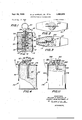
- FIGURE 1 is a vertical sectional view of an embodiment of the nonpyrotechnic disseminator of the present invention.
- FIGURE 2 is a plan view, looking down from above, of the nonpyrotechnic disseminator of FIGURE 1.
- FIGURE 3 is a cross-sectional view taken on line 33 of FIGURE 1.
- FIGURE 4 is a vertical sectional view of another embodiment of the nonpyrotechnic disseminator of the present invention.
- FIGURES 5 to 7 are sectional views of other embodiments of the nonpyrotechnic disseminator of the present, invention.
- FIGURE 8 is a partial horizontal cross-sectional view of the embodiment shown in FIGURE 7, showing details of the means for opening the disseminator.
- FIGURE 9 is a longitudinal cross-sectional view of still another embodiment of the nonpyrotechnic disseminator of the present invention.
- FIGURE 10 is a detailed view showing a portion of the embodiment of the nonpyrotechnic disseminator of FIG- URE 9.
- FIGURE 11 is a vertical sectional view of another embodiment of a nonpyrotechnic disseminator.
- the disseminator 10 comprises the shell 12 within which is disposed the block 14.
- the block 14 contains a central bore 16 within which is disposed the firing pin 18.
- the firing pin 18 comprises the finger grip 20 at the top end of the pin member 22 and the frusto-conical head 24 at the bottom end of the pin member 22.
- the firing pin 18 is guided within the central bore 16 by the O-ring 26, and by the frusto-conical head 24.
- the O-ring 26 is disposed within an O-ring groove located at the top portion of the block 14.
- the uppermost end 28 of the block 14 comprises a stop shoulder.
- Each capsule comprises a cylinder of teargas powder and of gelled liquefied gas, such as the formulation set forth below in Example 1.
- the base of each of the capsules 30, 32, 34, 36, and 38 and 40 is reinforced and is disposed against the inner face of the shell 12.
- the innermost end of each of the capsules 30, 32, 34, 36, 38 and 40 comprises a diaphragm, such as a metal foil diaphragm, which may be ultrasonically ring welded or otherwise joined to the capsules.
- Such diaphragm faces the needles 42, 44, 46, 48, and 52, which are radially disposed in bores 54, 56, 58, 60, 62 and 64, which communicate with the central bore 16-.
- Each of the needles 42, 44, 46, 48, 50 and 52 are hollow.
- the firing pin 18 is engaged with a spring-urged ball plunger 66.
- the ball head of the plunger 66 may be cammed into circular grooves in the wall of the firing pin 18, so that the ball plunger functions as a click or detent.
- the O-ring 26 provides an effective seal to the uppermost end of the disseminator 10.
- the user grasps the finger grip 20, and commences to pull it away from the shell 12.
- the frusto-conical head 24 engages the needle 42 it urges the same through the diaphragm in the capsule 30.
- the puncturing of the diaphragm of the capsule 30 results in the gasifieation of the gelled liquefied gas within the capsule 30, and the powder contents Within the capsule 30 issues rapidly outwardly propelled by the gasification of the liquefied gas.
- the issuance of such powder inventory from the capsule 30 is through the opening '68 at the lower end of the central bore 16.
- the ball plunger 66 enables the user to discharge the disseminator in stages, since the seating of the ball plunger 66 in the semicircular grooves in the firing pin 18 will indicate to the user when each capsule is being punctured. In an emergency situation, the user can rapidly pull the firing pin out for its entire length and discharge the entire contents of the disseminator 10.
- the disseminator 70 comprises the container 72, which may be of conventional can construction.
- the firing mechanism 76 In the top end wall 74 of the container 72 there is positioned the firing mechanism designated generally as 76.
- the firing mechanism 76 comprises the safety handle 78 which is normally locked in nonactuatable position by the safety pin 80 which extends through both the ear 82 of safety handle 78 and the firing mechanism head 84.
- the safety pin 80 is provided with a finger grip (not shown) which enables the safety pin 80 to be pulled from its disposition within the car 82 and the firing mechanism head 84.
- the safety handle 78 retains the firing pin 86 in nonactuatable position.
- the firing pin 86 is spring-urged by the spring 88 in a clockwise direction.
- the safety handle 78 keeps the firing pin 86 away from the primer 90.
- the primer is in communication with the pyrotechnic delay column 92.
- Such pyrotechnic delay column may comprise a conventional fuse.
- the pyrotechnic delay column 92 engages the explosive charge 94.
- the explosive charge 94 is a very small one, and need have only sufficient strength to rupture the container 72.
- the contents 96 of the container 72 comprises finely divided powder disposed within a gelled liquefied gas, such as one of the lachrymator mixtures of Examples 1 through 3 set forth below.
- the user pulls the firing pin 86 from its engagement with the car 82 and the firing mechanism head 84.
- the user can still retain the safety handle 78 in the disposition shown in FIGURE 4 by gripping the same.
- the safety handle 78 flies upward due to the spring-urging of the spring 88.
- the firing pin 86 ignites the primer 90.
- the pyrotechnic delay column furnishes a time delay prior to exploding the explosive charge 94 which ruptures the container 72.
- the gelled liquefied gas in container 72 is rapidly gasified and dispenses the contents 96 in all directions.
- the disseminator 70 is an omnidirectional disseminator, as the contents 96 are discharged in all directions on the rupturing of the container 72 (unlike the controlled directional dissemination which results from the use of the disseminator 10 of FIGURES 1 through 3).
- the disseminator 100 of FIGURE is another omnidirectional disseminator, and spews its contents in all directions.
- the disseminator 100 comprises a spherical container 102 for-med of thin walled metal, such as aluminum, with pressure containing capability.
- the container 102 is provided with a fill opening 104 sealed by a welded closure, such as a closure that has been ultrasonically ring welded to the spherical container 102.
- a puncturing means 106 comprising a sharp pointed metal spider is disposed within the spherical container 102 (the spherical container 102 may be formed from two hemispheres, with the puncturing means 106 disposed within the same prior to the welding together of the hemispheres).
- the contents 108 comprising finely divided powders disposed within a gelled liquefied gas are contained within the container 102.
- the container 102 In use, the container 102 is hurled against a surface causing the spider 106 to rupture the container 102. This results in the immediate gasification of the gelled liquefied gas, which dispenses the finely divided powder in all directions.
- the disseminator 110 of FIGURE 6 comprises a directional disseminator.
- the disseminator 110 comprises the container body 112, to which is applied the container cap 114.
- a tight seal is secured between the container body 112 and the container cap 114 by the O-ring 116.
- the contents 118 of the disseminator may be radar marker materials, or message disseminators, or fibers, such as those of Examples 22, 23 and 24 set forth below, which include a gelled liquefied gas.
- the contents 118 are under superatmospheric pressure, such as a pressure of the order of 100 to pounds per square inch.
- the C-clamp 120 which is provided with lugs 122 holds the container cap 114 onto the container body 112.
- a pyrofuse wire 124 extends through the ears 126 on the side of container body 112 and through the lugs 122 of the C-clamp 120.
- the pyrofuse wire 124 is heated. This causes the wire to melt and leads to its destruction.
- the internal pressure within the disseminator 110 pushes the container cap 114 away from the container body 112.
- the gasification of the gelled liquefied gas within the container body 112 immediately ensues, whereby the contents 118 are discharged through the open mouth of the container body 112. This results in the directional discharge of the contents 118.
- the disseminator 128 of FIGURE 7 comprises a disseminator for the distribution of leaflets or other flat materials, such as radar marker materials.
- the disseminator 128 comprises a generally cylindrical container body designated by 130.
- the container body 130 is defined by several longitudinally extending Wall segments 132.
- the wall segments 132 include outwardly extending hooked ends 134 and 136. End sections 138 and 140 are disposed at opposite ends of the container body 130, in engagement with the hooked ends 134.
- An annular restraining band 142 having a generally semicircular cross-section extends annularly of a container body 130, in engagement with the hooked ends 136.
- a toggle mechanism is effective to hold the annular restraining band 142 in contact with the hooked ends 136.
- Such toggle mechanism includes an actuating lever 146, pivotably secured by means of a pin 148 to one end of the restraining band 142.
- a toggle link 150 is pivotably secured to the other end of the restraining band 142.
- the toggle link 150 is pivotably secured to one end of the actuating lever 146.
- a pair of upstanding ears 152 is secured to the restraining band 142 adjacent its other end.
- a safety pin 154 extends between the ears 152 in overlying relation to the actuating lever 146 to prevent operation of the mechanism.
- a metal foil container 156 Disposed within the container body 130 is a metal foil container 156.
- the metal foil container which may be fabricated by ultrasonic ring welding, is not strong enough by itself to maintain normal internal pressure.
- the above-described container body 130 serves to prevent rupture of the metal foil container 156.
- contents 158 which may comprise leaflets or other materials within a gelled liquefied gas.
- the safety pin 154 is removed, and the container 130 hurled against a surface, thereby causing deformation of the container body, and operation of the mechanism 144. Accordingly, the metal foil container 156, without the support of the container body 130, ruptures, thereby causing dissemination of the contents 158.
- the disseminator 160 of FIGURE 9 comprises a selfpropelled disseminator, adapted to leave a trail of material.
- the disseminator 160 comprises a body 162 having at one end a foamed elastomer tip 164 and adjacent the other a nozzle 166.
- the nozzle 166 is normally closed by a meltable plug 168 and is slightly recessed from the end of the body 162.
- a primer 170 is packed around the meltable plug 168 and has a fuse 172 embedded therein.
- the contents 174 of the disseminator 160' may be noxious substances, such as those of Examples 1 to 10 and 13 and 14, set forth below, or smoke or other markers as in Examples 11, to 19 and 24, or a combination of both, such as Example 12.
- the disseminator 160 functions as a self-propelled rocket.
- the contents are expelled forcefully through the nozzle, and accordingly, function as a rocket propellant.
- the container moves forward and leaves a trail of material.
- the elastomeric tip 164 prevents injuries to persons hit -by the disseminator.
- the dissemination 160 can also be fired from a gun, in which case the fuse and primer are ignited by the gun flash. Thus, the ejection of the material begins while the disseminator is already in flight.
- the disseminator 176 of FIGURE 11 is somewhat similar to the disseminator 70, previously described.
- the disseminator 176 comprises a container 178 of conventional can construction.
- the container 178 includes a top end wall 180 upon which there is positioned a firing mechanism designated generally as 182.
- the firing mechanism 182 comprises a safety handle 184, a safety pin 186, and a firing pin 188, all similar to those previously described.
- the firing mechanism 182 includes a primer 190 and a pyrotechnic delay column 192 disposed in a bore 193. At the end of the'bore 193 and in contact with the delay column 192 is a solder disk 194.
- the removal of the safety pin 186 and the safety handle 184 results in actuation of the firing pin 188, and hence, ignition of the primer 190.
- the solder disk 194 is melted, and the internal pressure in the container 178 forces the contents 196 through the passage formerly occupied 'by the primer and delay column.
- the disseminator 176 unlike the disseminator 70, is unidirectional, and accordingly, can be readily aimed.
- the 'bore' 193 of the disseminator 176, as well as theopening 68 of the disseminator 10, may be referred to as nozzles.
- the present invention comprehends that the solid matter to be disseminated be disposed within a gelled liquid. It is necessary for the purposes of the present invention that the solid matter not be appreciably soluble in the gelled liquid.
- At least a part of the gelled liquid must comprise a liquefied gas, and in some embodiments all of the gelled liquid :may comprise a liquefied gas.
- the relative propor' tion, of liquefied gas to the remainder of gelled liquid is dependent upon the physical'properties of the liquefied gas and of the gelled liquid.
- the liquefied gas is relatively highly volatile, namely where it has a relatively high vapor pressure, and where it has a relatively high eX- pansion ratio, as in the case of liquefied trifiuoro bromomethane orliquefied propane
- the portion of the gelled liquid which consists of the liquefied gas may be relatively small, such as of the order of 5 weight percent of the total composition.
- compositions in which all of the gelled liquid consists of liquefied gas have primary utility Where the liquefied gas is one having a relatively low volatility, or in'whicha high propellent force is needed for a particular use application, or where the liquefied gas has the property of augmenting the functionality of the finely divided powder as in the case of liquefied Freon being used in a fire extinguisher.
- the present invention comprehends compositions consisting of from to'70 volume percent of finely divided powder, with the remainder being gelled liquid. Normally, there is no advantage in having the powder percentage below about 30 volume percent, since the desired properties of the composition are to a large degree dependent upon the amount of powder present in the composition. Generally, when the powders are present above about 70 volume percent, the flow properties and handling characteristics of the composition are adversely affected. Powders used with the present invention are generally in the range of 1 to microns in size.
- compositions of the present invention include a gelling agent, which should be present in an amount sulficient to effect gelling of all of the liquid present in the composition.
- the gelling agent should be one which has a gelling eflicacy such that no more than about 5 weight percent of the composition need be gelling agent.
- the finely divided powder possesses gelling characteristics, and the amount of gelling agent which need be present in such compositions may be reduced. Generally, at least about onehalf weight percent of gelling agent must be present to achieve satisfactory gelling of the liquid portion of the composition.
- a satisfactory gelling agent is the pyrogenic silica sold under the trademark Cab-O-Sil H5 by Godfrey L. Cabot, Inc., of Boston, Mass.
- gelling agents include: pyrogenic silica, namely finely divided silica particles derived from the combustion of silicon tetrachloride, such materials being commercially available as gelling agents under the trademark Cab-O-Sil; carbon black having a clean microsurface and a high degree of structure with said structure being internal with particles smaller than 25 millimicrons :as measured by an electron microscope and presenting a ratio of BET surface as determined by nitrogen adsorption measurement to electron microscope surface of between 2 /2 and 6 and with larger particles being external, namely possessing persistent particular chain formation observable in the electron microscope after mulling by the procedure of Ladd; pyrogenic aluminum oxide derived from the combustion of aluminum trichloride; carboxymethyl cellulose, sulphonated polyvinyl toluene; carogeenin, and guar, etc.
- a suitable pyrogenic alumina is available under the trademark Alon C.
- gelled liquid as used herein is meant a material possessing a ,yield stress sufficiently high to prevent flow under low forces such as gravitation, namely a yield stress of 200 dynes per square centimeter, is adequate.
- a surfactant as in the concentration of 0.1 to 1 weight percent based on the amount of gelled liquid present is helpful.
- suitable surfactants include: sorbitan trioleate; polyethylene glycol ether of hydroabietyl alcohol; polyoxyethylene sorbitan monooleate; diethylene glycol laurate; sulfonated castor oil; triethanolamine monooleate.
- the presence of the surfactant improves wetting of the finely divided powders and increases fiowability.
- the function of the gelled liquid is to keep the particles making up the finely divided powder from each other so that they do not adhere to each other, as by sintering or by Van der Waals attraction.
- compositions of the present invention are kept within containers of the type described above, with such containers having a structural strength sufiicient to withstand the pressures developed under storage and use temperatures. Generally, these pressures will be of the order of 15 to p.s.i.g.
- the chemical nature of the powders to be used in the compositions of the present invention will vary depending upon the use to which the powders may be put. Unlike prior dry powder dispensing compositions, it is not necessary to include flow promoting additives and antiagglomerants in the finely divided powders of the present invention. Thus, no useful purpose is served in the present invention by the addition of such flow promoting additives and/ or antiagglomerants.
- Example 3 Chloroacetophenone containing approximately 8% magnesium oxide, mulled in perfluoropropane 67.0 Perfluoropropane 32.0 Cab-O-Sil H5 1.0
- Example 6 Putre seine 45 .00 Difluorodichloromethane 53.5 Cab-O-Sil HS 1.5
- Emetic composition Example 9 Diphenylaminochloro arsine 60.0 Perfiuoropropane 38.8 Cab-O-Sil H5 1.2
- Emetic and lachrymator composition Example 10 Diphenylaminochloroarsine 30.0 Chloroacetophenone, ground at low temperature 30.0 Perfluorocyclobutane 38.8 Cab-O-Sil H5 1.2
- Example 12 Crystal violet Chloroacetophenone, ground at low temperature Perfluorocyclobutane Cab-O-Sil H5 Foam lachrymator composition
- Example 13 Chloroacetophenone, mulled in perfiuoropropane Silicone rubber prepolymer Perfluorocyclobutane Alon-C Foam composition with ofiensive odor
- Example 14 Putrescine Silicone rubber prepolymer Dichlorodifiuoromethane Cab-O-Sil H5 Red smoke composition
- Example 15 Titanium dioxide Propane Cab-O-Sil H5 Black smoke compositions
- Example 17 Carbon black (furnace black) Butane Carbon black High color channel black
- Example 18 Manganese dioxide Liquified ammonia Carbon black (high color channel black) Metallic smoke compositions
- Example 19 Aluminum flake Butane Green smoke composition
- Example 20 Chromic oxide Butane Al0n C Violet smoke composition
- Example 21 1,4-diamino-2,3-dihydro anth
- Apparatus for disseminating particulate material comprising a closed container, a composition in said container comprising a gelled liquid having a yield stress of at least 200 dynes per square centimeter, particulate ma terial disposed within and substantially insoluble in said gelled liquid, said particulate material comprising from 30 to 70 volume percent of said composition, at least a portion of said gelled liquid comprising a liquefied gas so that vaporization of said liquefied gas creates a positive pressure inside said container, and means coupled to said container whereby said container may be opened to permit ejection of its contents.
- said container is in the form of an elongated tubular projectile having a fixed closure at one end and a nozzle at the other end, said means for opening said container comprising a heat fusible plug member normally blocking said nozzle, a combustible primer adjacent said plug member, and means coupled to said primer for igniting the same, buming of said primer being effective to melt said plug and thereby open said container.
- Apparatus in accordance with claim 1 wherein a plurality of said containers are disposed in a block, a central bore in said block, a plurality of bores in said block extending outwardly from and in fluid communication with said central bore spaced at positions therealong, said containers being disposed in said outwardly extending bores, said means for opening said container comprising rod means movable axially of said central bore, and means responsive to movement of said rod means for piercing each container so that the contents of each container are ejected into said central bore.
- said container is a vessel having walls sutficiently thin to permit deformation upon impact with a rigid surface
- said means for opening said container comprising, a rigid spider member having sharply pointed ends disposed in said container with its ends in contact with the inner surface of the container so that said ends are adapted to pierce the container upon impact of the apparatus with a rigid surface.
- said container comprises a container body and a container cap, means clamping said container cap to said container body, said means clamping said container cap to said container body being secured by a pyrofuse wire so that melting of said wire releases said clamping means.
- said container comprises an inner container member having tensile strength insufficient to retain said particulate material and gelled liquid, and an outer container member, said outer container member comprising a plurality of assembled sections and restraining means for maintaining said sections in assembled relation, said means for opening said container comprising means for releasing said restraining means.
- said container includes a bore, said means for opening said container comprising a primer and a pyrotechnic delay column, said primer and pyrotechnic delay column being disposed in said bore, and a plug of meltable material at the end of said pyrotechnic delay column and closing said bore so that burning of said delay column melts the plug to permit ejection of the contents of the container.
- Apparatus in accordance with claim 12 including a spring-urged pin for igniting said primer, and a safety handle for maintaining said pin in an inactive position.
Landscapes
- Chemical & Material Sciences (AREA)
- Engineering & Computer Science (AREA)
- Combustion & Propulsion (AREA)
- Organic Chemistry (AREA)
- General Engineering & Computer Science (AREA)
- Life Sciences & Earth Sciences (AREA)
- Botany (AREA)
- Pest Control & Pesticides (AREA)
- Plant Pathology (AREA)
- Dispersion Chemistry (AREA)
- Filling Or Discharging Of Gas Storage Vessels (AREA)
Description
Priority Applications (1)
| Application Number | Priority Date | Filing Date | Title |
|---|---|---|---|
| US572473A US3402665A (en) | 1966-08-15 | 1966-08-15 | Nonpyrotechnic disseminator |
Applications Claiming Priority (1)
| Application Number | Priority Date | Filing Date | Title |
|---|---|---|---|
| US572473A US3402665A (en) | 1966-08-15 | 1966-08-15 | Nonpyrotechnic disseminator |
Publications (1)
| Publication Number | Publication Date |
|---|---|
| US3402665A true US3402665A (en) | 1968-09-24 |
Family
ID=24287961
Family Applications (1)
| Application Number | Title | Priority Date | Filing Date |
|---|---|---|---|
| US572473A Expired - Lifetime US3402665A (en) | 1966-08-15 | 1966-08-15 | Nonpyrotechnic disseminator |
Country Status (1)
| Country | Link |
|---|---|
| US (1) | US3402665A (en) |
Cited By (18)
| Publication number | Priority date | Publication date | Assignee | Title |
|---|---|---|---|---|
| US3678851A (en) * | 1970-01-12 | 1972-07-25 | Uarco Inc | Imprinting attachment for autographic registers |
| US3938708A (en) * | 1974-08-15 | 1976-02-17 | Norman D. Burger | Aerosol dispensing system |
| US3974945A (en) * | 1975-01-27 | 1976-08-17 | Norman D. Burger | Aerosol dispensing system |
| USRE30093E (en) * | 1975-01-27 | 1979-09-11 | Aerosol dispensing system | |
| US4226727A (en) * | 1978-07-21 | 1980-10-07 | Energy & Minerals Research Co. | Persistent fire suppressant composition |
| US4291629A (en) * | 1978-04-10 | 1981-09-29 | The United States Of America As Represented By The Secretary Of The Army | Combined T-shape smoke projectile and launching assembly |
| US4367799A (en) * | 1978-09-26 | 1983-01-11 | Energy & Minerals Research Co. | Apparatus for continuous discharge of material at localized damage point |
| US4944521A (en) * | 1989-06-27 | 1990-07-31 | Greeno Donald R | War game marking grenade |
| WO1991001479A3 (en) * | 1989-07-19 | 1991-03-07 | Gustav Thorban | Dye-spray generator |
| US5069134A (en) * | 1990-06-08 | 1991-12-03 | Def-Tec Corporation | Flameless expulsion grenade |
| EP0557200A1 (en) * | 1992-02-21 | 1993-08-25 | Etienne Lacroix - Tous Artifices Sa | Method and device for neutralising a threat through the release of a neutralising substance |
| WO1999065847A3 (en) * | 1998-06-01 | 2000-03-09 | Vrp Eco Tek Corp | Malodorant compositions, related non-lethal weapon systems, and methods of their use |
| US6250226B1 (en) * | 1996-06-21 | 2001-06-26 | Etienne Lacroix Tous Artifices S.A. | Non-lethal ammunition with incapacitating effect |
| US20100199960A1 (en) * | 2007-09-18 | 2010-08-12 | Chong Carlton Le Loong | Reusable pellet shooting grenade |
| US20110048273A1 (en) * | 2009-08-28 | 2011-03-03 | Antonio Colon | Non-Pyrotechnic Explosive Device Simulator |
| WO2014033049A1 (en) * | 2012-08-28 | 2014-03-06 | Rheinmetall Waffe Munition Gmbh | Irritation projectile |
| US10663272B1 (en) * | 2018-11-06 | 2020-05-26 | The United States Of America As Represented By The Secretary Of The Army | Low toxicity, environmentally friendly violet smoke generating compositions and methods of making the same |
| US20220373310A1 (en) * | 2019-09-12 | 2022-11-24 | Carl Salmon | Grenade with independently detachable carpel segments |
Citations (13)
| Publication number | Priority date | Publication date | Assignee | Title |
|---|---|---|---|---|
| US1548693A (en) * | 1924-05-15 | 1925-08-04 | Fleming R Weaver | Firing mechanism for pyrotechnics and the like |
| US1878489A (en) * | 1931-07-13 | 1932-09-20 | Byron C Goss | Generation of persistent disabling gases |
| US2079008A (en) * | 1934-10-27 | 1937-05-04 | Us Ordnance Engineers Inc | Repeating candle |
| US2112758A (en) * | 1935-05-04 | 1938-03-29 | Blacker Latham Valenti Stewart | Projectile |
| US2294415A (en) * | 1938-12-02 | 1942-09-01 | Lewis M Mcbride | Grenade |
| US2476302A (en) * | 1944-10-27 | 1949-07-19 | Morris R Jeppson | Self-propelled projectile for distributing material |
| US3014844A (en) * | 1957-01-31 | 1961-12-26 | Riker Laboratories Inc | Self-propelling powder dispensing compositions |
| US3049080A (en) * | 1959-04-17 | 1962-08-14 | Schermuly Pistol Rocket App | Rockets and rocket-borne distress signals |
| US3068472A (en) * | 1959-06-08 | 1962-12-11 | Aria Paul S Dell | Method of blowing radar-reflective dipoles astern of a moving seagoing ship |
| US3134720A (en) * | 1962-06-27 | 1964-05-26 | Bristol Myers Co | Medicated gels |
| CA705643A (en) * | 1959-08-24 | 1965-03-16 | Her Majesty's Principal Secretary Of State For The War Department In Her Majesty's Goverment Of The United Kingdom Of Great Britain And Northern Ireland | Riot-control apparatus |
| US3242270A (en) * | 1961-04-10 | 1966-03-22 | George E Van Volkenburg | Rotary switch assembly with coupling means and rotatable conductive slip ring structure |
| US3269313A (en) * | 1965-01-18 | 1966-08-30 | William G Willmann | Self-propelled sub-munition |
-
1966
- 1966-08-15 US US572473A patent/US3402665A/en not_active Expired - Lifetime
Patent Citations (13)
| Publication number | Priority date | Publication date | Assignee | Title |
|---|---|---|---|---|
| US1548693A (en) * | 1924-05-15 | 1925-08-04 | Fleming R Weaver | Firing mechanism for pyrotechnics and the like |
| US1878489A (en) * | 1931-07-13 | 1932-09-20 | Byron C Goss | Generation of persistent disabling gases |
| US2079008A (en) * | 1934-10-27 | 1937-05-04 | Us Ordnance Engineers Inc | Repeating candle |
| US2112758A (en) * | 1935-05-04 | 1938-03-29 | Blacker Latham Valenti Stewart | Projectile |
| US2294415A (en) * | 1938-12-02 | 1942-09-01 | Lewis M Mcbride | Grenade |
| US2476302A (en) * | 1944-10-27 | 1949-07-19 | Morris R Jeppson | Self-propelled projectile for distributing material |
| US3014844A (en) * | 1957-01-31 | 1961-12-26 | Riker Laboratories Inc | Self-propelling powder dispensing compositions |
| US3049080A (en) * | 1959-04-17 | 1962-08-14 | Schermuly Pistol Rocket App | Rockets and rocket-borne distress signals |
| US3068472A (en) * | 1959-06-08 | 1962-12-11 | Aria Paul S Dell | Method of blowing radar-reflective dipoles astern of a moving seagoing ship |
| CA705643A (en) * | 1959-08-24 | 1965-03-16 | Her Majesty's Principal Secretary Of State For The War Department In Her Majesty's Goverment Of The United Kingdom Of Great Britain And Northern Ireland | Riot-control apparatus |
| US3242270A (en) * | 1961-04-10 | 1966-03-22 | George E Van Volkenburg | Rotary switch assembly with coupling means and rotatable conductive slip ring structure |
| US3134720A (en) * | 1962-06-27 | 1964-05-26 | Bristol Myers Co | Medicated gels |
| US3269313A (en) * | 1965-01-18 | 1966-08-30 | William G Willmann | Self-propelled sub-munition |
Cited By (27)
| Publication number | Priority date | Publication date | Assignee | Title |
|---|---|---|---|---|
| US3678851A (en) * | 1970-01-12 | 1972-07-25 | Uarco Inc | Imprinting attachment for autographic registers |
| US3938708A (en) * | 1974-08-15 | 1976-02-17 | Norman D. Burger | Aerosol dispensing system |
| US3974945A (en) * | 1975-01-27 | 1976-08-17 | Norman D. Burger | Aerosol dispensing system |
| USRE30093E (en) * | 1975-01-27 | 1979-09-11 | Aerosol dispensing system | |
| US4291629A (en) * | 1978-04-10 | 1981-09-29 | The United States Of America As Represented By The Secretary Of The Army | Combined T-shape smoke projectile and launching assembly |
| US4226727A (en) * | 1978-07-21 | 1980-10-07 | Energy & Minerals Research Co. | Persistent fire suppressant composition |
| US4367799A (en) * | 1978-09-26 | 1983-01-11 | Energy & Minerals Research Co. | Apparatus for continuous discharge of material at localized damage point |
| US4944521A (en) * | 1989-06-27 | 1990-07-31 | Greeno Donald R | War game marking grenade |
| WO1991001479A3 (en) * | 1989-07-19 | 1991-03-07 | Gustav Thorban | Dye-spray generator |
| US5069134A (en) * | 1990-06-08 | 1991-12-03 | Def-Tec Corporation | Flameless expulsion grenade |
| EP0557200A1 (en) * | 1992-02-21 | 1993-08-25 | Etienne Lacroix - Tous Artifices Sa | Method and device for neutralising a threat through the release of a neutralising substance |
| FR2687773A1 (en) * | 1992-02-21 | 1993-08-27 | Lacroix E Tous Artifices | METHOD AND DEVICE FOR NEUTRALIZING A THREAT BY DEPLOYING A NEUTRALIZING SUBSTANCE FORMING SCREEN BETWEEN THE THREAT AND A ZONE TO BE PROTECTED |
| US6250226B1 (en) * | 1996-06-21 | 2001-06-26 | Etienne Lacroix Tous Artifices S.A. | Non-lethal ammunition with incapacitating effect |
| US6386113B1 (en) | 1997-09-25 | 2002-05-14 | Ecological Technologies Corporation | Non-lethal weapon systems |
| US6242489B1 (en) | 1997-09-25 | 2001-06-05 | Ecological Technologies Corporation | Malodorant compositions |
| US6352032B1 (en) | 1997-09-25 | 2002-03-05 | Ecological Technologies Corporation | Malodorant compositions, related non-lethal weapon systems, and methods of their use |
| WO1999065847A3 (en) * | 1998-06-01 | 2000-03-09 | Vrp Eco Tek Corp | Malodorant compositions, related non-lethal weapon systems, and methods of their use |
| US20100199960A1 (en) * | 2007-09-18 | 2010-08-12 | Chong Carlton Le Loong | Reusable pellet shooting grenade |
| US7784455B1 (en) | 2007-09-18 | 2010-08-31 | Chong Carlton Le Loong | Reusable pellet shooting grenade |
| US20110048273A1 (en) * | 2009-08-28 | 2011-03-03 | Antonio Colon | Non-Pyrotechnic Explosive Device Simulator |
| US20110053119A1 (en) * | 2009-08-28 | 2011-03-03 | Antonio Colon | Non-Pyrotechnic Explosive Apparatus Simulator |
| US20110048271A1 (en) * | 2009-08-28 | 2011-03-03 | Antonio Colon | Military Device Simulator |
| US20110053118A1 (en) * | 2009-08-28 | 2011-03-03 | Antonio Colon | Non-Pyrotechnic Explosive Device Simulator System |
| WO2014033049A1 (en) * | 2012-08-28 | 2014-03-06 | Rheinmetall Waffe Munition Gmbh | Irritation projectile |
| US10663272B1 (en) * | 2018-11-06 | 2020-05-26 | The United States Of America As Represented By The Secretary Of The Army | Low toxicity, environmentally friendly violet smoke generating compositions and methods of making the same |
| US20220373310A1 (en) * | 2019-09-12 | 2022-11-24 | Carl Salmon | Grenade with independently detachable carpel segments |
| US12203732B2 (en) * | 2019-09-12 | 2025-01-21 | Carl Salmon | Grenade with independently detachable carpel segments |
Similar Documents
| Publication | Publication Date | Title |
|---|---|---|
| US3402665A (en) | Nonpyrotechnic disseminator | |
| US3785569A (en) | Aerosol grenade | |
| US7083000B2 (en) | Fire retardant delivery system | |
| US3833029A (en) | Method and apparatus for generating gaseous mixtures for inflatable devices | |
| US6871594B1 (en) | Reusable paint grenade | |
| US5285916A (en) | Pressure vessel | |
| US3299960A (en) | Valve | |
| US3762479A (en) | Remotely actuatable portable fire suppression apparatus | |
| AU2001259865A1 (en) | Fire retardant delivery system | |
| US1878491A (en) | Explosive device | |
| US5069134A (en) | Flameless expulsion grenade | |
| US3437245A (en) | Powder dispenser | |
| US4392432A (en) | Air burst munitions simulator | |
| US3117521A (en) | Non-hazardous dispersing systems for liquids and volatile solids | |
| US4457233A (en) | Aerial bomb | |
| US5040610A (en) | Device for extinguishing or retarding fires | |
| US2509710A (en) | Incendiary | |
| US1903348A (en) | Aerial bomb | |
| US2294415A (en) | Grenade | |
| US11213706B2 (en) | Fire extinguishing device and method | |
| US2003300A (en) | Fire extinguishing device | |
| US3496906A (en) | Day/night bidirectional marine marker | |
| US2035185A (en) | Aircraft float light or smoke bomb | |
| US3492944A (en) | Two compartment thermal generator sphere | |
| US1961364A (en) | Hand grenade |
Legal Events
| Date | Code | Title | Description |
|---|---|---|---|
| AS | Assignment |
Owner name: ENERGY & MINERALS RESEARCH CO., 964 E. SWEDESFORD Free format text: ASSIGNMENT OF ASSIGNORS INTEREST.;ASSIGNOR:SONOBOND CORPORATION,;REEL/FRAME:003914/0180 Effective date: 19790615 Owner name: ENERGY & MINERALS RESEARCH CO., A CORP. OF PA., PE Free format text: ASSIGNMENT OF ASSIGNORS INTEREST;ASSIGNOR:SONOBOND CORPORATION,;REEL/FRAME:003914/0180 Effective date: 19790615 |
|
| AS | Assignment |
Owner name: GREENWOOD, JAMES E. Free format text: SECURITY INTEREST;ASSIGNOR:ENERGY & MINERALS RESEARCH CO., A PA CORP.;REEL/FRAME:004269/0495 Effective date: 19840404 |
|
| AS | Assignment |
Owner name: FIRE CONTROL TECHNOLOGIES, INC., C/O MARKETCORP VE Free format text: ASSIGNMENT OF ASSIGNORS INTEREST.;ASSIGNOR:ENERGY & MINERALS RESEARCH CO.;REEL/FRAME:004331/0166 Effective date: 19841115 |
|
| AS | Assignment |
Owner name: AUTOMATED FINANCIAL SYSTEMS, INC., 1016 KING OF PR Free format text: ASSIGNMENT OF ASSIGNORS INTEREST.;ASSIGNOR:GREENWOOD, JAMES E.;REEL/FRAME:004565/0916 Effective date: 19860421 |