US3402647A - Trowelling blade assemblies - Google Patents
Trowelling blade assemblies Download PDFInfo
- Publication number
- US3402647A US3402647A US502683A US50268365A US3402647A US 3402647 A US3402647 A US 3402647A US 502683 A US502683 A US 502683A US 50268365 A US50268365 A US 50268365A US 3402647 A US3402647 A US 3402647A
- Authority
- US
- United States
- Prior art keywords
- blade
- pin
- trowelling
- attaching means
- attachment
- Prior art date
- Legal status (The legal status is an assumption and is not a legal conclusion. Google has not performed a legal analysis and makes no representation as to the accuracy of the status listed.)
- Expired - Lifetime
Links
Images
Classifications
-
- E—FIXED CONSTRUCTIONS
- E04—BUILDING
- E04F—FINISHING WORK ON BUILDINGS, e.g. STAIRS, FLOORS
- E04F21/00—Implements for finishing work on buildings
- E04F21/20—Implements for finishing work on buildings for laying flooring
- E04F21/24—Implements for finishing work on buildings for laying flooring of masses made in situ, e.g. smoothing tools
- E04F21/245—Rotary power trowels, i.e. helicopter trowels
Definitions
- a trowelling blade assembly for use with a motor-driven trowelling machine consists of the blade and two attachment members fixed respectively to the blade and an arm of the machine; attaching means fastening the attachment members together comprise two spaced sets of cooperating pin means and slot means; at least one attaching means of one set is movably mounted on the respective attaching member to engage it and disengage it from the other means of the same set; each set consists of one means on one member and two alternatively engageable cooperating means on the other member to permit end-for-end reversal of the blade.
- This invention relates to improvements in trowelling blade assemblies for use with a trowelling machine, and more particularly to means which enable trowelling blades to be readily attached to and detached from power trowelling machines.
- Power trowelling machines also sometimes known as concrete finishing machines, are now widely and commonly used for the smoothing and polishing of cement surfaces, such as concrete floors.
- Such machines comprise, for example, a motor which rotates a boss about a generally vertically disposed axis, the boss having three, or sometimes four, arms spaced equiangularly around it and extending radially therefrom.
- a trowelling blade is attached to each arm, and it has been common practice hitherto to simply bolt the blades directly to the arms, using at least three bolts.
- a roughly-smoothed cement surface is trowelled, using so-called fioat blades on the machine, to a predetermined degree of smoothness and density, as judged by the operator.
- the float blades are then replaced by finish blades of smaller area than the float blades andthe trowelling continued until the desired polished finish is obtained.
- the removal and replacement of the blades to change them is a time consuming operation, particularly with machines of the type that require removal of a guard ring that is usually provided to protect the rotating blades against contact with stationary objects.
- the blades wear relatively quickly, and must frequently be reversed or replaced, entailing another removal and replacement operation.
- a trowelling blade assembly for use with a trowelling machine, the assembly comprising a trowelling blade having an upper surface and a working surface opposite to said upper surface, and means for detachably attaching the blade to the trowelling machine, said attaching means comprising a first attachment member secured to and upstanding from the upper surface of the blade, a cooperating second attachment member for attachment to the trowelling machine, a first set of two cooperating attaching means carried respectively by the said two attachment members and engaging one another to detachably attach the members together, and a second-set of cooperating attaching means spaced from the first set, the second set comprising a fixed attaching means fixedly carried by the first attachment member and a movable attaching means movably carried by the second attachment member, the last-mentioned two attaching means engaging one another to detachably attach the attachment members together, the said movable attaching means comprising a movable member mounted by the second attachment member for longitudinal movement for engagement with and dis
- FIGURE 1 is a view from above showing a plurality of trowelling blades mounted on blade holders, the holders being connected to a collar that is adapted to be driven by the driving shaft of the motor of a trowelling machine,
- FIGURE 2 is an exploded perspective view showing a trowelling blade assembly that is a first embodiment of this invention
- FIGURE 3 is a sectional view, taken on the line 33 of FIGURE 2, and showing the manner in which the trowelling blade of FIGURE 2 is attached to its blade holder,
- FIGURE 4 is a view similar to FIGURE 2 of a second embodiment
- FIGURE 5 is a view similar to FIGURE 3, and taken on the line 55 of FIGURE 4.
- FIGURE 1 illustrates the general blade arrangement of a motor driven trowelling machine, wherein the three blades 10 are detachably connected to respective arms 11 of the machine, the arms being connected to a boss 12 that is mounted on the output shaft 13 of the machine, whereby the blades 10 can be rotated by the machine in a horizontal plane.
- the blades are mounted at equal angles of 120 (this angle would be for a four blade machine) and may be float blades which are used for general smoothing of a cement surface, finishing blades which are used to impart a very smooth finish to an already smoothed surface, or combination blades which are used for both purposes.
- a guard ring 14 is provided on the machine to protect the blades against contact with surrounding objects, e.g., walls and pillars, while the machine is in use.
- each blade 10 is generally rectangular as seen in plan having an upper surface 15, a working surface 16 disposed opposite to and therefore underneath the upper surface 15, two straight parallel longer sides 17 and two straight parallel shorter ends 18.
- the two end portions of the blade are inclined slightly upward to prevent the corners of the blades digging into the surface being smoothed as the machine is in use.
- Attaching means for detachably connecting together the blade and the associated machine arm 11 comprise a first member 19 which in this embodiment is of generally U-shaped channel form, having the base 19a of the channel fastened to the upper surface 16 of the blade by suitable fastening devices 20, such as rivets, and the two spaced sides 19b of the channel extending generally perpendicular to the face 16.
- the channel member extends as nearly as possible the full length of the blade and is positioned centrally with respect to the sides 17 and ends 18 thereof, so that its longitudinal axis is generally parallel to the longer sides 17.
- Such a member is very rigid in relation to its weight, as compared with the fiat blade 10, and this rigidity is imparted to the blade 10, permitting the employment of thinner material for the blade than has been common hitherto.
- pairs of transversely spaced rivets 20 are employed, such a disposition making the blade assembly more rigid than if a single row of fastening devices are employed, as in the trowel devices used commercially hitherto.
- the attaching means also comprise a second member 21 which is attached to the associated arm 11 by bolts 22, and serves as a supporting connection between the arm and the neighboring part of the guard ring 14.
- This member 21 is in this embodiment also of generally U-shaped channel form, having its base 21a fastened to the arm 11, and the two spaced longer sides 21b extending generally parallel to the longer sides 19b of the member 19. The ends of the channel are closed by respective shorter end walls 210.
- the relative dimensions of the two members 19 and 21 are such that with the two member attached together the member 19 is completely enclosed in a chamber constituted by the member 21 and the adjacent part of the blade 10, the side walls 21b and end walls 210 extending down as closely as possible to the adjacent part of the top surface 15 of the blade.
- the means for detachably attaching the two members together which means will be described in greater detail below, are completely enclosed within this chamber and thereby protected from the deposit thereon of cement splatters and particles produced by operation of the machine.
- the two members are detachably attached together in accordance with this invention by two longitudinally spaced pin and notch means.
- the first of these pin and notch means comprise a first pin 22 which is mounted in suitable apertures in the member 21, extending perpendicular to the side walls 21b,
- This first pin means 22 cooperates with associated first notch means, constituted by two spaced notches 23 in the adjacent end of the member 19, these notches extending longitudinally of the walls 1% and receiving the pin 22 for attaching engagement upon relative endwise movement of the two members.
- the second pin attaching means comprise a second pin 24 mounted in suitable apertures in the member 19, eX- tending perpendicular to the side walls 191), and retained therein in a similar manner to the pin 22.
- the cooperating second slotted means is constituted by a single slot 25, provided in the head 26 of a bolt 27.
- the bolt shank has fiat flanks 27a, so that it is of noncircular cross-section, the shank extending through a correspondingly shaped hole in a blade spring member 28, an elongated slot 29 in the base 210 of the member 21, a correspondingly shaped hole in a cover member 30, and being threadedly engaged in a nut 31 that is adapted to be rotated by hand.
- the second slotted means constituted by the slot are thus capable of endwise movement relative to its associated member 21 for the required attaching engagement with, and disengagement from, the cooperating second pin 24.
- FIGURE 3 The operation of attaching a trowel blade to the ma- 4 chine is illustrated generally by FIGURE 3 and is as follows:
- the nut 31 is rotated to move the head 26 downwards under the downward bias of the bowed spring member 28,
- the blade is moved endwise from the position shown in broken lines in FIGURE 3, in the direction of the arrow 32, until the slots 23 are attachably engaged with the pin 22; the blade is then rotated in the direction of the arrow 33 until it is fully home with the member 19 enclosed within the member 21; thereafter the assembly comprising the bolt 27, the nut 31 and the associated members 28 and 3d are moved together in the direction of the arrow 34 until the slot 25 is in attaching engagement with the pin 24; finally the nut 31 is rotated to tighten the engagement of the attaching means against the bias of the spring member 28, until the two members 19 and 21 are securely fastened together.
- the blade is removed by reversing the above-described sequence of operations.
- cover member 30 The dimensions of the cover member 30 are such that with the bolt 26 in its endmost position, as illustrated by FIGURE 3, the member 30 completely covers the slot 29, and effectively prevents the entry of cement splatter, etc., to the interior of the compartment enclosing the fastening means.
- the leading edges of the blades are worn very much faster than the trailing edges, and the effective life of the blade can be increased if the fastening means permit the blade to be turned end-forend.
- this is accomplished by providing on the trowel member 19 a a suitably located further pin 35, constituting another second pin means for cooperation with the second slotted means, and two spaced slots 36 in the other end of the member, constituting another first slotted means for cooperation with the first pin means 22.
- the second embodiment illustrated therein has the same first member 19 and second member 21, and the same first pin means 22 and first slotted means 23 for detachably attaching the two members together.
- the second pin means being constituted by a single pin 37 mounted in the head 26 of the bolt 27 to extend transverscly of the members 19 and 21, parallel to the first pin 22, and the second slotted means being constituted by two spaced, generally T-shaped slots 38, the upright of the T of each slot opening at the free edge of the respective side wall, and the cross bar of the T extending oppositely towards the ends of the respective channel member 19.
- the assembly comprising the bolt 27 the pin 37 etc. are withdrawn until the pin can be inserted through the uprights of the two corresponding T shaped slots. Thereafter, with the two members 19 and 21 in close engagement, the assembly is moved in the direction of the arrow 34 to engage the pin 37 beneath the corresponding overhanging portions of the member 19.
- another second slot means 39 is provided, corresponding to the second slot means 38, to permit the trowel blade to be turned end-for-end when required.
- slots 38 and 39 could be of general L-shape with one leg opening to the free edges of the member 19 and the other leg extending towards the immediately adjacent end of the member.
- T shape slots it is possible, if desired, to also use the trowel blade of the present invention in association with the fastening means specifically described and claimed in the copending application of Luigi Cagno, No. 405,552, filed October 21, 1964, and assigned to the same assignee.
- a trowelling blade assembly for use with a trowelling machine, the assembly comprising a trowelling blade having an upper surface and a working surface opposite to said upper surface, andmeans for detachably attaching the blade to the trowelling machine, said attaching means comprising a first attachment member (19) secured to and upstandingfrom the upper surface of the blade, a cooperating second attachment member (21) of channel crosssection with an elongated slot (29) in the base wall thereof and with both of the channel ends closed, the channel being open towards the blade with its side and end walls extending into the close neighbourhood of the upper surface of the blade to constitute therewith an enclosure enclosing the first attachment member, a first set of two c0- operating attaching means (22, 23, 36) carried respectively by the said two attachment members and engaging one another within the said enclosure to detachably attach the members together, and a second set of cooperating attaching means (24, 25, 36 or 37, 33, 39) spaced from the first set, the second set comprising a fixed attaching means (24, or
- a trowelling blade assembly for use with a trowelling machine, the assembly comprising a trowelling blade having an upper surface and a work-ing surface opposite to said upper surface, and means for detachably attaching the blade to the trowelling machine, said attaching means comprising a first attachment member (19) secured to and upstanding from the upper surface of the blade, a cooperating second attachment member (21) for attach ment to the trowelling machine, a first set of two cooperating attaching means (22, 23, 36) carried respectively by the said two attachment members and engaging one another to detachably attach the members together, and a second set of cooperating attaching means (24, 25, 36 or 37, 38, 39) spaced from the first set, the second set comprising a fixed attaching means (24, 25 or 38, 39) fixedly carried by the first attachment member and a movable attaching means (25 or 37) movably carried by the second attachment member, the last-mentioned two attaching means engaging one another to detachably attach the attachment members together, the
- a trowelling blade assembly for use with a trowelling machine, the assembly comprising a trowelling blade having an upper surface and a working surface opposite to said upper surface, and means for detachably attaching the blade to the trowelling machine, said attaching means comprising a first attachment member (19) secured to and upstanding from the upper surface of the blade, 21 cooperating second attachment member (21) for attachment to the trowelling machine, a first set of two cooperating attaching means (22, 23, 36) carried respectively by the said two attachment members and engaging one another to detachably attach the members together, and a second set of cooperating attaching means (24, 25, 36 or 37, 38, 39) spaced from the first set, the second set comprising a fixed attaching means (24, 25 or 38, 39) fixedly carried by the first attachment member and a movable attaching means (25 or 37) movably carried by the second attachment member, the last-mentioned two attaching means engaging one another to detachably attach the attachment members together, the said movable attach
Landscapes
- Engineering & Computer Science (AREA)
- Architecture (AREA)
- Civil Engineering (AREA)
- Structural Engineering (AREA)
- Devices For Post-Treatments, Processing, Supply, Discharge, And Other Processes (AREA)
- Treatment Of Fiber Materials (AREA)
- On-Site Construction Work That Accompanies The Preparation And Application Of Concrete (AREA)
Description
P 1968 v. P. COLIZZA ET AL 3,402,647
TROWELLING BLADE AS SEMBLIES Filed Oct. 22, 1965 2 Sheets-Sheet 1 F I G 3 INVENTOR. VINCENT P- COLIZZA FRANCESCO ZOCHIL PATENT AGENTS Sept. 24, 1968 v. P. COLIZZA ET AL 3,402,647
TROWELLING BLADE ASSEMBLIES 2 Sheets-Sheet 2 Filed Oct. 22. 1965 FIG.5
INVENTOR. VINCENT P. COLIZZA FRANCESCO ZOCHIL (Zack @Pym PATE NT AGENTS United States Patent 3,402,647 TROWELUNG BLADE ASSEMELIES Vincent P. Coiizza, Burlington, Ontario, and Francesco Zochil, Hamilton, Ontario, Canada, assignors to Hamilton Float & Trowel Limited, Hamilton, Ontario,
Canada Filed Get. 22, 1965, Ser. No. 502,683 17 Claims. (Cl. 94-45) ABSTRACT OF THE DISCLGSURE A trowelling blade assembly for use with a motor-driven trowelling machine consists of the blade and two attachment members fixed respectively to the blade and an arm of the machine; attaching means fastening the attachment members together comprise two spaced sets of cooperating pin means and slot means; at least one attaching means of one set is movably mounted on the respective attaching member to engage it and disengage it from the other means of the same set; each set consists of one means on one member and two alternatively engageable cooperating means on the other member to permit end-for-end reversal of the blade.
This invention relates to improvements in trowelling blade assemblies for use with a trowelling machine, and more particularly to means which enable trowelling blades to be readily attached to and detached from power trowelling machines.
Power trowelling machines, also sometimes known as concrete finishing machines, are now widely and commonly used for the smoothing and polishing of cement surfaces, such as concrete floors. Such machines comprise, for example, a motor which rotates a boss about a generally vertically disposed axis, the boss having three, or sometimes four, arms spaced equiangularly around it and extending radially therefrom.
A trowelling blade is attached to each arm, and it has been common practice hitherto to simply bolt the blades directly to the arms, using at least three bolts.
In a typical trowelling operation a roughly-smoothed cement surface is trowelled, using so-called fioat blades on the machine, to a predetermined degree of smoothness and density, as judged by the operator. The float blades are then replaced by finish blades of smaller area than the float blades andthe trowelling continued until the desired polished finish is obtained. The removal and replacement of the blades to change them is a time consuming operation, particularly with machines of the type that require removal of a guard ring that is usually provided to protect the rotating blades against contact with stationary objects. Moreover, the blades wear relatively quickly, and must frequently be reversed or replaced, entailing another removal and replacement operation.
Accordingly, it is an objectof the present invention to provide a detachable attaching means which permits quick and easy removal, installation and reversal of a trowelling blade associated therewith.
.In the operation of the machine it is subjected to considerable mechanical stress, and also becomes splattered with cement and similar rapidly hardening material. It has frequently been found with the machines known hitherto employing bolts as blade fastening means that some of this material deposits on the bolts and, in the course of a normal trowelling operation, becomes so hard that it makes removal of the bolts difficult, or even impossible without damaging the threads thereof.
Accordingly, it is another object of the invention to provide'a detachable attaching means that is completely protected against the adverse effects of such deposited hardenable material.
ice
In accordance with the present invention there is provided a trowelling blade assembly for use with a trowelling machine, the assembly comprising a trowelling blade having an upper surface and a working surface opposite to said upper surface, and means for detachably attaching the blade to the trowelling machine, said attaching means comprising a first attachment member secured to and upstanding from the upper surface of the blade, a cooperating second attachment member for attachment to the trowelling machine, a first set of two cooperating attaching means carried respectively by the said two attachment members and engaging one another to detachably attach the members together, and a second-set of cooperating attaching means spaced from the first set, the second set comprising a fixed attaching means fixedly carried by the first attachment member and a movable attaching means movably carried by the second attachment member, the last-mentioned two attaching means engaging one another to detachably attach the attachment members together, the said movable attaching means comprising a movable member mounted by the second attachment member for longitudinal movement for engagement with and disengagernent from the said fixed attaching means, and also mounted thereby for movement transverse to the said longitudinal movement for releasably locking the cooperating attaching means to one another, and moving and locking means operatively engaged with the movable member for producing the said longitudinal and transverse releasable locking movements thereof.
Particular preferred embodiments of the invention will now be described, by way of example, with reference to the accompanying drawings wherein:
FIGURE 1 is a view from above showing a plurality of trowelling blades mounted on blade holders, the holders being connected to a collar that is adapted to be driven by the driving shaft of the motor of a trowelling machine,
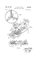
FIGURE 2 is an exploded perspective view showing a trowelling blade assembly that is a first embodiment of this invention,
FIGURE 3 is a sectional view, taken on the line 33 of FIGURE 2, and showing the manner in which the trowelling blade of FIGURE 2 is attached to its blade holder,
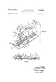
FIGURE 4 is a view similar to FIGURE 2 of a second embodiment, and
FIGURE 5 is a view similar to FIGURE 3, and taken on the line 55 of FIGURE 4.
Corresponding parts of all the figures of the drawing will be given the same reference number.
FIGURE 1 illustrates the general blade arrangement of a motor driven trowelling machine, wherein the three blades 10 are detachably connected to respective arms 11 of the machine, the arms being connected to a boss 12 that is mounted on the output shaft 13 of the machine, whereby the blades 10 can be rotated by the machine in a horizontal plane. The blades are mounted at equal angles of 120 (this angle would be for a four blade machine) and may be float blades which are used for general smoothing of a cement surface, finishing blades which are used to impart a very smooth finish to an already smoothed surface, or combination blades which are used for both purposes. A guard ring 14 is provided on the machine to protect the blades against contact with surrounding objects, e.g., walls and pillars, while the machine is in use.
Referring now especially to FIGURES 2 and 3, it will be seen that each blade 10 is generally rectangular as seen in plan having an upper surface 15, a working surface 16 disposed opposite to and therefore underneath the upper surface 15, two straight parallel longer sides 17 and two straight parallel shorter ends 18. The two end portions of the blade are inclined slightly upward to prevent the corners of the blades digging into the surface being smoothed as the machine is in use.
Attaching means for detachably connecting together the blade and the associated machine arm 11 comprise a first member 19 which in this embodiment is of generally U-shaped channel form, having the base 19a of the channel fastened to the upper surface 16 of the blade by suitable fastening devices 20, such as rivets, and the two spaced sides 19b of the channel extending generally perpendicular to the face 16. The channel member extends as nearly as possible the full length of the blade and is positioned centrally with respect to the sides 17 and ends 18 thereof, so that its longitudinal axis is generally parallel to the longer sides 17. Such a member is very rigid in relation to its weight, as compared with the fiat blade 10, and this rigidity is imparted to the blade 10, permitting the employment of thinner material for the blade than has been common hitherto. To this end also pairs of transversely spaced rivets 20 are employed, such a disposition making the blade assembly more rigid than if a single row of fastening devices are employed, as in the trowel devices used commercially hitherto.
The attaching means also comprise a second member 21 which is attached to the associated arm 11 by bolts 22, and serves as a supporting connection between the arm and the neighboring part of the guard ring 14. This member 21 is in this embodiment also of generally U-shaped channel form, having its base 21a fastened to the arm 11, and the two spaced longer sides 21b extending generally parallel to the longer sides 19b of the member 19. The ends of the channel are closed by respective shorter end walls 210. The relative dimensions of the two members 19 and 21 are such that with the two member attached together the member 19 is completely enclosed in a chamber constituted by the member 21 and the adjacent part of the blade 10, the side walls 21b and end walls 210 extending down as closely as possible to the adjacent part of the top surface 15 of the blade. The means for detachably attaching the two members together, which means will be described in greater detail below, are completely enclosed within this chamber and thereby protected from the deposit thereon of cement splatters and particles produced by operation of the machine.
The two members are detachably attached together in accordance with this invention by two longitudinally spaced pin and notch means. In this particular embodiment the first of these pin and notch means comprise a first pin 22 which is mounted in suitable apertures in the member 21, extending perpendicular to the side walls 21b,
and retained therein against endwise movement, for ex- 0 ample by heading. This first pin means 22 cooperates with associated first notch means, constituted by two spaced notches 23 in the adjacent end of the member 19, these notches extending longitudinally of the walls 1% and receiving the pin 22 for attaching engagement upon relative endwise movement of the two members.
The second pin attaching means comprise a second pin 24 mounted in suitable apertures in the member 19, eX- tending perpendicular to the side walls 191), and retained therein in a similar manner to the pin 22. The cooperating second slotted means is constituted by a single slot 25, provided in the head 26 of a bolt 27. The bolt shank has fiat flanks 27a, so that it is of noncircular cross-section, the shank extending through a correspondingly shaped hole in a blade spring member 28, an elongated slot 29 in the base 210 of the member 21, a correspondingly shaped hole in a cover member 30, and being threadedly engaged in a nut 31 that is adapted to be rotated by hand. The second slotted means constituted by the slot are thus capable of endwise movement relative to its associated member 21 for the required attaching engagement with, and disengagement from, the cooperating second pin 24.
The operation of attaching a trowel blade to the ma- 4 chine is illustrated generally by FIGURE 3 and is as follows:
The nut 31 is rotated to move the head 26 downwards under the downward bias of the bowed spring member 28,
rotation of the bolt being prevented by its engagement in the slot 29. The blade is moved endwise from the position shown in broken lines in FIGURE 3, in the direction of the arrow 32, until the slots 23 are attachably engaged with the pin 22; the blade is then rotated in the direction of the arrow 33 until it is fully home with the member 19 enclosed within the member 21; thereafter the assembly comprising the bolt 27, the nut 31 and the associated members 28 and 3d are moved together in the direction of the arrow 34 until the slot 25 is in attaching engagement with the pin 24; finally the nut 31 is rotated to tighten the engagement of the attaching means against the bias of the spring member 28, until the two members 19 and 21 are securely fastened together. The blade is removed by reversing the above-described sequence of operations.
The dimensions of the cover member 30 are such that with the bolt 26 in its endmost position, as illustrated by FIGURE 3, the member 30 completely covers the slot 29, and effectively prevents the entry of cement splatter, etc., to the interior of the compartment enclosing the fastening means.
In operation of the machine the leading edges of the blades are worn very much faster than the trailing edges, and the effective life of the blade can be increased if the fastening means permit the blade to be turned end-forend. In the blades in accordance with this invention this is accomplished by providing on the trowel member 19 a a suitably located further pin 35, constituting another second pin means for cooperation with the second slotted means, and two spaced slots 36 in the other end of the member, constituting another first slotted means for cooperation with the first pin means 22.
Referring now to FIGURES 4 and 5, the second embodiment illustrated therein has the same first member 19 and second member 21, and the same first pin means 22 and first slotted means 23 for detachably attaching the two members together. In this embodiment however a different arrangement of second pin and slotted means is provided, the second pin means being constituted by a single pin 37 mounted in the head 26 of the bolt 27 to extend transverscly of the members 19 and 21, parallel to the first pin 22, and the second slotted means being constituted by two spaced, generally T-shaped slots 38, the upright of the T of each slot opening at the free edge of the respective side wall, and the cross bar of the T extending oppositely towards the ends of the respective channel member 19.
In mounting the trowel blade on the machine, after engagement of the pin 22 and the slots 23, the assembly comprising the bolt 27 the pin 37 etc. are withdrawn until the pin can be inserted through the uprights of the two corresponding T shaped slots. Thereafter, with the two members 19 and 21 in close engagement, the assembly is moved in the direction of the arrow 34 to engage the pin 37 beneath the corresponding overhanging portions of the member 19. As with the first embodiment, another second slot means 39 is provided, corresponding to the second slot means 38, to permit the trowel blade to be turned end-for-end when required. It will be apparent that for the purposes of the present mvention the slots 38 and 39 could be of general L-shape with one leg opening to the free edges of the member 19 and the other leg extending towards the immediately adjacent end of the member. By the provision of T shape slots it is possible, if desired, to also use the trowel blade of the present invention in association with the fastening means specifically described and claimed in the copending application of Luigi Cagno, No. 405,552, filed October 21, 1964, and assigned to the same assignee.
It will be apparent to those skilled in the art that various changes and modifications may be made to the cmbodiments described, and other embodiments are possible, within the scope of the appended claims.
What we claim is:
1. A trowelling blade assembly for use with a trowelling machine, the assembly comprising a trowelling blade having an upper surface and a working surface opposite to said upper surface, andmeans for detachably attaching the blade to the trowelling machine, said attaching means comprising a first attachment member (19) secured to and upstandingfrom the upper surface of the blade, a cooperating second attachment member (21) of channel crosssection with an elongated slot (29) in the base wall thereof and with both of the channel ends closed, the channel being open towards the blade with its side and end walls extending into the close neighbourhood of the upper surface of the blade to constitute therewith an enclosure enclosing the first attachment member, a first set of two c0- operating attaching means (22, 23, 36) carried respectively by the said two attachment members and engaging one another within the said enclosure to detachably attach the members together, and a second set of cooperating attaching means (24, 25, 36 or 37, 33, 39) spaced from the first set, the second set comprising a fixed attaching means (24, or 38, 39) fixedly carried by the first attachment member and a movable attaching means (25 or 37) movably carried by the second attachment member, the last-mentioned two attaching means engaging one another within the said enclosure to detachably attach the attachment members together, the said movable attaching means comprising a movable screwthreaded member (27) mounted in the said slot for longitudinal movement in the direction of elongation thereof for engagement with and disengagement from the said fixed attaching means, and also mounted in the slot for movement towards and away from the blade for releasably locking the cooperating attaching means to one another, a nut (31) screw-threadably engaged with the screwthreaded member and producing the said releasable locking movement thereof upon rotation of the nut, and cover means movable with the screw-threaded member and closing the part of the slot not occupied by the lastmentioned member to prevent passage of material through the slot to the interior of the enclosure.
2. A trowelling blade assembly as claimed in claim 1, wherein the said movable attaching means comprise a slotted member (26) carried by the said screw-threaded member (27) and the cooperating fixed attaching means comprise a pin (24 or carried by the first attachment member, the slotted member having the slot (25) thereof lockably engaged with and disengaged from the pin by the said longitudinal and locking movements of the screw-threaded member, the pin being mounted by the first attachment member to extend transversely of the directions of said longitudinal and locking movements of the screw-threaded member.
3. A trowelling blade assembly as claimed in claim 1, wherein the said movable attaching means comprise a slotted member (26) carried by the said screw-threaded member (27) and the cooperating fixed attaching means comprise a pin (24 or 35) carried by the first attachment member, the slotted member having the slot (25) thereof lockably engaged with and disengaged from the pin by the said longitudinal and locking movements of the screwthreaded member, wherein the said first attachment member (19) is of channel section having two spaced sidewalls (19b) upstanding from the upper surface of the blade, and wherein the said pin (24 or 35) is mounted by and extends between the said spaced upstanding sidewalls.
4. A trowelling blade assembly as claimed in claim 1, wherein the-said movable attaching means comprise a pin member. (26, 37) carried by the said screw-threaded member (27 and the cooperating fixed attaching means comprise generally L-sha ed slot means (38, 39) carried by the first attachment member, thepin member having the pin (37) thereof lockably engaged with and disengaged from the slot means by the said longitudinal and locking movements of the screw-threaded member, the said slot means having a vertically extending entry portion and a horizontally extending portion connected to said entry portion, the pin being engaged in said horizontally extending portion for the said locking engagement with the slot means.
5. A trowellng blade assembly as claimed in claim 1, wherein the said movable attaching means comprise a pin member 2s, 37) carried by the said screw-threaded member (27) and the cooperating fixer attaching means comprise generally L-shaped slot means (38, 39) carried by the first attachment member, the pin member having the pin thereof lockably engaged with and disengaged from the slot means by the said longitudinal and locking movements of the screw-threaded member, wherein the said first attachment member (15 is of channel section having two spaced sidewalls (19b) upstanding from the upper surface of the blade, and wherein the said slot means comprise respective parallel slots in the respective channel sidewalls, each slot having a vertically extending entry portion and a horizontally-extending portion connected to said entry portion, the pin being engaged in the horizontally extending portion for the said locking engagement with the slots.
6. A trowelling blade assembly as claimed in claim 1, wherein the two attaching means (22 and 23, 36) of the said first set are fixedly carried by their respective attachment members, and are attachably engaged with and detached from one another by movement relative to one another of the two attachment members.
7. A trowelling blade assembly as claimed in claim 1, wherein the attaching means of the first set comprise a pin member (22) fixedly carried by the second attachment member (21) and the first attachment member (19) is provided with end slots (23, 36) at the two opposite ends thereof, the said end slots being selectively engageable with the last-mentioned pin member (22) to permit reversal of the blade end-for-end, and wherein the attaching means of the second set comprise a pair of spaced pins (24, 35) fixedly carried by the first attachment member (19) and each constituting a respective fixed attachment means, and a movable slotted member (25, 26) carried by the said screw-threaded member (27) and selectively engageable with a corresponding one of th last-mentioned pin means (24, 35) when the blade is reversed end-for-end.
8. A trowelling blade assembly as claimed in claim 1, wherein the attaching means of the first set comprise a pin member (22) fixedly carried by the second attachment member (21) and the first attachment member (19) is provided with end slots (23, 36) at the two opposite ends thereof, the said end slots being selectively engageable with the last-mentioned pin member to permit reversal of the blade end-for-end, and wherein the attaching means of the second set comprise a pair of spaced slot means (38, 39) fixedly carried by the first attachment member (19) and each constituting a respective fixed attachment means, and a movable pin member (26, 37) carried by the said screw-threaded member (27 and selectively engageable with a corresponding one of the said slot means (38, 39) when the blade is reversed endfor-end.
9. A trowelling blade assembly for use with a trowelling machine, the assembly comprising a trowelling blade having an upper surface and a work-ing surface opposite to said upper surface, and means for detachably attaching the blade to the trowelling machine, said attaching means comprising a first attachment member (19) secured to and upstanding from the upper surface of the blade, a cooperating second attachment member (21) for attach ment to the trowelling machine, a first set of two cooperating attaching means (22, 23, 36) carried respectively by the said two attachment members and engaging one another to detachably attach the members together, and a second set of cooperating attaching means (24, 25, 36 or 37, 38, 39) spaced from the first set, the second set comprising a fixed attaching means (24, 25 or 38, 39) fixedly carried by the first attachment member and a movable attaching means (25 or 37) movably carried by the second attachment member, the last-mentioned two attaching means engaging one another to detachably attach the attachment members together, the said movable attaching means comprising a movable member (27) mounted by the second attachment member for longitudinal movement for engagement with and disengagement from the said fixed attaching means, and also mounted thereby for movement towards and away from the blade for releasably locking the cooperating attaching means to one another, and moving and locking means (31) operatively engaged with the movable member for producing the said longitudinal and releasable locking movements thereof.
10. A trowelling blade assembly for use with a trowelling machine, the assembly comprising a trowelling blade having an upper surface and a working surface opposite to said upper surface, and means for detachably attaching the blade to the trowelling machine, said attaching means comprising a first attachment member (19) secured to and upstanding from the upper surface of the blade, 21 cooperating second attachment member (21) for attachment to the trowelling machine, a first set of two cooperating attaching means (22, 23, 36) carried respectively by the said two attachment members and engaging one another to detachably attach the members together, and a second set of cooperating attaching means (24, 25, 36 or 37, 38, 39) spaced from the first set, the second set comprising a fixed attaching means (24, 25 or 38, 39) fixedly carried by the first attachment member and a movable attaching means (25 or 37) movably carried by the second attachment member, the last-mentioned two attaching means engaging one another to detachably attach the attachment members together, the said movable attaching means comprising a movable screw-threaded member (27) mounted by the second attachment member for longitudinal movement for engagement with and disengagement from the said fixed attaching means, and also mounted thereby for vertical movement for releasably locking the cooperating attaching means to one another, and nut means (31) screw-threadably engaged with the screw-threaded member and producing the said releasable locking movement upon rotation thereof.
11. A trowelling blade assembly as claimed in claim 10, wherein the said movable attaching means comprise a slotted member (26) carried by the said screw-threaded member (27) and the cooperating fixed attaching means comprise a pin (24 or 35) carried by the first attachment member, the slotted member having the slot (25) thereof lockably engaged with and disengaged from the pin by the said longitudinal and locking movements of the screwthreaded member, the pin being mounted by the first attachment member to extend transversely of the directions of said longitudinal and locking movements of the screw-threaded member.
12. A trowelling blade assembly as claimed in claim 10, wherein the said movable attaching means comprise a slotted member (26) carried by the said screw-threaded member (27 and the cooperating fixed attaching means comprise a pin (24 or 35) carried by the first attachment member, the slotted member having the slot (25) thereof lockably engaged with and disengaged from the pin by the said longitudinal and locking movements of the screwthreaded member, wherein the said first attachment member (19) is of channel section having two spaced sidewalls (19b) upstanding from the upper surface of the blade, and wherein the said pin (24 or 35) is mounted by and extends between the said spaced upstanding sidewalls.
13. A trowelling blade assembly as claimed in claim 10 wherein the said movable attaching means comprises a pin member (26, 37) carried by the said screw-threaded member (27) and the cooperating fixed attaching means comprise generally L-shaped slot means (38, 39) carried by the first attachment member, the pin member having the pin (37) thereof lockably engaged with and disengaged from the slot means by the said longitudinal and locking movements of the screw-threaded member, the said slot means having a vertically/extending entry portion and a horizontally/extending portion connected to said entry portion, the pin being engaged in said horizontally extending portion for the said locking engagement with the slot means.
14. A trowelling blade assembly as claimed in claim 10, wherein the said movable attaching means comprise a pin member (26, 37 carried by the said screw-threaded member (27) and the cooperating fixed attaching means comprise generally L-shaped slot means (38, 39) carried by the first attachment member, the pin member having the pin thereof lockably engaged with and disengaged from the slot means by the said longitudinal and locking movements of the screw-threaded member, wherein the said first attachment member (19) is of channel section having two spaced sidewalls (19b) upstanding from the upper surface of the blade, and wherein the said slot means comprise respective parallel slots in the respective channel sidewalls, each slot having a vertically/extending entry portion and a horizontally/extending portion connected to said entry portion, the pin being engaged in the horizontally/extending portion for the said locking engagement with the slots.
15. A trowelling blade assembly as claimed in claim 10, wherein the two attaching means (22 and 23, 36) of the said first set are fixedly carried by their respective attachment members, and are attachably engaged with and detached from one another by movement relative to one another of the two attachment members.
16. A trowelling blade assembly as claimed in claim 10, wherein the attaching means of the first set comprise a pin member (22) fixedly carried by the second attachment member (21) and the first attachment member (19) is provided with end slots (23, 36) at the two opposite ends thereof, the said end slots being selectively engageable with the last-mentioned pin member (22) to permit reversal of the blade end-for-end, and wherein the attaching means of the second set comprise a pair of spaced pins (24, 35) fixedly carried by the first attachment member (19) and each constituting a respective fixed attachment means, and a movable slotted member (25, 26) carried by the said screw-threaded member (27) and selectively engageable with a corresponding one of the last-mentioned pin means (24, 35 when the blade is reversed end-for-end.
17. A trowelling blade assembly as claimed in claim 10, wherein the attaching means of the first set comprise a pin member (22) fixedly carried by the second attachment member (21) and the first attachment member (19) is provided with end slots (23, 36) at the two opposite ends thereof, the said end slots being selectively engageable with the last-menioned pin member to permit reversal of the blade end-for-end, and wherein the attaching means of the second set comprise a pair of spaced slot means (38, 39) fixedly carried by the first attachment member (19) and each constituting a respective fixed attachment means, and a movable pin member (26, 37) carried by the said screw-threaded member (27) and selectively engageable with a corresponding one of the said slot means (38, 39) when the blade is reversed end-for end.
References Cited UNITED STATES PATENTS 3,296,946 1/1967 Cagno 94-45 3,066,332 12/1962 Sedlacek l4--27 JACOB L. NACKENOFF, Primary Examiner.
Priority Applications (5)
| Application Number | Priority Date | Filing Date | Title |
|---|---|---|---|
| US502683A US3402647A (en) | 1965-10-22 | 1965-10-22 | Trowelling blade assemblies |
| FR80945A FR1506439A (en) | 1965-10-22 | 1966-10-21 | blade assembly for machine for spreading or smoothing a material such as cement |
| GB47317/66A GB1156505A (en) | 1965-10-22 | 1966-10-21 | Trowelling Blade Assemblies |
| DE19661659645 DE1659645A1 (en) | 1965-10-22 | 1966-10-21 | Glaett machine with a glaett or coating blade arrangement |
| BE707414D BE707414A (en) | 1965-10-22 | 1967-12-01 |
Applications Claiming Priority (1)
| Application Number | Priority Date | Filing Date | Title |
|---|---|---|---|
| US502683A US3402647A (en) | 1965-10-22 | 1965-10-22 | Trowelling blade assemblies |
Publications (1)
| Publication Number | Publication Date |
|---|---|
| US3402647A true US3402647A (en) | 1968-09-24 |
Family
ID=23998911
Family Applications (1)
| Application Number | Title | Priority Date | Filing Date |
|---|---|---|---|
| US502683A Expired - Lifetime US3402647A (en) | 1965-10-22 | 1965-10-22 | Trowelling blade assemblies |
Country Status (4)
| Country | Link |
|---|---|
| US (1) | US3402647A (en) |
| DE (1) | DE1659645A1 (en) |
| FR (1) | FR1506439A (en) |
| GB (1) | GB1156505A (en) |
Cited By (11)
| Publication number | Priority date | Publication date | Assignee | Title |
|---|---|---|---|---|
| US3675544A (en) * | 1970-12-22 | 1972-07-11 | Francesco Zochil | Quick coupler assembly |
| US3732590A (en) * | 1970-06-03 | 1973-05-15 | E Horst | Sweeper |
| US4046483A (en) * | 1976-11-18 | 1977-09-06 | Sutherland John W | Troweling machine |
| US4320986A (en) * | 1980-03-21 | 1982-03-23 | Morrison Donald R | Motor powered rotary trowel |
| US4388017A (en) * | 1981-11-27 | 1983-06-14 | Morrison Donald R | Troweling blade rotor assembly |
| US5372452A (en) * | 1993-02-24 | 1994-12-13 | Hodgson; James A. | Power trowels |
| EP1158115A1 (en) * | 2000-05-24 | 2001-11-28 | B-MAC, besloten vennootschap met beperkte aansprakelijkheid | Finishing device for floors and blade used therewith |
| US20080025794A1 (en) * | 2006-07-27 | 2008-01-31 | Lauro Barcenas | Power trowel attachment for a drill |
| US11142875B2 (en) * | 2019-12-19 | 2021-10-12 | John Wade Lightfoot | Vibrating float tool |
| US20220268035A1 (en) * | 2021-02-24 | 2022-08-25 | Milwaukee Electric Tool Corporation | Concrete trowel |
| US12442202B2 (en) | 2021-02-24 | 2025-10-14 | Milwaukee Electric Tool Corporation | Concrete trowel |
Citations (2)
| Publication number | Priority date | Publication date | Assignee | Title |
|---|---|---|---|---|
| US3066332A (en) * | 1958-05-24 | 1962-12-04 | Beteiligungs & Patentverw Gmbh | Detachable bridge |
| US3296946A (en) * | 1964-10-21 | 1967-01-10 | Hamilton Float & Trowel Ltd | Trowelling blade assemblies |
-
1965
- 1965-10-22 US US502683A patent/US3402647A/en not_active Expired - Lifetime
-
1966
- 1966-10-21 FR FR80945A patent/FR1506439A/en not_active Expired
- 1966-10-21 DE DE19661659645 patent/DE1659645A1/en active Pending
- 1966-10-21 GB GB47317/66A patent/GB1156505A/en not_active Expired
Patent Citations (2)
| Publication number | Priority date | Publication date | Assignee | Title |
|---|---|---|---|---|
| US3066332A (en) * | 1958-05-24 | 1962-12-04 | Beteiligungs & Patentverw Gmbh | Detachable bridge |
| US3296946A (en) * | 1964-10-21 | 1967-01-10 | Hamilton Float & Trowel Ltd | Trowelling blade assemblies |
Cited By (16)
| Publication number | Priority date | Publication date | Assignee | Title |
|---|---|---|---|---|
| US3732590A (en) * | 1970-06-03 | 1973-05-15 | E Horst | Sweeper |
| US3675544A (en) * | 1970-12-22 | 1972-07-11 | Francesco Zochil | Quick coupler assembly |
| US4046483A (en) * | 1976-11-18 | 1977-09-06 | Sutherland John W | Troweling machine |
| US4320986A (en) * | 1980-03-21 | 1982-03-23 | Morrison Donald R | Motor powered rotary trowel |
| US4388017A (en) * | 1981-11-27 | 1983-06-14 | Morrison Donald R | Troweling blade rotor assembly |
| US5372452A (en) * | 1993-02-24 | 1994-12-13 | Hodgson; James A. | Power trowels |
| US6536989B2 (en) | 2000-05-24 | 2003-03-25 | B-Mac, Besloten Vennootschap Met Beperkte Aansprakelljkheld | Finishing device for floors made of hardenable material and blade used therewith |
| BE1013536A3 (en) * | 2000-05-24 | 2002-03-05 | B Mac Bv Met Beperkte Aansprak | Finisher FLOORS FOR HARD MATERIALS AND THUS CAN BE USED SHEET. |
| EP1158115A1 (en) * | 2000-05-24 | 2001-11-28 | B-MAC, besloten vennootschap met beperkte aansprakelijkheid | Finishing device for floors and blade used therewith |
| US20080025794A1 (en) * | 2006-07-27 | 2008-01-31 | Lauro Barcenas | Power trowel attachment for a drill |
| US7399140B2 (en) * | 2006-07-27 | 2008-07-15 | Lauro Barcenas | Power trowel attachment for a drill |
| US11142875B2 (en) * | 2019-12-19 | 2021-10-12 | John Wade Lightfoot | Vibrating float tool |
| US20220268035A1 (en) * | 2021-02-24 | 2022-08-25 | Milwaukee Electric Tool Corporation | Concrete trowel |
| US11927022B2 (en) * | 2021-02-24 | 2024-03-12 | Milwaukee Electric Tool Corporation | Concrete trowel |
| US12241266B2 (en) | 2021-02-24 | 2025-03-04 | Milwaukee Electric Tool Corporation | Concrete trowel |
| US12442202B2 (en) | 2021-02-24 | 2025-10-14 | Milwaukee Electric Tool Corporation | Concrete trowel |
Also Published As
| Publication number | Publication date |
|---|---|
| GB1156505A (en) | 1969-06-25 |
| FR1506439A (en) | 1967-12-22 |
| DE1659645A1 (en) | 1969-09-18 |
Similar Documents
| Publication | Publication Date | Title |
|---|---|---|
| US3402647A (en) | Trowelling blade assemblies | |
| US3296946A (en) | Trowelling blade assemblies | |
| DE219406T1 (en) | MICROWAVE OVEN WITH INTERCHANGEABLE EQUIPMENT AND ACCESSORIES FOR THIS OVEN. | |
| DE69810996T2 (en) | Vacuum cleaner nozzle for upholstery material | |
| JPH0368805B2 (en) | ||
| EP0071075B1 (en) | Canal constructing apparatus comprising a leveling or a covering installation | |
| SE511044C2 (en) | A grating cleaning device | |
| US1032081A (en) | Ice-breaker. | |
| US4925341A (en) | Replaceable cement-trowel blade trailing edge | |
| US2930065A (en) | Scraper attachment for power tool | |
| US931483A (en) | Grinder-head. | |
| DE1041386B (en) | Motor-driven device, in particular for cleaning meatloaf | |
| US519629A (en) | Manure-pulverizer | |
| CN109848458A (en) | A kind of universal structure radial drilling machine of electromechanical automation processing | |
| US1791712A (en) | Crushing machinery | |
| DE3825377A1 (en) | WASHING DRUM | |
| DE102019125053A1 (en) | Household appliance, preferably vacuum cleaner, particularly preferably hand-held vacuum cleaner | |
| DE1584416A1 (en) | Shovel holder in a mixer for concrete or similar building materials | |
| US3675544A (en) | Quick coupler assembly | |
| DE202022003276U1 (en) | wallpaper scraper | |
| CN219586278U (en) | Card clothing removing device of carding machine cover plate and carding machine | |
| US964103A (en) | Dabbing-brush. | |
| US1249026A (en) | Block-leveler. | |
| DE848084C (en) | Dishwasher | |
| US940488A (en) | Rabble-arm and rake. |