US3402643A - Piston having pin bore relief and method of manufacture - Google Patents
Piston having pin bore relief and method of manufacture Download PDFInfo
- Publication number
- US3402643A US3402643A US558330A US55833066A US3402643A US 3402643 A US3402643 A US 3402643A US 558330 A US558330 A US 558330A US 55833066 A US55833066 A US 55833066A US 3402643 A US3402643 A US 3402643A
- Authority
- US
- United States
- Prior art keywords
- bore
- piston
- pin
- skirt
- sides
- Prior art date
- Legal status (The legal status is an assumption and is not a legal conclusion. Google has not performed a legal analysis and makes no representation as to the accuracy of the status listed.)
- Expired - Lifetime
Links
Images
Classifications
-
- F—MECHANICAL ENGINEERING; LIGHTING; HEATING; WEAPONS; BLASTING
- F16—ENGINEERING ELEMENTS AND UNITS; GENERAL MEASURES FOR PRODUCING AND MAINTAINING EFFECTIVE FUNCTIONING OF MACHINES OR INSTALLATIONS; THERMAL INSULATION IN GENERAL
- F16J—PISTONS; CYLINDERS; SEALINGS
- F16J1/00—Pistons; Trunk pistons; Plungers
- F16J1/10—Connection to driving members
- F16J1/14—Connection to driving members with connecting-rods, i.e. pivotal connections
- F16J1/16—Connection to driving members with connecting-rods, i.e. pivotal connections with gudgeon-pin; Gudgeon-pins
-
- Y—GENERAL TAGGING OF NEW TECHNOLOGICAL DEVELOPMENTS; GENERAL TAGGING OF CROSS-SECTIONAL TECHNOLOGIES SPANNING OVER SEVERAL SECTIONS OF THE IPC; TECHNICAL SUBJECTS COVERED BY FORMER USPC CROSS-REFERENCE ART COLLECTIONS [XRACs] AND DIGESTS
- Y10—TECHNICAL SUBJECTS COVERED BY FORMER USPC
- Y10T—TECHNICAL SUBJECTS COVERED BY FORMER US CLASSIFICATION
- Y10T29/00—Metal working
- Y10T29/49—Method of mechanical manufacture
- Y10T29/49229—Prime mover or fluid pump making
- Y10T29/49249—Piston making
- Y10T29/49256—Piston making with assembly or composite article making
Definitions
- a head and a skirt 12 thereon are integrally joinedby an internal pair of mutually confronting, longitudinally extending piston struts 14 therebetween.
- the relation of the several views in the drawing is indicated by various section lines.
- the head has a gasloaded face 16 recessed according to conventional construction in piston engines.
- a transversely disposed wrist pin bore 18 is located in the narrow pin boss portions 20 of the individual struts 14.
- the bore 18 accepts a hollow wrist pin 22 of circular cross-section which is between and engages two snap rings 24 provided in opposite ends of the bore and which pivot'ally secures the piston to the outer end of a crankshaft-connectedconnecting rod 26.
- the wrist pin connection is a vulnerable point in the piston because of the-cracking problem hereinafter described.
- the system of forces accommodated through that connection consists of the longitudinal gas force exerted in the direction of movement of the piston, the reaction force of the connecting rod 26 which is at a constantly varying angle generally opposing the gas force, and the reaction of the cylinder wall, not shown, on both the thrust and antithrust sides of the piston in a direc tion perpendicular to piston movement.
- the wrist pin 22 conventionally made of tubular steel, deflects among other ways in the portions intermediate its ends so as to oval, or more technically take an elliptical shape in cross-section, under maximum gas loadings on the piston. That is to say, there is perceptible local flattening of the wrist pin 22 in a direction perpendicular to piston movement, all in a manner more particularly described in Cook et al. US. Patent No. 3,357,318, which is assigned to the assignee of the present application and the disclosure of which is incorporated in entirety herein by reference.
- the piston is preferably a die-casting of aluminum or an alloy thereof, with the struts 14 being cast to final size and the bore formed by a core, not shown, present in the dies during casting.
- No bearing insert is essential in the final piston because, as part of the last tool operations enlarging the bore, the bore surface can be worked by a turning arbor, not shown, carrying a set of rotatably mounted, work-hardening rollers about its periphery.
- the crystalline structure of the bore is thus work hardened to a depth of several thousandths of an inch, or slightly more, due to pressure of the rollers which rotate as they are being revolved about the arbor axis.
- the contact pressures are not excessive but the rolling is nevertheless effective to work-harden aluminum.
- the foregoing operation can be performed with good results after the cored-in bore 18 has been finish machined.
- the work hardening is deliberately not strenuous, because of the possibility that the bore would become out of round or lose the accuracy of its finished dimension.
- the work hardening operation is a little more rigorous and penetrates for slightly more than several thousands of an inch in depth within the worked metal of the boss portions 20. Thereafter, the bore 144 is finish machined, the cutting or honing being shallow, e.g., to a depth of only one or two or three thousandths of an inch so as not to machine away the entire work hardened metal.
- each bore boss portion at the skirt sides thereof Due to the narrow shape of each bore boss portion at the skirt sides thereof, the coring of the bore leaves the side dimensions at 36 and the bore dimensions at 38 having outlines indicated by broken lines.
- the last tool operation be it final machining step or the work hardening step if employed, cuts through the skirt sides of the bore portion to leave the final outline of intersection as shown in solid lines 40.
- pin bore relief is an inherency of the last tool operation, which saves the manufacturer from the necessary relief step or steps in comparable procedures.
- the skirt itself on the skirt sides of the wrist pin and bore provides an adequate uninterrupted surface for transmitting piston side thrust to the engine cylinder walls.
- the wrist pin stays essentially circular in crosssection, and the ellipticalness principally occurs only in the vicinity of the platen 28 of the inner end of the bore boss portion.
- the piston cracking problem is materially alleviated in the present piston, such undesired cracks normally appearing as longitudinally extending cracks in regular pistons beginning on the head side of the bore at 42 (FIGURE 1).
- the intersection 40 of the bore with each boss portion at the skirt side defines a semicircular are (technically, an ellipse), with the outer end of the relief falling at no more than approximately half way to the outer end of the bore.
- the relief falls slightly short of the inside corner of the strut and the skirt indicated at 44.
- Piston comprising:
- said pin having skirt sides spaced 90 from both the side thereof adjacent the head and the side of the pin opposite the piston head;
- pin boss portions of said struts being no wider than approximately the pin diameter adjacent to the skirt sides of the pin, such that said pin boss portions adjacent to the skirt sides of the pin are not of appreciable thickness and local outward expansion of the pin as a result of temporary pin flattening by gas loads will not be significantly opposed by the boss walls.
- said bore cutting completely through the boss side walls, and forming a path of intersection between the bore walls and the boss side walls falling for at least a portion between the inner ends of the boss portions and the piston skirt;
- said pin being essentially in circular shape in cross section, and retaining such a shape in the vicinity of the skirt and being flattened from such shape in the vicinity of the inner ends of the boss portions when said piston is subjected to axial gas loads.
- said path of intersection having approximately an elliptical form, inside of which the wrist pin is exposed by the bore.
- a piston for use in a reciprocating engine and having struts and a head and a skirt joined by the struts, the piston having a bore in the struts transversely disposed therein and having the piston head at one side of the bore spaced 90 from the skirt sides of such bore:
- a strut part having generally longitudinally extending sides including an inner face and opposite lateral sides (34) each making a dihedral angle with the inner face, said lateral sides being tapered so as to converge at least in one direction;
- the invention of claim 15 characterized by the converging sides of the strut part being cast with a twoway taper so as to converge both in the direction of the inner face and in a longitudinal direction of the part.
Landscapes
- Engineering & Computer Science (AREA)
- General Engineering & Computer Science (AREA)
- Chemical & Material Sciences (AREA)
- Combustion & Propulsion (AREA)
- Mechanical Engineering (AREA)
- Pistons, Piston Rings, And Cylinders (AREA)
Description
Sept. 24, 1968 G. J. MAAT 3,402,643
PISTON HAVING PIN BORE RELIEF AND METHOD OF MANUFACTURE Filed June 17, 1966 .Zizz/nor: Gear e cf Maat w 49 4am United States Patent ()flice 3,402,643 Patented Sept. 24, 1968 3,402,643 PISTON HAVING PIN BORE RELIEF AND METHOD OF MANUFACTURE George J. Maat,"Bat.'avia,Ill., assignor to International Harvester Company, Chicago, III., a corporation of Delaware r Filed June 17, 1966, Ser. No. 558,330
; 16 Claims. (Cl. 92-187) ABSTRACT OF THE DISCLOSURE Piston cast with narrow struts such that, when the wrist pin bore is formed to its final size transversely through the struts and skirt of the piston, the bore walls forming the skirt sides of the bore are left with no appreciable thickness, i.e., the bore walls are either thin or, if present at all, they amount to no more than partial walls at the skirt sides of the bore.
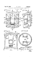
In -apiston having pin bore relief as shown in the accompanying drawing, a head and a skirt 12 thereon are integrally joinedby an internal pair of mutually confronting, longitudinally extending piston struts 14 therebetween. The relation of the several views in the drawing is indicated by various section lines. The head has a gasloaded face 16 recessed according to conventional construction in piston engines.
A transversely disposed wrist pin bore 18 is located in the narrow pin boss portions 20 of the individual struts 14. The bore 18 accepts a hollow wrist pin 22 of circular cross-section which is between and engages two snap rings 24 provided in opposite ends of the bore and which pivot'ally secures the piston to the outer end of a crankshaft-connectedconnecting rod 26.
The wrist pin connection is a vulnerable point in the piston because of the-cracking problem hereinafter described. The system of forces accommodated through that connection consists of the longitudinal gas force exerted in the direction of movement of the piston, the reaction force of the connecting rod 26 which is at a constantly varying angle generally opposing the gas force, and the reaction of the cylinder wall, not shown, on both the thrust and antithrust sides of the piston in a direc tion perpendicular to piston movement.
The wrist pin 22, conventionally made of tubular steel, deflects among other ways in the portions intermediate its ends so as to oval, or more technically take an elliptical shape in cross-section, under maximum gas loadings on the piston. That is to say, there is perceptible local flattening of the wrist pin 22 in a direction perpendicular to piston movement, all in a manner more particularly described in Cook et al. US. Patent No. 3,357,318, which is assigned to the assignee of the present application and the disclosure of which is incorporated in entirety herein by reference.
The conventional aspects of the piston are apparent. The emphasis herein is on the particular structure of the struts 14, each bounded on the exposed surfaces by an end face or plane 28 at the inner end of the boss portion, an obliquely disposed strut end wall 30 intersecting said plane and being at the bottom of the strut, an upper inner wall 32 of the strut intersecting said plane, and lateral sides or walls 34 which are on the skirt sides of the bore 18 and which, in the vicinity of the boss portion 20, either disappear completely or are relieved enough to render them walls of no appreciable thickness. The referred to local flattening of the pin 22 is encountered by the walls 34. But these boss walls as indicated are of only slight thickness at most and are incapable of transmitting suflicient stress to oval the bore to the point that the crystalline structure in the metal surface on the head side of the bore is placed under cracking-producing tension stress.
The piston is preferably a die-casting of aluminum or an alloy thereof, with the struts 14 being cast to final size and the bore formed by a core, not shown, present in the dies during casting. No bearing insert is essential in the final piston because, as part of the last tool operations enlarging the bore, the bore surface can be worked by a turning arbor, not shown, carrying a set of rotatably mounted, work-hardening rollers about its periphery.
The crystalline structure of the bore is thus work hardened to a depth of several thousandths of an inch, or slightly more, due to pressure of the rollers which rotate as they are being revolved about the arbor axis. The contact pressures are not excessive but the rolling is nevertheless effective to work-harden aluminum.
The foregoing operation can be performed with good results after the cored-in bore 18 has been finish machined. The work hardening is deliberately not strenuous, because of the possibility that the bore would become out of round or lose the accuracy of its finished dimension.
In case the wrist pin bore 14 is rough machined but not finish machined prior to hardening, the work hardening operation is a little more rigorous and penetrates for slightly more than several thousands of an inch in depth within the worked metal of the boss portions 20. Thereafter, the bore 144 is finish machined, the cutting or honing being shallow, e.g., to a depth of only one or two or three thousandths of an inch so as not to machine away the entire work hardened metal.
Due to the narrow shape of each bore boss portion at the skirt sides thereof, the coring of the bore leaves the side dimensions at 36 and the bore dimensions at 38 having outlines indicated by broken lines. The last tool operation, be it final machining step or the work hardening step if employed, cuts through the skirt sides of the bore portion to leave the final outline of intersection as shown in solid lines 40. Hence, pin bore relief is an inherency of the last tool operation, which saves the manufacturer from the necessary relief step or steps in comparable procedures. This work saving aspect obviating metal removal in difficult places is one of the primary features of my invention.
The skirt itself on the skirt sides of the wrist pin and bore provides an adequate uninterrupted surface for transmitting piston side thrust to the engine cylinder walls. Immediately on the inner side of each pin retaining snap ring 24, the wrist pin stays essentially circular in crosssection, and the ellipticalness principally occurs only in the vicinity of the platen 28 of the inner end of the bore boss portion.
The piston cracking problem is materially alleviated in the present piston, such undesired cracks normally appearing as longitudinally extending cracks in regular pistons beginning on the head side of the bore at 42 (FIGURE 1). The intersection 40 of the bore with each boss portion at the skirt side defines a semicircular are (technically, an ellipse), with the outer end of the relief falling at no more than approximately half way to the outer end of the bore. Preferably, the relief falls slightly short of the inside corner of the strut and the skirt indicated at 44.
There is a minor inward taper, not shown, of the struts so that at their skirt sides the opposite walls 34 converge slightly inwardly toward the center of the piston. The same walls 34 also have a slight convergence downwardly, i.e., they taper away from the head of the piston.
7 I claim:
1. Piston comprising:
a head having a gas-loaded face;
a skirt;
longitudinally extending struts in the piston joined between the head and skirt and having bored pin boss portions (20); and
a hollow wrist pin in the bore of the pin boss portions,
said pin having skirt sides spaced 90 from both the side thereof adjacent the head and the side of the pin opposite the piston head;
at least the pin boss portions of said struts being no wider than approximately the pin diameter adjacent to the skirt sides of the pin, such that said pin boss portions adjacent to the skirt sides of the pin are not of appreciable thickness and local outward expansion of the pin as a result of temporary pin flattening by gas loads will not be significantly opposed by the boss walls.
2. The invention of claim 1 characterized by:
said bore cutting completely through the boss side walls, and forming a path of intersection between the bore walls and the boss side walls falling for at least a portion between the inner ends of the boss portions and the piston skirt;
said pin being essentially in circular shape in cross section, and retaining such a shape in the vicinity of the skirt and being flattened from such shape in the vicinity of the inner ends of the boss portions when said piston is subjected to axial gas loads.
3. The invention of claim 2 characterized by:
said path of intersection (40) falling approximately at the inside corners (44) between the pin boss portions and the skirt.
4. The invention of claim 3 characterized by:
said path of intersection having approximately an elliptical form, inside of which the wrist pin is exposed by the bore.
5. In a piston for use in a reciprocating engine and having struts and a head and a skirt joined by the struts, the piston having a bore in the struts transversely disposed therein and having the piston head at one side of the bore spaced 90 from the skirt sides of such bore:
the improvement wherein the bored portions of said struts are no wider than approximately the bore diameter adjacent to the skirt sides of the bore such that the bore walls forming the skirt sides of the bore are not of appreciable thickness.
6. The invention of claim 5, characterized by the bore cutting through the sides of the struts adjacent to the skirt sides of the bore.
7. The invention of claim 6, characterized by the path of intersection between the bore walls and the strut sides being generally a semicircular arc.
8. The invention of claim 7, said are being coexten sive in length with at least a major part of the bored portions of the struts.
9. The invention of claim 5, characterized by the struts being cast to final size and the bore being cored-in to initial size.
10. The method, in piston manufacture; of fo'rining a piston pin bore so as to provide relief in the skirt sides of bore boss portions of a piston, said piston having a head and a skirt joined bysaid portions, the head side of the bore being spaced from the skirt sides of the bore, said method comprising:
casting the piston with a cored-in pin bore in the boss portions; and 1 enlarging the bore such that said bore boss portions on their skirt sides are no wider than approximately the bore diameter and the skirt sides of the bore are not of appreciable thickness.
11. The invention of claim 10, characterized by enlarging the bore such that at least part of the boss portions on their skirt sides are no wider than the cored-in bore diameter.
12. The invention of claim 10, characterized by: I
work hardening the bore and finally machining the bore. I
13. The invention of claim 10, characterized by casting bore boss portions to final size at the time of casting the cored-in pin bore.
14. The manufacture of a cross bored strut part having walls of no appreciable thickness at the lateral sides of the bore, comprising:
a strut part having generally longitudinally extending sides including an inner face and opposite lateral sides (34) each making a dihedral angle with the inner face, said lateral sides being tapered so as to converge at least in one direction; and
a cross bore (18) in the strut in a direction transverse to and passing through the inner face thereof, and cut at least partly through the converging sides of the strut part.
15. The invention of claim 14, the provision of th strut part and the bore formation being cast.
16. The invention of claim 15, characterized by the converging sides of the strut part being cast with a twoway taper so as to converge both in the direction of the inner face and in a longitudinal direction of the part.
References Cited UNITED STATES PATENTS 1,959,279 5/1934 Stearns 92187 X 2,483,674 10/1949 Rosen 92187 X 2,387,634 10/1945 Anderson 92187 2,780,505 2/1957 Venner 29l56.5 X 2,990,226 6/1961 Fangman 92187 3,305,918 2/1967 Christen et a1 29156.5 3,324,772 6/1967 Whittstock 92222 3,357,318 12/1967 Packard 92187 FOREIGN PATENTS 198,068 6/1958 Austria.
MARTIN P. SCHWADRON, Primary Examiner.
G, N. BAUM, Assistant Examiner.
Priority Applications (1)
| Application Number | Priority Date | Filing Date | Title |
|---|---|---|---|
| US558330A US3402643A (en) | 1966-06-17 | 1966-06-17 | Piston having pin bore relief and method of manufacture |
Applications Claiming Priority (1)
| Application Number | Priority Date | Filing Date | Title |
|---|---|---|---|
| US558330A US3402643A (en) | 1966-06-17 | 1966-06-17 | Piston having pin bore relief and method of manufacture |
Publications (1)
| Publication Number | Publication Date |
|---|---|
| US3402643A true US3402643A (en) | 1968-09-24 |
Family
ID=24229124
Family Applications (1)
| Application Number | Title | Priority Date | Filing Date |
|---|---|---|---|
| US558330A Expired - Lifetime US3402643A (en) | 1966-06-17 | 1966-06-17 | Piston having pin bore relief and method of manufacture |
Country Status (1)
| Country | Link |
|---|---|
| US (1) | US3402643A (en) |
Cited By (4)
| Publication number | Priority date | Publication date | Assignee | Title |
|---|---|---|---|---|
| US3564978A (en) * | 1968-12-03 | 1971-02-23 | Gen Motors Corp | Piston and connecting rod |
| DE3211472C1 (en) * | 1982-03-29 | 1983-03-10 | Mahle Gmbh, 7000 Stuttgart | Plunger pistons for internal combustion engines with means for laterally guiding the connecting rod in the piston |
| DE3342528C1 (en) * | 1983-11-24 | 1985-02-07 | Alcan Aluminiumwerk Nürnberg GmbH, 6000 Frankfurt | Pistons for internal combustion engines and / or for compressors or connecting rods for this |
| DE102005061898A1 (en) * | 2005-12-23 | 2007-06-28 | Mahle International Gmbh | Piston connecting rod assembly for an internal combustion engine |
Citations (9)
| Publication number | Priority date | Publication date | Assignee | Title |
|---|---|---|---|---|
| US1959279A (en) * | 1932-10-11 | 1934-05-15 | Stearns Frank Ballou | Bearing |
| US2387634A (en) * | 1944-01-24 | 1945-10-23 | Aluminum Co Of America | Piston connection |
| US2483674A (en) * | 1945-12-15 | 1949-10-04 | Caterpillar Tractor Co | Piston |
| US2780505A (en) * | 1952-10-18 | 1957-02-05 | Sterling Aluminum Products Inc | Trunk piston and method of making same |
| AT198063B (en) * | 1955-08-24 | 1958-06-10 | Promotor Anstalt Fuer Motortec | Two-stroke internal combustion engine with a crankcase pump |
| US2990226A (en) * | 1958-03-05 | 1961-06-27 | Caterpillar Tractor Co | Piston |
| US3305918A (en) * | 1963-03-19 | 1967-02-28 | Universal American Corp | Method of producing composite castforged aluminum piston with bonded ferrous ring carrier |
| US3324772A (en) * | 1964-05-29 | 1967-06-13 | Karl Schmidt G M B H Fa | Piston |
| US3357318A (en) * | 1965-09-13 | 1967-12-12 | Int Harvester Co | Piston |
-
1966
- 1966-06-17 US US558330A patent/US3402643A/en not_active Expired - Lifetime
Patent Citations (9)
| Publication number | Priority date | Publication date | Assignee | Title |
|---|---|---|---|---|
| US1959279A (en) * | 1932-10-11 | 1934-05-15 | Stearns Frank Ballou | Bearing |
| US2387634A (en) * | 1944-01-24 | 1945-10-23 | Aluminum Co Of America | Piston connection |
| US2483674A (en) * | 1945-12-15 | 1949-10-04 | Caterpillar Tractor Co | Piston |
| US2780505A (en) * | 1952-10-18 | 1957-02-05 | Sterling Aluminum Products Inc | Trunk piston and method of making same |
| AT198063B (en) * | 1955-08-24 | 1958-06-10 | Promotor Anstalt Fuer Motortec | Two-stroke internal combustion engine with a crankcase pump |
| US2990226A (en) * | 1958-03-05 | 1961-06-27 | Caterpillar Tractor Co | Piston |
| US3305918A (en) * | 1963-03-19 | 1967-02-28 | Universal American Corp | Method of producing composite castforged aluminum piston with bonded ferrous ring carrier |
| US3324772A (en) * | 1964-05-29 | 1967-06-13 | Karl Schmidt G M B H Fa | Piston |
| US3357318A (en) * | 1965-09-13 | 1967-12-12 | Int Harvester Co | Piston |
Cited By (10)
| Publication number | Priority date | Publication date | Assignee | Title |
|---|---|---|---|---|
| US3564978A (en) * | 1968-12-03 | 1971-02-23 | Gen Motors Corp | Piston and connecting rod |
| DE3211472C1 (en) * | 1982-03-29 | 1983-03-10 | Mahle Gmbh, 7000 Stuttgart | Plunger pistons for internal combustion engines with means for laterally guiding the connecting rod in the piston |
| EP0090133A1 (en) * | 1982-03-29 | 1983-10-05 | Mahle Gmbh | Piston for an internal-combustion engine with side guiding means for the piston rod in the piston |
| US4534274A (en) * | 1982-03-29 | 1985-08-13 | Mahle Gmbh | Piston assembly for internal combustion engines |
| DE3342528C1 (en) * | 1983-11-24 | 1985-02-07 | Alcan Aluminiumwerk Nürnberg GmbH, 6000 Frankfurt | Pistons for internal combustion engines and / or for compressors or connecting rods for this |
| EP0148373A1 (en) * | 1983-11-24 | 1985-07-17 | Alcan Aluminiumwerk Nürnberg GmbH | Piston for internal combustion engines and/or for compressors and connecting rod for this |
| US4667577A (en) * | 1983-11-24 | 1987-05-26 | Alcan Aluminiumwerk N/u/ rnberg GmbH | Pistons for combustion engines and/or for compressors and connecting rods therefor |
| DE102005061898A1 (en) * | 2005-12-23 | 2007-06-28 | Mahle International Gmbh | Piston connecting rod assembly for an internal combustion engine |
| US20090007881A1 (en) * | 2005-12-23 | 2009-01-08 | Eberhard Fezer | Piston/Connecting Rod Assembly for an Internal Combustion Engine |
| US7798116B2 (en) | 2005-12-23 | 2010-09-21 | Mahle International Gmbh | Piston/connecting rod assembly for an internal combustion engine |
Similar Documents
| Publication | Publication Date | Title |
|---|---|---|
| US4802269A (en) | Method for producing connecting rod of reciprocating motion system | |
| US5150517A (en) | Method of manufacturing a piston | |
| US2013622A (en) | Method of making turbine blades | |
| US7273029B2 (en) | Cylinder liner and cylinder block | |
| US2722047A (en) | Production of precision bushings | |
| US4417464A (en) | Nib for forming tool for bolt heads or nuts | |
| US3357318A (en) | Piston | |
| US3402643A (en) | Piston having pin bore relief and method of manufacture | |
| US2465792A (en) | Piston | |
| US20050015982A1 (en) | Method for producing a connecting rod for a reciprocating-piston engine | |
| US2040640A (en) | Hollow turbine blade | |
| US3654840A (en) | Forged piston with circumferential grain flow around upper region of wrist pin bore and method of producing same | |
| US2394445A (en) | Process of making hollow propellers | |
| CN109773097B (en) | Earring forging forming method | |
| US4207762A (en) | Method of forming high quality forgings | |
| US1936598A (en) | Method of making pistons | |
| US4546705A (en) | Blank for a sabot and process for making the same | |
| US7104109B2 (en) | Double-cavity heading die | |
| JPH02147128A (en) | Working method for bearing in pressing | |
| JP2833418B2 (en) | Mold for cold forging | |
| US3368259A (en) | Method of casting a cylinder head for an internal combustion engine | |
| JPS61296937A (en) | Forging method for cylindrical parts | |
| US2586528A (en) | Bushing | |
| JPS5844890B2 (en) | Engine connecting rod semi-finished products | |
| US2673709A (en) | Compounded airfoil blade structure and method of making same |