US3401557A - Wire coiling machine - Google Patents
Wire coiling machine Download PDFInfo
- Publication number
- US3401557A US3401557A US484222A US48422265A US3401557A US 3401557 A US3401557 A US 3401557A US 484222 A US484222 A US 484222A US 48422265 A US48422265 A US 48422265A US 3401557 A US3401557 A US 3401557A
- Authority
- US
- United States
- Prior art keywords
- rolls
- spindle
- chuck
- arbor
- drive
- Prior art date
- Legal status (The legal status is an assumption and is not a legal conclusion. Google has not performed a legal analysis and makes no representation as to the accuracy of the status listed.)
- Expired - Lifetime
Links
Images


Classifications
-
- B—PERFORMING OPERATIONS; TRANSPORTING
- B21—MECHANICAL METAL-WORKING WITHOUT ESSENTIALLY REMOVING MATERIAL; PUNCHING METAL
- B21F—WORKING OR PROCESSING OF METAL WIRE
- B21F3/00—Coiling wire into particular forms
- B21F3/02—Coiling wire into particular forms helically
- B21F3/04—Coiling wire into particular forms helically externally on a mandrel or the like
-
- B—PERFORMING OPERATIONS; TRANSPORTING
- B21—MECHANICAL METAL-WORKING WITHOUT ESSENTIALLY REMOVING MATERIAL; PUNCHING METAL
- B21F—WORKING OR PROCESSING OF METAL WIRE
- B21F3/00—Coiling wire into particular forms
- B21F3/02—Coiling wire into particular forms helically
- B21F3/06—Coiling wire into particular forms helically internally on a hollow form
Definitions
- Wire coiling machines for continuous forming of helical wire coils are quite high speed units. Yet, the operational 9 speed of conventional wire coiling machines is definitely limited, as is well-known, because of the resulting substantial equipment vibration evolving in the gear drive trains and other components, all spinning at high rates. Such vibration tends to prevent accurate coiling control. It also indirectly limits the rate of coil output.
- Another object of this invention is to provide a wire coiling apparatus that has relatively simple components arranged in a unique balanced and symmetrical manner effecting exceptionally smooth, quiet operation, while yet enabling simple change-over from one wire size to another and from coil diameter to another.
- the complete change-over moreover, can be made in a few minutes time by simply substituting a couple of parts. The substitution is simply, quickly and conveniently achieved by loosening and sliding out a couple of components, and inserting and tightening the alternate ones.
- Another object of this invention is to provide a wire coiling machine having a drive set-up with sufficient space between the two drive trains to the forming rolls to enable the use of the common, key operated Jacobs type chuck for removably receiving and retaining the forming arbor or mandrel.
- replacement of the arbor is quick and simple.
- Another object of this invention is to provide a wire coiling machine having the capacity to enable change of the coiling roll speed over a wide range with a simple exchange of a sleeve member requiring just seconds to achieve.
- Another object of this invention is to provide a wire coiling machine enabling sensitive, accurate, selective, transverse positioning of both coiling rolls symmetrically with respect to the coiling arbor, by simple manual adjustment of a control knob.
- Another object of this invention is to provide a wire coiling machine having completely balanced and rigid symmetrical construction effecting optimum control and versatility of straddling components on both sides of the forming arbor.
- Each coiling roll can be axially shifted independently or cooperatively with respect to the other coiling roll and the arbor.
- the rolls can be widely shifted transversely of the arbor to accommodate different inandrel diameters. They can also be simultaneously shifted angularly with respect to the arbor.
- Each such movement is with high sensitivity, complete accuracy, and independence of the others.
- the machine is thus extremely versatile. It is exceptionally sensitive in the zone of the arbor, yet with smooth, balanced, and almost vibration free action even during exceptionally high speed operations.
- Another object of this invention is to provide a novel wire coiling machine wherein the work rolls are angularly tiltable with respect to the forming mandrel about an imaginary transverse axis extending through the centers of both work rolls and the center of the arbor so as to retain optimum aligned operational winding relationship therebetween no matter what the angular relationship of the work rolls with respect to each other and the arbor.
- Another object of this invention is to provide a novel wire coiling machine having a unique smooth drive means free of gears, and free of high speed components except for the main spindle rotating the mandrel.
- Another object of this invention is to provide a wire coiling machine having a unique frictional, speed reduction drive take-off from the main drive spindle to flexible work roll drive shaft operating means.
- Another object of this invention is to provide a wire coiling machine having a unique vibration free drive from the main spindle to the work rolls, employing friction take-off means and non-slip timing belts for silent, stable operation, and also providing substantial space between the work roll drive means to receive a Jacobs chuck for the arbor.
- FIG. 1 is a side elevational perspective view of one side of the novel wire coiling machine
- FIG. 2 is a fragmentary enlarged top and side perspective view of the apparatus in FIG. I viewed somewhat from the same side as that shown in FIG. 1;
- FIG. 3 is a fragmentary enlarged top and side perspective of the front end portion of the apparatus in FIGS. 1 and 2;
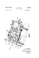
- FIG. 4 is a perspective view of the front end (coil discharge end) of the wire coiling machine, taken in the direction indicated by the arrow IV in FIG. 1;
- FIG. 5 is a rear sectional view of the drive spindle and friction roll take-off taken on plane V-V in FIG. 6, with the friction rolls shown in phantom;
- FIG. 6 is a fragmentary plan view of the top of the spindle and friction roll take-off drive apparatus at the rear of the machine in FIG. 2;
- FIG. 7 is a fragmentary partially exploded view of the rear end of the spindle in FIG. 6, showing a sleeve being removed;
- FIG. 8 is an enlarged sectional view of one of the slide plates and its support means, taken on plane VIII- VIII in FIG. 2;
- FIG. 9 is an elevational perspective view of the second one of the two like slide plates in the apparatus, the first one of which is shown as part of the assembly in FIG. 8;
- FIG. 10 is a reduced side elevational view of one of the two mirror image sector elements in the assembly, and viewed generally on the plane X-X in FIG. 4, but without the attached components being shown;
- FIG. 11 is a perspective view of one of the two mirror image hanger elements in the apparatus.
- FIG. 12 is a fragmentary side elevational view of a front portion of one slide plate, one sector element mounted thereon, its attached hanger, and one work roll suspended on the hanger, viewed in the direction indicated by the arrow XII in FIG.
- FIG. 13 is a fragmentary plan view of the arbor and two work rolls, showing one axially shifted position of the work rolls;
- FIG. 14 is a sectional view of the angle tilt control means for the sectors, hangers and work rolls, taken on the plane XIVXIV in FIG. 15;
- FIG. 15 is a fragmentary enlarged plan view of the frontal portion of the apparatus showing one tilted relationship between the work rolls with respect to each other and the arbor.
- the complete coiling assembly 10 is mounted on a support stand 12 which includes a housing containing a suitable electrical motor 11 and V-belt drive 13 (FIG. 1) to drive the spindle pulleys 16 and 18 (FIG. 2).
- This stand includes an upper platform 14 supporting the main operating components of the coiling machine.
- the central high speed drive spindle 20, driven by attached pulleys 16 and 18, extends substantially the length of the device from front to rear, mounting the mandrel chuck 36 (FIGS. 2, 3 and 15) on the front coil output end, and mounting a friction drive sleeve 22 on the opposite rear end (FIG. 2).
- This spindle is rotatably supported in bearings that are mounted in the upright front and rear walls 24 and 26 of a rigid, vertical boxshaped support which also includes the side walls 28 and 30.
- These four flat walls of steel plates extend vertically and are secured together at their edges to form a rigid central support secured to the platform 14 of the base. All of the driven operative components of the assembly are driven directly or indirectly from this spindle.
- the three main components that must be driven are (1) the high speed Jacobs chuck 36 (FIG. 15) mounted directly on the front end of the spindle and containing 4 the arbor 64 (FIG. 15) on which the wire is coiled, and (2) the arbor-straddling work rolls and 62.
- the work rolls are driven indirectly from the friction drive sleeve 22 (FIG. 2) on the opposite rear end of the spindle 20. That is, sleeve 22, rotated by spindle 20, drives friction rolls 40 and 42 by a frictional engagement therewith. Its diameter is only a small fraction of that of the friction rolls to obtain an immediate speed reduction.
- These friction rolls in turn drive the two flexible drive shafts :44 and 46 respectively (FIG. 6) which extend forwardly astraddle the box-shaped support.
- toothed timing belt pulley gears 48 and 50 are toothed timing belt pulley gears 48 and 50 (FIG.
- the rear end of spindle 20 includes an attached tightenable split coupling 70, and a small diameter rearwardly projecting spindle pin 72.
- a selected metal drive sleeve 22 slides over pin 72 and is rotationally fixed to spindle 20 by the insertion of its reduced diameter neck 22' into the split collar coupling and tightening of Allen screws 71 and 73.
- Sleeve 22 may be substituted by other sleeves of different diameter to obtain a selected drive reduction relationship. In fact, the friction roll may engage the spindle pin itself rather than a sleeve.
- These friction rolls 40 and 42 include outer tires and 82 (FIG. 2) of rubber or the like, mounted on rims 88 and 90, which are integrally connected to axle hubs 84 and 86. These hubs are rotationally mounted on fixed hollow sleeves 94 and 96 secured on their forward ends to a pair of upstanding links 98 and 100 (FIGS. 5 and 6-). Consequently, with rotation of spindle 20, coupling 70 and friction drive sleeve 22, the two friction rolls 40 and 42 are rotated with bearing movement of their hubs 8 4 and 86 around axle sleeves 94 and 96. These friction rollers are not afiixed directly to the flexible drive shafts 44 and 46. Rather, flexible drive shafts 44 and 46.
- Collars 110 and 112 are axially slidable on these rigid pins to allow axial movement of the drive cables 44 and 46 'with respect to the rollers, but are not rotative with respect thereto so that, when sleeve 22 rotates rollers 40 and 42, these pins 118 and 120 rotate collars 110 and 112 which in turn rotate flexible drive shafts 44 and 46.
- This axial adjustment is important to allow slide plate adjustment fore and aft as will be'explained hereinafter.
- rolls 40 and 42 are mounted rotatably to the upper ends of like vertical links 98 and 100.
- These upstanding links are pivotally mounted on their lower ends to a horizontal transverse fixed support 120 affixed to the base of the box type support, and specifically to wall 24.
- the intermediate portions of these links 98 and 100 are interconnected by an adjustment means which includes oppositely threaded shaft portions 122 and 124 interconnected by a center collar 126.
- These two thread sections 122 and 124 have their opposite righthand and left-hand threads extending through and engaging a pair of pivot pins 130 and 132 extending through links 98 and 100 parallel to the link pivot axes.
- control knob 134 on one end of the threaded adjustment means causes both rolls to be simultaneously transversely moved toward or away from drive spindle 22 in a swinging arcuate motion. Since drive shafts 44 and 46 are flexible, this adjustment does not affect the components at the front end of the machine.
- the drive shafts 44 and 46 drive toothed timing belt gear pulleys 48 and 50. More specifically, the front ends of drive shafts 44 and 46 are afiixed in the reduced rear ends and 47 of collars 53 and 55 (FIGS. 13 and 15). These collars have forwardly extending shafts 49 and 51 that extend through and are rotationally supported in the special hangers 150 and 152. Mounted on the ends of shafts 49 and 51 in front of the hangers are gear pulleys 48 and 50. These gear pulleys drive cylindrical work rolls and 62 through timing belts 52, 54, and the gear pulleys 56 and 58, the bottom being mounted to the axles 170 and 171 of the work rolls. These axles 170 and 171 are also mounted rotationally on hangers and 152. The work rolls are mounted in a unique manner allowing adjustment movements in a closely and accurately controlled fashion, with high sensitivity.
- Work rolls 60 and 62 are rotationally mounted respectively on hangers 150 and 152, which in turn are pivotally mounted on sectors 154 and 156, which in turn are arcuately adjustably mounted to forwardly and rearwardly movable slide plates 158 and (FIGS. 8 and 9).
- the two hangers 150 and 152 are mirror image elements of each other, as are the two sectors 154 and 156, while the two slide plates 158 and 160 are essentially identical. For purposes of description, therefore, only one of the hangers and one of the sectors will be described in detail.
- Hanger 150 is illustrated in perspective form in FIG. 11. It is suspended on an axial shaft 166 which extends forwardly and rearwardly, being parallel to the axis of the work roll 60 which it suspends.
- the work roll is attached to the lower end of hanger 150 (FIG. 12) on a rearwardly extending rotational shaft 170.
- the sector is arcuately movable in its plane, parallel to the axis of pin 166 and shaft 170. This movement is indicated by the arcuate arrows in FIG. 12. This arcuate movement is allowed by the bolt and slot connections between each of the sectors and its respective slide plate.
- sector 154 is attached to slide plate 158 by a pair of bolt connections and 182 extending through the sector and through respective arcuate slots 184 and 186 in slide plate 158.
- These arcuate slots have equal radii which have a generation center on a line 190 extending transversely of the device (FIGS. 12 and 15).
- This line serving as a focal point for the radii of the slots for both sectors is a transverse imaginary axis which extends directly through the centers of both work rolls 60 and 62, and through the center of the arbor or mandrel. It also contains the focal center of the radii of arcuate slots and 187 in slide plate 160 (FIG. 1), through which bolts connections 181 and 183 extend to support sector 156. It thus extends through these centers even though the work rolls are arcuately shifted by their mounting sectors 154 and 156. This is important in order to retain coil forming accuracy while allowing operational versatility.
- the arcuate movement of the two sectors occurs simultaneously, one moving clockwise and the other counterclockwise, or vice versa, in a controlled fashion, with movement of the shifting mechanism connected therewith and including adjustment handle 200.
- the vertically extending actuation lever 200 (FIGS. 2 and 14). Its lower portion has a pair of oppositely laterally extending fingers 202 and 204 with spherical balls 206 and 208 affixed to their front faces.
- the sectors 154 and 156 include rearwardly opening, elongated sockets 212 (FIG. 12) and 213 (FIG. 10) receiving the balls 206 and 208 (FIGS. 10, 12 and 15) with a relatively close tolerance. Opposite vertical movement of fingers 202 and 204 causes opposite vertical movement of the balls, and opposite arcuate shifting of sectors 154 and 156.
- a cover 430 (FIG. 3) placed over the box type support for the spindle may have indicia 431 scribed thereon to indicate the relative position of arm 200 and thus the angular relation of the forming rolls.
- the mounting of work roll 62 is essentially the same as 60 except in a mirror image fashion. That is, its rearwardly extending shaft 171 (FIG. 13) is rotationally mounted to the lower end of hanger 152. Axle pins 170 and 171 extend through openings, e.g. opening 250 (FIGS. 11 and 12) in the hangers.
- Hanger 152 is mounted on sector 156 on a front-to-rear pivot shaft 167 parallel to the opposite shaft 166 on the other hanger. This sector likewise is secured in an arcuate fashion to slide plate 160 (FIG. 9) by studs 181 and 183 that extend through arcuate slots 185 and 187 (FIG. 1) for securement of the sector.
- hangers 150 and 152 Since the hangers also suspend the respective shafts 49 and 51 through suitable openings, e.g. opening 59 in hanger 150 (FIG. 11), from flexible drive shafts 44 and 46, arcuate shifting of the hanger members with respect to their pivot pins 166 and 167 does not affect the tautness of timing belts 52 and 54 because both drive pulleys, i.e. 48 and 56 are one hanger and 50 and 58 on the other hanger are retained at the same spacing.
- the shifting of the rolls toward and away from each other with respect to the mandrel is achieved by pivoting hangers 150 and 152 on their respective upper support pins. Since the work rolls are suspended on the lower portions of these hangers, the work rolls move through an arcuate path in the same transverse plane.
- transverse control means composed of a pair of oppositely threaded shaft portions 260 and 262, innerconnected by a flexible torsion spring 264, and having a control knob 266 and locking means 268 on one end, i.e. on shaft portion 262.
- Threaded shaft portions 260 and 262 extend through and are in threaded engagement with openings 263 and 265 (FIGS. 4 and 11) in the hangers. Since portions 260 and 262 are threaded oppositely, i.e. right-hand and left-hand or vice versa, rotation of knob 266 (after loosening of setting knob 268) causes hangers'150 and 152 and thus work rolls 60 and 62 to be moved toward and away from each other.
- the flexible spring 264 is provided between the oppositely threaded portions to enable one of the drive rolls to be axially shifted with respect to each other (as shown in FIG. 13) without affecting the transverse relationship between the rolls.
- the particular diameter work rolls 60 and 62 may be altered by removal of spacer portions 60 and 62' (FIG. 13), and substituting different work rolls on the hubs. To do so, the rolls are spread apart, the substitution is made, and then they are brought back together to the operative spacing from the mandrel to accommodate the mandrel diameter and the wire diameter.
- Axial movement of the work rollls on their axes parallel to each other is achieved by forwardly and rearwardly shifting one or both of the two slide plates 158 and 160. Since each work roll is mounted to its own hanger, and
- each hanger is mounted to its own sector, and each sector is mounted to its own slide plate, forward or rearward movement of a respective slide plate will move these other components also.
- the mounting of slide plate 158 is illustrated in FIG. 8 with that of slide plate 160 being essentially the same.
- Each slide plate is mounted in guideways on its upper and lower edges. More specifically, referring to FIG. 8, plate 158 has the box side wall 28 along the inside face thereof, a lower vertical mounting plate 300 along the lower edge thereof, a small lower retention plate 302 attached to plate 300 and enclosing a lower outside portion of slide plate 158, and an upper T-shaped retention element 306 extending along the upper edge of and the upper outer face portion of slide plate 158.
- the other slide plate 160 has a similar support plate 300, and upper and lower retention plates 302' and 306' (FIG. 1).
- both of these slide plates 158 and 160 are cutouts 310 in plate 158 and 312 in plate 160 having gear racks 314 and 316, respectively.
- Engaging each gear rack is a spur gear, e.g. spur gear 318 (FIG. 8) for rack 314. It is mounted to a shaft 320 that extends through plate 306 and has a control knob 322 thereon. Rotation of knob 322 therefore drives the slide plate 158 forwardly or rearwardly depending upon the direction of rotation. Likewise, rotation of a corresponding knob 324 (FIG. 2) shifts slide plate 160 forwardly or rearwardly.
- the individual slide plates may be locked in a particular adjusted position by tightening the lock knobs 330 or 334 respectively.
- a maynifying glass assembly 420 is normally mounted on a bracket 422 (FIG. 2) above the mandrel to accurately observe the coiling. Further, the apparatus normally has a coil cutter assembly 450 (FIGS. 1 and 3) adjacent the output end of the mandrel to cut the coil C (FIG. 3) being formed into segments.
- This particular cutter subassembly shown is described in detail and claimed in my copending application entitled Indexing Wire Cutter Apparatus, filed Oct. 21, 1965, now Patent 3,370,495. Other cutters may be used with this application.
- the wire ⁇ V can be fed as illustrated in FIG. 4, ie over guide disc 470, under guide disc 472, through an oil bath in container 474, and thence up around one of the work rolls 62 to be formed into a coil C on mandrel 64, as the mandrel spins and the work rolls 60 and 62 rotate to wind the wire around the mandrel and advance it axially oif the free end of the mandrel.
- This method of winding is described and claimed more fully in my copending application entitled Wire Coiling, filed June 23, 1965, now Patent No. 3,359,768 by the inventor herein.
- the wire may be guided up through the guide openings in conventional guide plates 480 (FIG. 4) and directly to the mandrel between the two work rolls as shown by phantom line W in FIG. 4.
- the rate of the relative rotational speed of the mandrel with respect to the work rolls is selectively determined by choosing a particular diameter drive sleeve 22, particular diameter work rolls 60 and 62, and a particular size mandrel diameter to suit the coil diameter desired and the wire diameter being employed.
- Spindle is driven at a selected high speed of several thousand revolutions per minute by the conventional electrical motor, through the conventional V-belt drive to pulleys 16 and 18 (FIG. 2). This spindle is very securely mounted so that, even at very high speeds, no vibration of any appreciable degree is noticed.
- the relative positions of the friction rolls and 42 8 to engage this sleeve are adjusted, using knob 134 (FIG. 5) to swing links 98 and 100.
- Adjustment of the work rolls with respect to each other in a transverse plane to adjust to a particular size wire and mandrel 64 is achieved by turning adjustment knob 266 to swing the two hangers and work rolls inwardly or outwardly.
- the selected size mandrel 64 is inserted in the Jacobs chuck 36 very simply by simply loosening the Jacobs chuck with a key in conventional fashion.
- a Jacobs chuck can be employed in the wire coiling machine (for the first time) because of the out-and-around straddling drive arrangements using the frictional drive out from the central spindle, the flexible drive shafts straddling the assembly, and the timing belts extending back into the work rolls. This provides plenty of space for the Jacobs chuck.
- the selected forwardly and rearwardly shifted position of the forming rolls is obtained by loosening knobs 330 and/or 334, and adjusting spur gear knobs 322 and 324 to shift the slide plates and thus the entire individual assemblies forwardly or rearwardly.
- Arcuate movement of the work rolls in a pivotal action on an imaginary horizontal transverse axis is achieved by loosening set screw 220 and adjusting lever 200 to vertically shift the spherical balls 206 and 208, sectors 154 and 156, hangers, and work rolls to a desired angle.
- the wire is then fed either up over one of the work rolls or directly up to the mandrel as explained heretofore, so that it is continuously coiled upon the mandrel by the spinning mandrel and the two work rolls. These preferably have a revolving relationship of about thirty to one.
- the wire coil C is axially discharged off the end of the mandrel in conventional fashion, and may be cut into segments by the cutter subassembly 450 (FIGS. 2 and 3).
- the steel box support for the one high speed member, the spindle, and the heavy slide plates and sector connections on the slide plates provide a rigid heavy structure for stability.
- the entire machine is symmetrical for complete balanced operation.
- the suspended work rolls on the top mounted hangers enables high sensitivity of work roll adjustment so that a close sensitivity touch can be maintained right at the arbor, which is the spot where the mechanism must be most delicately controlled for top grade coils.
- a wire coiling machine comprising: a powered, rotationally mounted, high speed central drive spindle; a pair of flexible drive shafts generally parallel to, spaced from, and astraddle of said spindle; an arbor receiving chuck on one end of said spindle, and a pair of forming rolls astraddle the spindle axis and adjacent said chuck to straddle an arbor in said chuck; speed reduction timing belt connection means operably between said drive shafts and said forming rolls; said spindle having friction drive peripheral surface means; a pair of friction wheels positioned to be peripherally rotationally driven by said spindle surface means; said friction wheels having couplings rotationally engaged therewith, mounted to said drive shafts, and axially shiftable with respect to said wheels; and said friction wheels having peripheral lengths several times greater than said that of said spindle surface means to effect a speed reduction.
- a wire coiling machine comprising: a rigid support mount means; a drive spindle rotationally mounted on said rigid mount means; an arbor chuck mounted on one end of said spindle to receive a forming arbor coaxially with said spindle; :a pair of rotationally mounted, straddling, coiling rolls adjacent said chuck to straddle an arbor therein; a pair of roll mounting members having an orientation parallel to each other and to said spindle, and supporting said coiling rolls; said members being axially shiftable in said parallel orientation to shift said rolls along the axis of said chuck; a pair of flexible drive shafts operably associated on one end thereof with said rolls, and extending along opposite sides of said spindle, spaced therefrom; a pair of wheels at the opposite end of said shafts, positioned to be peripherally driven by said spindle, and axially shiftable with respect to said shafts; and couplings rotationally drivingly engaged with said wheels and secured to said shafts, whereby rotation of said spindle directly drives said chuck, and indirectly drives
- Wire coiling apparatus comprising: a rotationally mounted, powered, central drive spindle having an arbor chuck on one end coaxial therewith; a pair of powered coiling rolls astraddle the axis of said chuck and spindle, adjacent said chuck, to straddle and cooperate with an arbor in said chuck; a pair of suspension hangers rotationally mounting said rolls; the rotational axes of said rolls being in planes parallel to each other; said hangers being pivotally mounted on axes in planes parallel to each other to be pivoted thereon to allow said rolls to be shiftable toward and away from each other and said chuck axis in arcuate paths; and shift control means operably connected to said hangers to controllably shift them in said arcuate paths.
- Wire coiling apparatus comprising: rigid support means, a powered, central drive spindle rotationally mounted to said support means and having an arbor chuck on one end coaxial therewith; a pair of powered coiling r-olls astraddle the axis of said chuck and spindle, adjacent said chuck, to be cooperative with an arbor in said chuck; a pair of hangers rotationally mounting said rolls; a pair of slide plates on opposite sides of said spindle and shiftable in a direction parallel to the spindle; said hangers being supported by said slide plates and being pivotally mounted on an axis spaced from and parallel to the axis of the respective roll; said hangers being pivotally shiftable toward and away from said chuck axis to shift said rolls with respect to an arbor in said chuck; variable control means operably connected between said hangers to controllably pivot them toward and away from each other and said chuck axis, to thereby control the work relation of said rolls with respect to an arbor in said chuck.
- Wire coiling apparatus comprising: rigid support means; a powered, central drive spindle rotationally mounted to said support means and having an arbor chuck on one end coaxial therewith; a pair of coiling rolls astraddle the axis of said chuck and spindle, adjacent said chuck to be cooperative with an arbor in said chuck; drive connection means from said spindle to said rolls; a pair of hangers rotationally mounting said rolls, a pair of sector members mounted to said support means on opposite sides of said spindle; said hangers pivotally mounted to said sector members on axes spaced from, above, and parallel to the axes of the respective rolls; said hangers being shiftable pivotally toward and away from said chuck axis to shift said rolls arcuately with respect to an arbor in said chuck; variable control means operably connected between said hangers to pivot them toward and away from each other and said chuck axis to control the work relation of said rolls with respect to an arbor in said chuck; said sector members being arcuately shiftable in planes parallel to each other to
- Wire coiling apparatus comprising: rigid support maens; a powered, central drive spindle rotationally mounted to said support means and having an arbor chuck on one end coaxial therewith; a pair of powered coiling rolls astraddle the axis of said chuck and spindle, adjacent said chuck, to be cooperative with an arbor in said chuck; a pair of hangers rotationally mounting said rolls, means pivotally suspending said hangers on said support means on pivot axes spaced from and parallel to the axes of the respective rolls; said hangers being shiftable toward and away from said chuck axis to shift said rolls with respect to an arbor in said chuck; variable control means operably connected between said hangers to pivot them toward and away from each other and said chuck axis to control the work relation of said rolls with respect to an arbor in said chuck; a pair of flexible drive shafts generally parallel to, spaced from, and astraddle of said spindle; a pair of friction wheels rotationally connected with said drive shafts and peripherally engageable with said spindle to be
- a wire coiling machine comprising: a rigid, boxshaped support; a spindle extending through said support, rotationally mounted to two walls thereof, and having opposite ends extending from said walls; an arbor chuck on one of said ends; a pair of flexible rotational drive shafts astraddle said support and extending therebeyond on both ends, and generally parallel to said spindle to extend along the second two walls of said support; a pair of friction rolls rotationally associated with said shafts adjacent the spindle end opposite said chuck, and engageable with said opposite spindle end to be rotationally driven thereby; a pair of slide support means adjacent said second two walls; a pair of roll hangers attached to said slide support means adjacent said chuck; a pair of work rolls rotationally mounted to said hangers to straddle an arbor in said chuck; and timing belt and sprocket means on said hangers, from the respective drive shafts to the respective work rolls, to eifect a smooth, quiet drive connection.
- a wire coiling machine comprising: a rigid, boxshaped support; a spindle extending through said support, rotationally mounted to two walls thereof, and having opposite ends extending from said Walls; an arbor chuck on one of said spindle ends; a pair of flexible rotational drive shafts astraddle said support and extending therebeyond on both ends, and generally parallel to said spindle to extend along the second two walls of said support; a pair of friction wheels attached to the ends of said shafts adjacent the second of said spindle ends, opposite said chuck, and engageable with said second spindle end to be rotationally driven thereby; a pair of slide plate supports and means mounting said a pair of slide plate supports and means mounting said supports adjacent said second two walls; rack and pinion means between said supports and mounting means to shift said supports along said second two walls in planes parallel to each other; a pair of roll hangers attached to said plate supports adjacent said chuck; a pair of work rolls rotationally mounted to said hangers to straddle an arbor in said chuck; and timing belt
- a wire coiling machine comprising: a rotational spindle having an arbor receiving chuck on one end; a pair of slide elements astraddle of, spaced from, and parallel to said spindle; a pair of pivotable hangers, and means pivotally suspending said hangers from said elements on pivot axes in planes parallel to each other; a pair of coiling rolls rotatably mounted to said hangers adjacent said chuck to be astraddle of an anbor therein; said slide elements being shiftable axially of said spindle to vary the axial relationship of said rolls with respect to an arbor in said chuck; and pivot control means connected to said hangers to pivot said hangers and rolls transversely toward and away from each other and an arbor in said chuck.
- a wire coiling machine comprising: a rigid support; a central drive spindle rotationally mounted to and extending from said support, and having an arbor chuck on one extending end to be coaxial therewith; symmetrical roll support and control structure astraddle said spindle, including (1) a pair of slide elements astraddle of, spaced from, and parallel to said spindle, and supported by said support, control means between said support and elements to cause movement of said elements axially of said spindle, (2) a pair of arcuately movable sectors attached respectively to said slide elements and movable within planes parallel to each other, (3) a pair of roll hangers pivotally mounted respectively to said sectors on pivot axes parallel to said spindle, and (4) a pair of coiling rolls rotationally mounted respectively to said hangers on rotational axes generally parallel to said spindle and offset from said pivot axes; said sectors movable in arcs having centers on an imaginary transverse axis through the rotational axes of said rolls and the extended axis of said spin
- a wire coiling machine comprising: support means; a drive spindle rotationally mounted to and extending from said support means, and having an arbor-receiving chuck on one extending end thereof, coaxial therewith; a pair of coiling rolls astraddle the axis of said chuck and spindle, adjacent said chuck to be cooperative with an arbor in said chuck; a pair of sector elements suspended by said support means and having a connection thereto allowing movement of each sector in an are parallel to said spindle; said arcs both having a center on an imaginary transverse axis extending through the axes of said rolls and through the extended axis of said chuck to be through the axis of an arbor therein; and means suspending said rolls from said sector elements.
- a wire coiling machine comprising: a rigid, boxshaped support; a spindle extending through said support, rotationally mounted to two walls thereof, and having opposite ends extending from said walls; an arbor chuck on one of said ends; a pair of flexible rotational drive shafts astraddle said support and extending therebeyond on both ends, and generally parallel to said spindle to extend along the second two walls of said support; said spindle having friction drive peripheral surface means; a pair of friction wheels positioned to be peripherally rotationally driven by said spindle surface means; said friction wheels having couplings rotationally engaged therewith, mounted to said drive shafts, and axially shiftable with respect to said wheels; and said friction wheels having peripheral lengths several times greater than said that of said spindle surface means to effect a speed reduction; said wheels being axially shiftable with respect to said shafts; a pair of slide elements astraddle of, spaced from, and parallel to said spindle, and supported by said support, control means between said support and elements to cause movement of said elements axial
Landscapes
- Engineering & Computer Science (AREA)
- Mechanical Engineering (AREA)
- Winding Filamentary Materials (AREA)
- Wire Processing (AREA)
- Unwinding Webs (AREA)
Priority Applications (4)
| Application Number | Priority Date | Filing Date | Title |
|---|---|---|---|
| US484222A US3401557A (en) | 1965-09-01 | 1965-09-01 | Wire coiling machine |
| SE11022/66A SE319355B (cg-RX-API-DMAC10.html) | 1965-09-01 | 1966-08-15 | |
| DE19661499092 DE1499092B2 (de) | 1965-09-01 | 1966-08-30 | Drahtwickelmaschine |
| GB38863/66A GB1105403A (en) | 1965-09-01 | 1966-08-31 | Wire coiling machines |
Applications Claiming Priority (1)
| Application Number | Priority Date | Filing Date | Title |
|---|---|---|---|
| US484222A US3401557A (en) | 1965-09-01 | 1965-09-01 | Wire coiling machine |
Publications (1)
| Publication Number | Publication Date |
|---|---|
| US3401557A true US3401557A (en) | 1968-09-17 |
Family
ID=23923258
Family Applications (1)
| Application Number | Title | Priority Date | Filing Date |
|---|---|---|---|
| US484222A Expired - Lifetime US3401557A (en) | 1965-09-01 | 1965-09-01 | Wire coiling machine |
Country Status (4)
| Country | Link |
|---|---|
| US (1) | US3401557A (cg-RX-API-DMAC10.html) |
| DE (1) | DE1499092B2 (cg-RX-API-DMAC10.html) |
| GB (1) | GB1105403A (cg-RX-API-DMAC10.html) |
| SE (1) | SE319355B (cg-RX-API-DMAC10.html) |
Cited By (6)
| Publication number | Priority date | Publication date | Assignee | Title |
|---|---|---|---|---|
| US3748435A (en) * | 1971-12-16 | 1973-07-24 | Welding Research Inc | Wire attitude control |
| US4208896A (en) * | 1979-01-29 | 1980-06-24 | S. A. Platt, Inc. | Wire coiling apparatus |
| US4258561A (en) * | 1979-05-21 | 1981-03-31 | S. A. Platt, Inc. | Coiling machine |
| US4561278A (en) * | 1984-09-20 | 1985-12-31 | S. A. Platt, Inc. | Coiling machine |
| US4569216A (en) * | 1985-02-07 | 1986-02-11 | S. A. Platt, Inc. | Sequential variable pitch coiler |
| US4993250A (en) * | 1989-11-17 | 1991-02-19 | S. A. Platt, Inc. | Variable gear ratio coiling machine |
Families Citing this family (1)
| Publication number | Priority date | Publication date | Assignee | Title |
|---|---|---|---|---|
| CN109607300B (zh) * | 2018-11-23 | 2020-08-04 | 湖北三江航天万山特种车辆有限公司 | 一种双电机可调式牵引输送装置 |
Citations (5)
| Publication number | Priority date | Publication date | Assignee | Title |
|---|---|---|---|---|
| US153387A (en) * | 1874-07-21 | Improvement in machines for coiling wire | ||
| US998214A (en) * | 1910-07-25 | 1911-07-18 | John W Wallis | Spiral-tube-making machine. |
| US2227602A (en) * | 1939-08-16 | 1941-01-07 | Stephen A Platt | Automatic coil winding machine |
| US2388401A (en) * | 1943-02-17 | 1945-11-06 | Spiral Binding | Manufacture of helical binders |
| US3082810A (en) * | 1959-12-09 | 1963-03-26 | Stephen A Platt | Wire coiling machine |
-
1965
- 1965-09-01 US US484222A patent/US3401557A/en not_active Expired - Lifetime
-
1966
- 1966-08-15 SE SE11022/66A patent/SE319355B/xx unknown
- 1966-08-30 DE DE19661499092 patent/DE1499092B2/de not_active Withdrawn
- 1966-08-31 GB GB38863/66A patent/GB1105403A/en not_active Expired
Patent Citations (5)
| Publication number | Priority date | Publication date | Assignee | Title |
|---|---|---|---|---|
| US153387A (en) * | 1874-07-21 | Improvement in machines for coiling wire | ||
| US998214A (en) * | 1910-07-25 | 1911-07-18 | John W Wallis | Spiral-tube-making machine. |
| US2227602A (en) * | 1939-08-16 | 1941-01-07 | Stephen A Platt | Automatic coil winding machine |
| US2388401A (en) * | 1943-02-17 | 1945-11-06 | Spiral Binding | Manufacture of helical binders |
| US3082810A (en) * | 1959-12-09 | 1963-03-26 | Stephen A Platt | Wire coiling machine |
Cited By (6)
| Publication number | Priority date | Publication date | Assignee | Title |
|---|---|---|---|---|
| US3748435A (en) * | 1971-12-16 | 1973-07-24 | Welding Research Inc | Wire attitude control |
| US4208896A (en) * | 1979-01-29 | 1980-06-24 | S. A. Platt, Inc. | Wire coiling apparatus |
| US4258561A (en) * | 1979-05-21 | 1981-03-31 | S. A. Platt, Inc. | Coiling machine |
| US4561278A (en) * | 1984-09-20 | 1985-12-31 | S. A. Platt, Inc. | Coiling machine |
| US4569216A (en) * | 1985-02-07 | 1986-02-11 | S. A. Platt, Inc. | Sequential variable pitch coiler |
| US4993250A (en) * | 1989-11-17 | 1991-02-19 | S. A. Platt, Inc. | Variable gear ratio coiling machine |
Also Published As
| Publication number | Publication date |
|---|---|
| SE319355B (cg-RX-API-DMAC10.html) | 1970-01-12 |
| DE1499092A1 (de) | 1970-01-22 |
| DE1499092B2 (de) | 1971-03-18 |
| GB1105403A (en) | 1968-03-06 |
Similar Documents
| Publication | Publication Date | Title |
|---|---|---|
| US3401557A (en) | Wire coiling machine | |
| GB858710A (en) | Improvements in or relating to lathes and other machine tools | |
| JPH0142769B2 (cg-RX-API-DMAC10.html) | ||
| US3589203A (en) | Drive mechanism for balancing machine | |
| US3058365A (en) | Speed change device | |
| US4318665A (en) | Machining center with tool shuttle | |
| US4469285A (en) | Coil winding machine with multi-axis positioning for winding television deflection coils | |
| DE3562726D1 (en) | Apparatus for longitudinally stretching a plastics film | |
| SE454251B (sv) | Robothandled med anordning for justering av kuggspel | |
| US2571632A (en) | Machine for continuous polishing of wire or rods | |
| US3570290A (en) | Straightening machine for round workpieces | |
| US4280368A (en) | Devices for producing vibratory forces | |
| US2305564A (en) | Saw filing device | |
| US4993250A (en) | Variable gear ratio coiling machine | |
| US3306597A (en) | Flame cutting machine | |
| US4221136A (en) | Sewing machine and speed adjustment mechanism thereof | |
| US2069052A (en) | Casing machine | |
| US396283A (en) | Edward d | |
| US3570368A (en) | Duplicating apparatus | |
| US4112819A (en) | Apparatus for producing cams | |
| US2499657A (en) | Drill head | |
| US3037331A (en) | Lens grinding device | |
| US3089356A (en) | Belt drive for paper punch | |
| US1228110A (en) | Boring-machine. | |
| US2554830A (en) | Abrading apparatus |