US3338494A - Web accumulator - Google Patents
Web accumulator Download PDFInfo
- Publication number
- US3338494A US3338494A US482808A US48280865A US3338494A US 3338494 A US3338494 A US 3338494A US 482808 A US482808 A US 482808A US 48280865 A US48280865 A US 48280865A US 3338494 A US3338494 A US 3338494A
- Authority
- US
- United States
- Prior art keywords
- conveyor
- pile
- housing
- web
- cloth
- Prior art date
- Legal status (The legal status is an assumption and is not a legal conclusion. Google has not performed a legal analysis and makes no representation as to the accuracy of the status listed.)
- Expired - Lifetime
Links
- 239000004744 fabric Substances 0.000 description 42
- 239000000463 material Substances 0.000 description 4
- 230000007246 mechanism Effects 0.000 description 4
- 239000004809 Teflon Substances 0.000 description 3
- 229920006362 Teflon® Polymers 0.000 description 3
- 238000004519 manufacturing process Methods 0.000 description 3
- 239000004753 textile Substances 0.000 description 3
- 239000000523 sample Substances 0.000 description 2
- 229910001220 stainless steel Inorganic materials 0.000 description 2
- 239000010935 stainless steel Substances 0.000 description 2
- 239000000126 substance Substances 0.000 description 2
- 239000003831 antifriction material Substances 0.000 description 1
- 238000006243 chemical reaction Methods 0.000 description 1
- 238000010276 construction Methods 0.000 description 1
- 239000000835 fiber Substances 0.000 description 1
- 238000009434 installation Methods 0.000 description 1
- 238000009413 insulation Methods 0.000 description 1
- 230000014759 maintenance of location Effects 0.000 description 1
- 238000000034 method Methods 0.000 description 1
- 238000012986 modification Methods 0.000 description 1
- 230000004048 modification Effects 0.000 description 1
- 239000004033 plastic Substances 0.000 description 1
- 230000008569 process Effects 0.000 description 1
- 230000000717 retained effect Effects 0.000 description 1
- 230000001360 synchronised effect Effects 0.000 description 1
- 238000009988 textile finishing Methods 0.000 description 1
- 239000002023 wood Substances 0.000 description 1
Images
Classifications
-
- D—TEXTILES; PAPER
- D06—TREATMENT OF TEXTILES OR THE LIKE; LAUNDERING; FLEXIBLE MATERIALS NOT OTHERWISE PROVIDED FOR
- D06B—TREATING TEXTILE MATERIALS USING LIQUIDS, GASES OR VAPOURS
- D06B17/00—Storing of textile materials in association with the treatment of the materials by liquids, gases or vapours
- D06B17/02—Storing of textile materials in association with the treatment of the materials by liquids, gases or vapours in superimposed, i.e. stack-packed, form; J-boxes
-
- B—PERFORMING OPERATIONS; TRANSPORTING
- B65—CONVEYING; PACKING; STORING; HANDLING THIN OR FILAMENTARY MATERIAL
- B65H—HANDLING THIN OR FILAMENTARY MATERIAL, e.g. SHEETS, WEBS, CABLES
- B65H20/00—Advancing webs
- B65H20/28—Mechanisms for delivering webs in superposed folds and refeeding them from the lower end of the folded assemblies
-
- D—TEXTILES; PAPER
- D06—TREATMENT OF TEXTILES OR THE LIKE; LAUNDERING; FLEXIBLE MATERIALS NOT OTHERWISE PROVIDED FOR
- D06C—FINISHING, DRESSING, TENTERING OR STRETCHING TEXTILE FABRICS
- D06C3/00—Stretching, tentering or spreading textile fabrics; Producing elasticity in textile fabrics
-
- D—TEXTILES; PAPER
- D06—TREATMENT OF TEXTILES OR THE LIKE; LAUNDERING; FLEXIBLE MATERIALS NOT OTHERWISE PROVIDED FOR
- D06C—FINISHING, DRESSING, TENTERING OR STRETCHING TEXTILE FABRICS
- D06C2700/00—Finishing or decoration of textile materials, except for bleaching, dyeing, printing, mercerising, washing or fulling
- D06C2700/10—Guides or expanders for finishing
Definitions
- This invention relates generally to web handling equipment and more particularly is directed towards improvements in accumulators of the sort employed for the continuous processing of cloth.
- fabric may be bleached on a continuous 'basis by chemically treating it and maintaining a section of it within an enclosure for a specified period during which it may be exposed to a steam atmosphere. The cloth is retained within the enclosure long enough for the chemicals to react.
- I-Box is a J-shaped housing providing an enclosure for fabric which is fed in and sometimes folded to form a vertical stack or pile, either as roped cloth or in the open width form in the higher leg of the housing.
- the stack moves under its own weight down through the housing and is drawn off through the shorter leg of the J-Box.
- Another object of this invention is to provide means for increasing the capacity of a J-Box style accumulator without harmful results to the fabric being processed.
- a further object of this invention is to provide an accumulator which is readily adjustable to fabrics of various Widths.
- a still further object of this invention is to provide improved means for uniformly and simultaneously tensioning a pair of cooperating conveyor chains.
- Yet another object of this invention is to provide im proved. means for feeding cloth into a vertical chute or stack.
- this invention features an accumulator for use in treating running lengths of open width textile materials, comprising a housing defining a vertical chamber in which incoming cloth is fed or dropped into a vertical pile.
- the housing also includes a horizontal portion in which is mounted a conveyor system adapted to carry the lower portion of the pile at a predetermined speed towards the discharge end of the housing.
- the discharge end of the conveyor is vertically oriented so that the fabric is removed from the pile in substantially the same manner in which it was delivered.
- the linear speed of the conveyor is adjusted to coincide with the linear speed of the accumulated cloth fed into the housing and in this fashion the weight of the stack will not exceed prescribed limits and yet the total capacity of the unit is greatly increased by reason of the conveyor supporting the load.
- Another feature of this invention resides in an adjustable chute which is readily set to the width of the cloth being processed in order to support properly the stacked material.
- the chute comprises a pair of opposing guides supported for movement to or away from one another by means of drivingly connected double-threaded lead screws.
- the invention also features a system for tensioning simultaneously a pair of separate cooperating chains, comprising a pair of sprockets each engaging an associated chain.
- Each pulley is connected by an arm to a common shaft, the axis of which is parallel to the pulley axes and which is angularly adjustable about its axis for applying tension to the belts.
- One of the arms supporting one of the pulleys is angularly adjustable within certain limits to compensate for differences in lengths of the two chains.
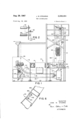
- FIG.1 is a view in side elevation, partly broken away, of an accumulator made according to the invention.
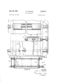
- FIG. 2 is a fragmentary front elevation of the web feed assembly
- FIG. 3 is a fragmentary front'elevation, partly broken away showing details of the adjustable guide chute assembly
- FIG. 4 is a cross-sectional view taken along the line 44 of FIG. 3,
- FIG. 5 is a fragmentary side elevation corresponding to FIG. 3,
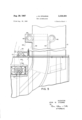
- FIG. 6 is a detail side view showing details of the temperature sensing bulb mounting assembly
- FIG. 7 is a fragmentary detail side view on an enlar-ged scale showing the guide feed assembly
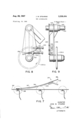
- FIG. 8 is a detail side view of a conveyor chain adjusting assembly
- FIG. 9 is a-front elevation thereof.
- an accumulator in the form of a modified J-Box and comprising a housing 10 typically 6 feet or so in Width and about 19 or so feet high.
- the housing 10 includes a lower mid-section 14 about 5 /2 feet high and a discharge section 16 about 7 /2 feet high.
- the apparatus is adapted to accumulate a moving web 20 of cloth or the like which is fed into the housing near the bottom of the stack 12, is carried up to the top thereof and dropped down or folded to form a vertical pile 22 in the stack 12.
- the pile of folded cloth is guided from the stack onto the moving conveyor 18 by means of a curved guide 24.
- the conveyor 18 carries the pile horizontally along through the housing at a speed adjusted to coincide with the exact linear speed of the accumulated cloth pile being deposited on it.
- the pile is carried along towards the discharge section 16 where it is inclined upwardly to a nearly vertical position.
- the web is then drawn off from the pile through a discharge opening 26 with the pile being in a position similar to that in which the cloth was first piled. This allows the cloth to be pulled off the top of the pile rather than from underneath it.
- a conventional J-Box employing a stationary sur face for the cloth pile, the friction of the pile moving over the fixed surface causes the lower portion of the pile to advance more slowly than upper portion.
- the apparatus will now be described in detail.
- the web 20 is fed into the accumulator through the right hand wall of the housing as viewed in FIG. 1 around a roller 30 rotatably mounted near the lower part of the stack 12.
- the web 20 is then carried to the upper portion of the stack where it is roven over, under and over a set of feed rolls, 32, 34 and 36.
- These feed rolls deliver the web downwardly into a vertical chute defined by front and rear walls 38 and 40 mounted upright within the stack 12.
- the web, as it folds back and forth in the chute forms the vertical pile 22.
- the height of the pile is normally maintained below the top of the chute in order to keep the weight of the pile below a predetermined limit.
- the lower roll 34 has been mounted in a counterbalanced arrangement shown best in FIG. 2. Each end of the roll 34 is suspended from a pulley 42 with a weight 44 providing the counterbalance. It will be understood that with this arrangement, the roller 34, which is free to move up and down within a certain range, will provide a continuous drag on the web to insure that the web is held in good frictional contact against the roller 36. In the event that the pile 22 becomes so high that the natural weight of the cloth strand between the feed roller 36 and the top of the pile may be insufficiently heavy to insure a good frictional contact with the roll 36, the roller 34 will drop downwardly to provide the needed drag.
- One other arrangement for insuring a driving contact between the web and the roll 36 is to operate the rollers at different speeds as by V belts and variable diameter pulleys with the roll 36 rotating at a speed greater than the roll 34 and the roll 34 operating faster than the roll 32. This will maintain continuous frictional contact with the web against the roll despite variations in the weight of the olfcoming cloth.
- an adjustable pile guiding mechanism comprising a pair of side panels 42 and 44 which cooperate with the walls 38 and 40 to form the vertical chute.
- the guide panels 42 and 44 are supported by a pair of spaced lead screws 46 and 48 at the upper end of the stack and by a single lead screw 56 at the lower end thereof. All of the lead screws are reversely threaded so that one end of the screw has right hand threads and the other end has left hand threads.
- the panels 42 and 44 engage the lead screws by means of tapped followers 52 and the outer ends of the lead screws are rotatably mounted in bearings 56 supported by the stack 12.
- the upper lead screws 46 and 48 are drivingly connected by means of a chain belt 58 looped over spocket gears 60 and 62 mounted on the left hand ends of the lead screws as shown in FIG. 4. In this fashion the two lead screws operate in unison.
- the right hand end of the lead screw 48 is also provided with a sprocket gear 64 and engages a chain belt 66 drivingly connected to a sprocket gear 68 mounted on the right hand end of the lower lead screw 50.
- the sprocket 68 is provided with a crank handle whereby rotation of the sprocket 68 will operate the lead screws 46, 48 and 50 in unison moving the guide panels 42 and 44 to or away from one another as desired to adjust the operating width of the guides according to the width of the cloth being processed. While in the illustrated embodiment the guide panels 42 and 44 are shown in use only in the vertical stack section of the unit, they may also be extended so as to run alongside the conveyor 18 should it be necessary or desirable. The arrangement permits a quick and easy adjustment of the apparatus.
- a scale mechanism 70 In order to provide a ready indication of the position of the guide panels, a scale mechanism 70, best shown in FIG. 4, is provided.
- This scale mechanism comprises a lead screw 72 rotatably mounted in bearings 74 and 76 and actuated by a sprocket gear 78 in mesh with the chain belt 66.
- the follower 80 is threaded to the lead screw and is provided with a pointer 82 which moves along behind a scale 84 when the sprocket 68 is operated.
- the scale 84 is marked off in inches, typically from 36" to 68" this being the normal range of fabric widths. It will thus be understood that an operator may quickly and easily position the guide panels by operating one single handwheel which in turn, rotates the sprocket 68 until the pointer 82 lines up with the desired width indicated on the scale 84.
- FIG. 6 there is shown details in construction of a probe mounting assembly wherein a probe such as a temperature bulb 86 is mounted on the back surface of a curved wall 88 forming part of the guide 24.
- the bulb is held in place by means of studs 90 engaging a plate 92 which bears against the bulb and holds it in against the wall 88.
- the lower portion of the guide 24 is best shown in FIG. 7 where it will be seen that the wall 88 carries a replaceable curved spring member 94 which serves to guide the pile of cloth smoothly onto a belt 96 which is part of the conveyor 18.
- the curved spring member 94 typically is fabricated from stainless steel and is coated, at least on its upper surface, with a smooth, tough, high temperature plastic material such as sold under the trademark, Teflon by Du Font and indicated generally by the reference character 97.
- Teflon is also provided in an extra thick layer 98 along the under edge of the free end of the spring member 94 whereby a wearing surface is provided.
- the weight of the cloth pile will force the curved spring member 94 downwardly so that the free end will ride against the upper reach of the conveyor belt 96 and the cloth pile will move smoothly onto the belt.
- the Teflon strip 98 serves to ride against the belt, and by reason of its low coefficient of friction provides an excellent wearing surface.
- the spring member is mounted on a backing plate 100 which together with the spring member is screwed onto the lower end of the wall 88 and a bracket 102. In this fashion the curved spring member 94 may be quickly and easily replaced should it become worn without the necessity of a major overhaul.
- the conveyor 18 comprises three pairs of sprocket gears, 104, 106
- the chain belts 110 carry the belt 96 with the cloth pile from the point of deposit at the end of the curved guide 24 horizontally through the mid section 14 to the discharge section 16. Near the end of the travel of the pile, the chain belt follows a curved path which is defined by fixed side guide elements 112 and 114 disposed above and below the chain belts. These guide elements define a curve from the horizontal portion on the conveyor up to the sprocket gear 108 and this curve corresponds generally to the curve defined by the guide 24 at the point of entry onto the conveyor.
- FIG. 1 there is shown a tensioning. mechanism comprising a pneumatic or' hydraulic cylinder 118 mounted on the exterior of the housing and having a rod 120 engaging a link 122.
- the link 122 is keyed to a shaft 124 rotatably mounted in bearings 126.
- the shaft 124 extends the width of the housing and carries a pair of arms 128 which support the sprocket gears 126 in spaced parallel relation. It will be understood that by actuating the cylinder 118, the shaft 126 may be rotated to angularly adjust the depending arms 128 in order to provide a desired pressure or tension on the chain belts through the sprocket gears 106 thereby eliminating slack in the conveyor.
- one of the arms 128 is a simple one-piece member keyed to the shaft 126 and supporting one of the sprockets 106.
- the other of the arms is angularly adjustable about the shaft 126 in order to accommodate differences in lengths of the chain belts.
- the adjustable arm comprises a pair of hubs 130 and 132 mounted over the shaft 126 with the hub 130 being keyed to the shaft while the hub 132 is rotatable thereabout.
- the hub 130 is fixed to an arm member 134 to which is mounted a pair of spaced lugs 136 and 138 with the lug 136 being located below and to the left of the lug 138.
- the lug 138 is tapped and carries a bolt 140 which in turn carries a lock nut 142.
- the hub 132 which is held in position by means of a collar 144, carries an arm member 146 suspended in spaced parallel relation to the arm member 134.
- the arm member 146 is provided with a plate 148 which extends between the lugs 136 and 138 on the arm member 134.
- the plate 148 is tapped at its lower end to receive a bolt 150 which carries a lock nut 152, as shown in FIG. 8, the left hand end of the bolt 150 bears against the lug 136 while the left hand end of the bolt 140 bears against the plate 148.
- the arm member 146 which carries the sprocket gear 106 (A) may be angularly adjusted about the shaft 126 by manipulation of the bolts 140 and 150. Once the angular setting is obtained so that the same tension is applied to both chain belts, the lock nuts 142 and 152 may be tightened up against the lug 138 and the plate 148 respectively.
- the housing may be maintained in an effectively sealed condition insofar as the belts may be adjusted from outside the housing through a rotary seal at the ends of the shaft 126.
- the apparatus illustrated and described herein greatly increases the capacity of J-boxes without damage to the cloth.
- a wellformed pile is obtained to provide optimum processing of the cloth.
- the importance of a well-formed pile of the proper weight is that much more efiicient processing is obtained. Piles which are too heavy or poorly formed damage the cloth while piles that are too light do not handle properly.
- a well-formed pile is obtained and this pile is guided carefully onto the conveyor which carries it smoothly along to the discharge end of the accumulator where it is tilted upwardly and the cloth removed in substantially the same manner as it was delivered without pulling, crushing or creasing the cloth.
- the pile is carried through smooth wide turns, one at the base of the stack where it is guided onto the conveyor and the other at the discharge end where it is tilted to a nearly vertical position. Both changes of direction are extremely smooth and are on the order of or more so that there is no danger of upsetting the pile but rather the pile is maintained throughout its travel in the Well-formed condition in which it is first formed.
- Apparatus for accumulating a section of a running web comprising (a) a housing,
- Apparatus according to claim 1 including a stratum of antifriction material covering at least a pile engaging surface of said member at the conveyor engaging edge thereof.
- Apparatus for accumulating a section of a running web comprising (a) a housing,
- Apparatus for accumulating a section of a running web comprising (a) a housing,
- Apparatus for accumulating a section of a running web comprising (a) a housing,
- walls including sidewalls defining a chute of substantial height at said one end of said housing
- one of said walls including a curved lower portion terminating at one end of said conveyor
- Apparatus according to claim 5 including visible scale means responsive to movement of said sidewalls for indicating the position thereof.
- Apparatus according to claim 5 including conveyor moving means synchronized to move said conveyor at the same linear speed as the accumulated web pile being placed thereon.
Landscapes
- Engineering & Computer Science (AREA)
- Textile Engineering (AREA)
- Chemical & Material Sciences (AREA)
- Materials Engineering (AREA)
- Treatment Of Fiber Materials (AREA)
- Folding Of Thin Sheet-Like Materials, Special Discharging Devices, And Others (AREA)
Priority Applications (3)
| Application Number | Priority Date | Filing Date | Title |
|---|---|---|---|
| US482808A US3338494A (en) | 1965-08-26 | 1965-08-26 | Web accumulator |
| US620177A US3446409A (en) | 1965-08-26 | 1967-03-02 | Adjustable guide wall assembly |
| BE699313D BE699313A (OSRAM) | 1965-08-26 | 1967-05-31 |
Applications Claiming Priority (1)
| Application Number | Priority Date | Filing Date | Title |
|---|---|---|---|
| US482808A US3338494A (en) | 1965-08-26 | 1965-08-26 | Web accumulator |
Publications (1)
| Publication Number | Publication Date |
|---|---|
| US3338494A true US3338494A (en) | 1967-08-29 |
Family
ID=23917529
Family Applications (1)
| Application Number | Title | Priority Date | Filing Date |
|---|---|---|---|
| US482808A Expired - Lifetime US3338494A (en) | 1965-08-26 | 1965-08-26 | Web accumulator |
Country Status (2)
| Country | Link |
|---|---|
| US (1) | US3338494A (OSRAM) |
| BE (1) | BE699313A (OSRAM) |
Citations (3)
| Publication number | Priority date | Publication date | Assignee | Title |
|---|---|---|---|---|
| US284323A (en) * | 1883-09-04 | Delivery apparatus for machines for finishing fabrics | ||
| US2626145A (en) * | 1947-04-05 | 1953-01-20 | Int Cellucotton Products | Tissure interfolding method and apparatus |
| US2825556A (en) * | 1954-09-01 | 1958-03-04 | Du Pont | Open-width fabric piling apparatus |
-
1965
- 1965-08-26 US US482808A patent/US3338494A/en not_active Expired - Lifetime
-
1967
- 1967-05-31 BE BE699313D patent/BE699313A/xx unknown
Patent Citations (3)
| Publication number | Priority date | Publication date | Assignee | Title |
|---|---|---|---|---|
| US284323A (en) * | 1883-09-04 | Delivery apparatus for machines for finishing fabrics | ||
| US2626145A (en) * | 1947-04-05 | 1953-01-20 | Int Cellucotton Products | Tissure interfolding method and apparatus |
| US2825556A (en) * | 1954-09-01 | 1958-03-04 | Du Pont | Open-width fabric piling apparatus |
Also Published As
| Publication number | Publication date |
|---|---|
| BE699313A (OSRAM) | 1967-11-03 |
Similar Documents
| Publication | Publication Date | Title |
|---|---|---|
| NL192298C (nl) | Inrichting voor het toevoeren van een verpakkings-kunststoffilm in een verpakkingsmachine voor producten. | |
| US3954543A (en) | Label applicator | |
| US4093205A (en) | French folder construction | |
| US2624934A (en) | Method of and apparatus for heat treatment of filamentary material | |
| US3546067A (en) | Apparatus for breaking the curl in traveling material webs formed of paper,cardboard or the like | |
| US4441664A (en) | Apparatus for feeding web material from a supply roll | |
| US3616502A (en) | Apparatus for treating of tubular fabrics | |
| US1347714A (en) | Cloth opener, spreader, and guider | |
| US3446409A (en) | Adjustable guide wall assembly | |
| US4676494A (en) | Cloth support and feed apparatus for cloth spreading machine | |
| US4019700A (en) | Beam creel | |
| US4076184A (en) | Apparatus for reeling web- or strand-like material | |
| US2668572A (en) | Method of and apparatus for coating fabric on either or both faces | |
| US2753706A (en) | Compensating rolls for handling continuous lengths of materials in the form of strand, ropes, and the like | |
| US2062008A (en) | Uniform tension device | |
| US4984341A (en) | Apparatus for controlling tension in a traveling yarn | |
| US3338494A (en) | Web accumulator | |
| US2333278A (en) | Yarn apparatus | |
| US4052245A (en) | Centering device | |
| US2946177A (en) | False twisting machines | |
| US4114791A (en) | Feeding mechanism | |
| US2797086A (en) | Control apparatus | |
| GB2029804A (en) | Unwinding and Feeding Webs | |
| US3110432A (en) | Apparatus for moving tow | |
| US4196832A (en) | Apparatus for the dwell treatment of textile webs |