US4676494A - Cloth support and feed apparatus for cloth spreading machine - Google Patents
Cloth support and feed apparatus for cloth spreading machine Download PDFInfo
- Publication number
- US4676494A US4676494A US06/778,900 US77890084A US4676494A US 4676494 A US4676494 A US 4676494A US 77890084 A US77890084 A US 77890084A US 4676494 A US4676494 A US 4676494A
- Authority
- US
- United States
- Prior art keywords
- roller
- feed
- cloth
- roll
- invention according
- Prior art date
- Legal status (The legal status is an assumption and is not a legal conclusion. Google has not performed a legal analysis and makes no representation as to the accuracy of the status listed.)
- Expired - Fee Related
Links
- 239000004744 fabric Substances 0.000 title claims abstract description 149
- 230000033001 locomotion Effects 0.000 claims description 6
- 230000008878 coupling Effects 0.000 claims 1
- 238000010168 coupling process Methods 0.000 claims 1
- 238000005859 coupling reaction Methods 0.000 claims 1
- 230000037303 wrinkles Effects 0.000 description 4
- 230000005540 biological transmission Effects 0.000 description 2
- 239000000463 material Substances 0.000 description 2
- 125000006850 spacer group Chemical group 0.000 description 2
- 238000009825 accumulation Methods 0.000 description 1
- 239000003638 chemical reducing agent Substances 0.000 description 1
- 239000004020 conductor Substances 0.000 description 1
- 238000010276 construction Methods 0.000 description 1
- 238000012544 monitoring process Methods 0.000 description 1
- 230000002093 peripheral effect Effects 0.000 description 1
- 230000002441 reversible effect Effects 0.000 description 1
- 238000005096 rolling process Methods 0.000 description 1
- 238000007665 sagging Methods 0.000 description 1
Images

Classifications
-
- B—PERFORMING OPERATIONS; TRANSPORTING
- B65—CONVEYING; PACKING; STORING; HANDLING THIN OR FILAMENTARY MATERIAL
- B65H—HANDLING THIN OR FILAMENTARY MATERIAL, e.g. SHEETS, WEBS, CABLES
- B65H16/00—Unwinding, paying-out webs
- B65H16/02—Supporting web roll
-
- B—PERFORMING OPERATIONS; TRANSPORTING
- B65—CONVEYING; PACKING; STORING; HANDLING THIN OR FILAMENTARY MATERIAL
- B65H—HANDLING THIN OR FILAMENTARY MATERIAL, e.g. SHEETS, WEBS, CABLES
- B65H16/00—Unwinding, paying-out webs
- B65H16/10—Arrangements for effecting positive rotation of web roll
- B65H16/106—Arrangements for effecting positive rotation of web roll in which power is applied to web roll
-
- D—TEXTILES; PAPER
- D06—TREATMENT OF TEXTILES OR THE LIKE; LAUNDERING; FLEXIBLE MATERIALS NOT OTHERWISE PROVIDED FOR
- D06C—FINISHING, DRESSING, TENTERING OR STRETCHING TEXTILE FABRICS
- D06C3/00—Stretching, tentering or spreading textile fabrics; Producing elasticity in textile fabrics
- D06C3/02—Stretching, tentering or spreading textile fabrics; Producing elasticity in textile fabrics by endless chain or like apparatus
Definitions
- This invention relates to a cloth spreading machine, and more particularly to a cloth feed apparatus for a cloth spreading machine.
- a pair of parallel fluted rollers support a cloth roll and are adapted to be driven to feed a web of cloth from the cloth roll supported by the rollers.
- the circumferentially spaced alternating ribs and depressions in the fluted rollers accumulate slack created by the weight of the roll engaging the rollers, and the web fed from the roll is less wrinkled when spread upon the cutting table.
- the cloth feed apparatus made in accordance with this invention includes a pair of freely rotatable parallel support rollers for supporting substantially the entire weight of the cloth roll and a separate rotatable cloth feed element engaging the feed roll sufficiently for rotating the cloth roll on the support rollers and feeding the cloth from the roll, but without bearing any substantial portion of the weight of the cloth roll.
- the rotatable cloth feed element preferably takes the form of a driven cloth feed roll having a plurality of transversely spaced annular gripping members including circumferentially spaced cleats or ribs for firmly gripping the outer surface of the cloth roll and feeding a web of cloth from the roll.
- the cloth feed element also includes a plurality of front and rear feed belts all of which are entrained about the cloth feed roller, spaced transversely apart and projecting forward and rearwardly of the cloth feed roller and in tangential engagement with the cloth roll.
- the front feed belts pass around the front support roller and the rear belts pass around the rear support roller so that the support rollers which bear the weight of the cloth roll also support the feed belts and hold the belts in continuous engagement with the outer surface of the cloth roll.
- the cloth feed apparatus made in accordance with this invention also contemplates a movable rear retainer roller for assisting in holding the cloth roll in its operative position on the support rollers while the retainer roller is in an upright retaining position.
- the rear retainer roller is preferably linked with a dancer roller in front of the cloth roll for monitoring the slack in the web fed from the cloth roll and for controlling the speed of the cloth feed roller. The linkage between the dancer roller and the rear retainer roller permits the dancer roller to be locked in an elevated threading position while the rear retainer roller is in a lowered loaded position.
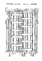
- FIG. 1 is a top plan view of the cloth feed apparatus made in accordance with this invention.
- FIG. 2 is an enlarged side sectional elevation of the cloth feed apparatus, with a cloth roll shown in operative position, and taken along the line 2--2 of FIG. 1;
- FIG. 3 is an enlarged section taken along the line 3--3 of FIG. 2, disclosing the construction of an annular gripping member
- FIG. 4 is a side elevational view taken along the line 4--4 of FIG. 2, illustrating the linkage between the dancer roller and the rear retainer roller.
- FIGS. 1 and 2 disclose a cloth roll support frame 10, adapted to be mounted on a cloth spreading machine and having a pair of parallel side walls or plates 11 and 12 secured together and spaced apart by appropriate spacer rods, such as the spacer rod 13.
- a front support roller 15 Freely rotatably journaled in bearings 14 mounted on the side walls 11 and 12 is a front support roller 15. Likewise journaled in bearings 16 in the side walls 11 and 12 for free rotatable motion is a rear support roller 17.
- the support rollers 15 and 17 are both mounted to extend transversely of the frame 10 and parallel to each other.
- the support rollers 15 and 17 are spaced apart a distance substantially less than the diameter of a cloth roll or supply roll 18 and are adapted to support substantially the entire weight of the cloth roll 18.
- Journaled in bearings 21 in the side walls 11 and 12 is an elongated transverse feed shaft 19 supporting a cloth feed roller 20 parallel to and preferably midway between, the support rollers 15 and 17.
- the feed shaft 19 is driven from a cloth feed motor 22 through a transmission 23, which can be in the form of a gear reducer or a chain and sprocket speed reducing mechanism, mounted on the side wall 11 (FIG. 1).
- the cloth feed motor 22 may be reversible in order to wind or unwind the cloth web 24 from the supply roll 18.
- Each annular gripping member 25 includes a plurality (4 in the drawings) elongated cleats 26 circumferentially spaced about the periphery of the cloth feed roll 20. Furthermore, the cleats 26 may be encompassed by an annular band of gripping material 27 having a peripheral surface of a high co-efficient of friction, such as knurled or embossed rubber or plastic band material. On a cloth feed roller 20 having a 3" diameter, each cleat 26 may project approximately 1/4 of an inch from the periphery of the feed roller 20. The circumferential spacing between the cleats 26 on each gripping member 25 is sufficient to accumulate slack portions of the cloth roll 18.
- the front belt roller 30 is in general planar alignment with the cloth feed roller 20 and the front support roller 15. Trained around the cloth feed roller 20 and the front belt roller 30 are a plurality of transversely spaced front endless feed belts 32. The front feed belts 32 also pass around the intermediate front support roller 15.
- rear belt roller 35 Journaled in the bearings 34 on the side walls 11 and 12 to the rear of the rear support roller 17 is a rear belt roller 35. Trained about the cloth feed roller 20 and the rear belt roller 35 and spaced transversely between the front feed belts 32 and the annular gripping members 25, are a plurality of transversely spaced endless rear feed belts 37. The rear feed belts 37 also pass around the rear support roller 17.
- each of the support rollers 15 and 17 is preferably located slightly above the respective belt planes.
- the top surface of the rear support roller 17 extends above the tangential plane 38 of the top surfaces of the cloth feed roller 20 and the rear belt roller 35, so that the support roller 17 carries the top leg of the rear belt 37 slightly above the normal tangential belt plane 38.
- the main reason for this slight elevation of the support rollers 15 and 17 is to permit only the support rollers 15 and 17 to bear substantially all of the weight of the cloth roll 18. As indicated in FIG.
- neither the front belt roller 30 nor the rear belt roller 35 are touching the bottom surface of the cloth roll 18. Even if the cloth roll 18 were not tightly wound, or the cloth roll 18 were larger, and the bottom surface of the cloth roll 18 were actually touching the belt rollers 30 and/or 35, nevertheless, neither the belt rollers 30 or 35 would sustain much, if any of the weight of the cloth roll 18.
- the cloth feed roller 20 is only in sufficient tangential engagement with the bottom surface of the cloth roll 18 to permit the cleats 26, the frictional annular bands 27, and the endless front and rear belts 32 and 37, to engage the outer bottom surface of the cloth roll 18 to rotate the cloth roll 18 without bearing a significant portion of the weight of the cloth roll 18.
- the support rollers 15 and 17 may be adjustable in directions perpendicular to the tangential plane 38 in order to be moved radially toward or away from the cloth roll 18 so that the support rollers 15 and 17 will support the maximum, or substantially the entire, weight of the particular cloth roll 18 mounted in the frame 10.
- the dancer roller 40 is pivotally linked by a connecting arm 44 to a lever arm 45 pivotally mounted about the bearing 46. Pivotally mounted to the lever arm 45 and extending upward, is a rack member 47 engaging a rotary gear 48, in hidden lines, on a rotary potentiometer 50 which is electrically connected through the conductor 51 to the cloth feed motor 22.
- the dancer roller 40 senses the slack in the cloth web 24 and through its linkage to the potentiometer 50 controls the speed of the feed of the cloth roll 18.
- the cloth web 24 is spread at a speed commensurate with the speed of the cloth spreading machine supporting the frame 10 along a cutting table, not shown.
- a rear retainer roller 55 is journaled between a pair of pivot arms 56, the lower ends of which are fixed to a pivot shaft 57 journaled in the opposite side walls 11 and 12.
- the pivot shaft 57 may be driven by an electrical motor 58 through a transmission 59 (FIG. 1).
- the cloth roll 18, supported in its operative position upon the support rollers 15 and 17, is prevented from inadvertently rolling rearwardly out of the frame 10.
- the pivot shaft 57 is driven so that the rear retainer roller 55 is in a lower loading position, as illustrated in phantom in FIG. 2, the cloth roll 18 may be easily loaded or rolled over the rear retainer roller 55 into its operative position upon the support rollers 15 and 17.
- the pivot shaft 57 is provided with a connecting arm 60 to a long link bar 61 pivotally connected by pin 62 to the lever arm 45 connected to the dancer roller 40.
- the connection between the connecting arm 60 and the link bar 61 is provided by a pin or lug 63 received within an elongated slot 64 in the link bar 61.
- the lug 63 is in its extreme rearward position within the slot 64 to prevent any forward movement of the link bar 61, which in turn retains the dancer roller 40 in an elevated locked position to facilitate the threading of a cloth web 24, while a cloth roll 18 is being loaded over the rear retainer roller 55.
- the lug 63 moves forward in the slot 64 to permit the dancer roller 40 to freely rise and fall with the slack developed in the sensed portion of the cloth web 24.
- the weight of the retainer roller 55 may be counterbalanced with the counter-weight 66 adjustably supported on the arm 67 fixed to the bearing 46.
- the heavy weight of the cloth roll 18 is relieved from the cloth feeding mechanism, namely the cloth feed roll 20, the cleats 26, frictional bands 27 and the feed belts 32 and 37.
- the cloth feeding function enhanced by the traction of the rough frictional surface of the annular bands 27, the radial projection of the cleats 26, and the large surface area of the front and rear belts 32 and 37, but the circumferential spaces between the cleats 26 permit the accumulation of any slack developed by the mass of the cloth roll 18 sagging between the idler support rollers 15 and 17.
- the feed belts 32 and 37 also distribute the feeding traction created by the cloth feed roll to a larger area of the outside surface of the cloth roll 18.
Abstract
Description
Claims (15)
Priority Applications (1)
| Application Number | Priority Date | Filing Date | Title |
|---|---|---|---|
| US06/778,900 US4676494A (en) | 1984-03-05 | 1984-03-05 | Cloth support and feed apparatus for cloth spreading machine |
Applications Claiming Priority (1)
| Application Number | Priority Date | Filing Date | Title |
|---|---|---|---|
| US06/778,900 US4676494A (en) | 1984-03-05 | 1984-03-05 | Cloth support and feed apparatus for cloth spreading machine |
Publications (1)
| Publication Number | Publication Date |
|---|---|
| US4676494A true US4676494A (en) | 1987-06-30 |
Family
ID=25114716
Family Applications (1)
| Application Number | Title | Priority Date | Filing Date |
|---|---|---|---|
| US06/778,900 Expired - Fee Related US4676494A (en) | 1984-03-05 | 1984-03-05 | Cloth support and feed apparatus for cloth spreading machine |
Country Status (1)
| Country | Link |
|---|---|
| US (1) | US4676494A (en) |
Cited By (11)
| Publication number | Priority date | Publication date | Assignee | Title |
|---|---|---|---|---|
| US5029827A (en) * | 1989-09-14 | 1991-07-09 | Saber Industries, Inc. | Variable belt cradle roll support for cloth spreading machine |
| EP0441107A1 (en) * | 1990-02-07 | 1991-08-14 | F.K. Arna S.R.L. | Cradle support with variable opening for rolls of material without a supporting shaft |
| GB2245887A (en) * | 1990-07-10 | 1992-01-15 | Gd Spa | Centerless unwinding device for reels of strip material |
| WO1995028346A1 (en) * | 1994-04-15 | 1995-10-26 | Ark, Inc. | Method and apparatus for forming a spread |
| EP0728690A2 (en) * | 1995-02-27 | 1996-08-28 | Angel Balsells Ventura | Machine for spreading fabric |
| US5704603A (en) * | 1995-09-20 | 1998-01-06 | Eastman Machine Company | Cloth spreading machine having improved cloth feed control and guide |
| US6152438A (en) * | 1997-07-23 | 2000-11-28 | Morgan; Wade | Floor supported fabric spreading machine |
| US11111095B2 (en) * | 2017-11-29 | 2021-09-07 | Gerber Technology Llc | Method and apparatus for automatic adjustment of fabric support |
| US11254534B2 (en) * | 2018-08-03 | 2022-02-22 | Fabio Perini S.P.A. | Unwinder for reels and unwinding method |
| CN115449965A (en) * | 2022-09-28 | 2022-12-09 | 武汉纺织大学 | Adjustable vertical fabric supporting ring and circular weft knitting machine needle cylinder assembly |
| WO2023178383A1 (en) * | 2022-03-24 | 2023-09-28 | Pathfinder Australia Pty Ltd | A fabric spreading machine |
Citations (10)
| Publication number | Priority date | Publication date | Assignee | Title |
|---|---|---|---|---|
| US2118556A (en) * | 1936-03-11 | 1938-05-24 | Murray Corp | Traveling reel |
| US2122674A (en) * | 1936-11-28 | 1938-07-05 | Mckay Machine Co | Strip uncoiler cradle |
| US2276479A (en) * | 1941-04-29 | 1942-03-17 | Gilbert Herman Walter | Cloth feeding device for unwinding and laying up machines |
| US2291351A (en) * | 1940-11-25 | 1942-07-28 | Theodore R Scoles | Apparatus for feeding and spreading roll material |
| US3468529A (en) * | 1966-04-04 | 1969-09-23 | Cutters Machine Co Inc | Cloth laying machine having cloth roll supporting and feeding structure |
| US3591166A (en) * | 1967-10-26 | 1971-07-06 | Takeshi Ebisu | Oscilating cloth folder having movable cloth hanger |
| US3627301A (en) * | 1970-05-04 | 1971-12-14 | Cutters Machine Co Inc | Apparatus for aligning a web of patterned sheet material |
| US3782649A (en) * | 1973-01-22 | 1974-01-01 | Cutters Machine Co Inc | Tensionless cloth feeding apparatus for cloth spreading machine |
| US4477065A (en) * | 1983-09-19 | 1984-10-16 | Cutters Exchange, Inc. | Belt feed apparatus for cloth spreading machine |
| US4519595A (en) * | 1984-07-10 | 1985-05-28 | N.C.A. Co., Ltd. | Apparatus for unwinding fabric from a roll |
-
1984
- 1984-03-05 US US06/778,900 patent/US4676494A/en not_active Expired - Fee Related
Patent Citations (10)
| Publication number | Priority date | Publication date | Assignee | Title |
|---|---|---|---|---|
| US2118556A (en) * | 1936-03-11 | 1938-05-24 | Murray Corp | Traveling reel |
| US2122674A (en) * | 1936-11-28 | 1938-07-05 | Mckay Machine Co | Strip uncoiler cradle |
| US2291351A (en) * | 1940-11-25 | 1942-07-28 | Theodore R Scoles | Apparatus for feeding and spreading roll material |
| US2276479A (en) * | 1941-04-29 | 1942-03-17 | Gilbert Herman Walter | Cloth feeding device for unwinding and laying up machines |
| US3468529A (en) * | 1966-04-04 | 1969-09-23 | Cutters Machine Co Inc | Cloth laying machine having cloth roll supporting and feeding structure |
| US3591166A (en) * | 1967-10-26 | 1971-07-06 | Takeshi Ebisu | Oscilating cloth folder having movable cloth hanger |
| US3627301A (en) * | 1970-05-04 | 1971-12-14 | Cutters Machine Co Inc | Apparatus for aligning a web of patterned sheet material |
| US3782649A (en) * | 1973-01-22 | 1974-01-01 | Cutters Machine Co Inc | Tensionless cloth feeding apparatus for cloth spreading machine |
| US4477065A (en) * | 1983-09-19 | 1984-10-16 | Cutters Exchange, Inc. | Belt feed apparatus for cloth spreading machine |
| US4519595A (en) * | 1984-07-10 | 1985-05-28 | N.C.A. Co., Ltd. | Apparatus for unwinding fabric from a roll |
Cited By (17)
| Publication number | Priority date | Publication date | Assignee | Title |
|---|---|---|---|---|
| US5029827A (en) * | 1989-09-14 | 1991-07-09 | Saber Industries, Inc. | Variable belt cradle roll support for cloth spreading machine |
| EP0441107A1 (en) * | 1990-02-07 | 1991-08-14 | F.K. Arna S.R.L. | Cradle support with variable opening for rolls of material without a supporting shaft |
| GB2245887A (en) * | 1990-07-10 | 1992-01-15 | Gd Spa | Centerless unwinding device for reels of strip material |
| GB2245887B (en) * | 1990-07-10 | 1994-10-26 | Gd Spa | Centerless unwinding device for reels of strip material |
| WO1995028346A1 (en) * | 1994-04-15 | 1995-10-26 | Ark, Inc. | Method and apparatus for forming a spread |
| US5499564A (en) * | 1994-04-15 | 1996-03-19 | Ark, Inc. | Method and apparatus for forming a spread |
| US5699980A (en) * | 1995-02-27 | 1997-12-23 | Balsells Ventura; Angel | Machine for spreading fabric |
| EP0728690A3 (en) * | 1995-02-27 | 1996-09-25 | Balsells Ventura Angel | |
| EP0728690A2 (en) * | 1995-02-27 | 1996-08-28 | Angel Balsells Ventura | Machine for spreading fabric |
| ES2119620A1 (en) * | 1995-02-27 | 1998-10-01 | Ventura Angel Balsells | Machine for spreading fabric |
| US5704603A (en) * | 1995-09-20 | 1998-01-06 | Eastman Machine Company | Cloth spreading machine having improved cloth feed control and guide |
| US6152438A (en) * | 1997-07-23 | 2000-11-28 | Morgan; Wade | Floor supported fabric spreading machine |
| US11111095B2 (en) * | 2017-11-29 | 2021-09-07 | Gerber Technology Llc | Method and apparatus for automatic adjustment of fabric support |
| US11254534B2 (en) * | 2018-08-03 | 2022-02-22 | Fabio Perini S.P.A. | Unwinder for reels and unwinding method |
| WO2023178383A1 (en) * | 2022-03-24 | 2023-09-28 | Pathfinder Australia Pty Ltd | A fabric spreading machine |
| CN115449965A (en) * | 2022-09-28 | 2022-12-09 | 武汉纺织大学 | Adjustable vertical fabric supporting ring and circular weft knitting machine needle cylinder assembly |
| CN115449965B (en) * | 2022-09-28 | 2023-09-08 | 武汉纺织大学 | Adjustable vertical face cloth supporting ring and needle cylinder assembly of circular knitting machine |
Similar Documents
| Publication | Publication Date | Title |
|---|---|---|
| NL192298C (en) | Device for supplying a packaging plastic film in a packaging machine for products. | |
| US4676494A (en) | Cloth support and feed apparatus for cloth spreading machine | |
| EP0321887B2 (en) | Roll support and feed apparatus | |
| US4067506A (en) | Machine for tearing waste bags and separating out plastic film bag material | |
| US4757952A (en) | Method and device for winding together individual articles of a flexible material | |
| JPS593372B2 (en) | Web material supply device | |
| US4441664A (en) | Apparatus for feeding web material from a supply roll | |
| US5617134A (en) | Machine for manipulating and working on web material | |
| US4374575A (en) | Winding machine for continuously winding strips of web material into rolls | |
| US3519214A (en) | Apparatus for rolling fabric bandages | |
| US3633840A (en) | Winding sheet material with threading device | |
| US4477065A (en) | Belt feed apparatus for cloth spreading machine | |
| US5134835A (en) | Film wrapping apparatus | |
| JP2552330B2 (en) | A pre-tensioning device that controls the feeding of the web from the supply reel before wrapping the web of stretchable plastic film around the item. | |
| US4606533A (en) | Machine for converting rolled cloth into sheets | |
| JPH08566B2 (en) | Method for wrapping wound body with film web of stretchable material and pre-stretching device in packaging device using film web of stretchable material | |
| US4436296A (en) | Feeder device for folding machines | |
| GB2029804A (en) | Unwinding and Feeding Webs | |
| US4905455A (en) | Stretch wrapping | |
| US3728760A (en) | Apparatus for coiling strand material such as textile silver | |
| CN113184599A (en) | Device for unrolling a sheet into a packaging material and method for tension adjustment thereof | |
| JPH11208987A (en) | Cloth spreading machine | |
| US3591065A (en) | Film feed mechanism for a wrapping machine | |
| US2826238A (en) | Wrapping machine | |
| US3446409A (en) | Adjustable guide wall assembly |
Legal Events
| Date | Code | Title | Description |
|---|---|---|---|
| AS | Assignment |
Owner name: CUTTERS EXCHANGE, INC., NASHVILLE, TENNESSEE, A CO Free format text: ASSIGNMENT OF ASSIGNORS INTEREST.;ASSIGNORS:SMITH, HOYT L.;FARRAH, D. FRANK;REEL/FRAME:004460/0701 Effective date: 19840316 |
|
| AS | Assignment |
Owner name: FIRST AMERICAN NATIONAL BANK, A NATIONAL BANKING A Free format text: SECURITY INTEREST;ASSIGNOR:SABER INDUSTRIES, INC.;REEL/FRAME:005075/0501 Effective date: 19890217 Owner name: SABER INDUSTRIES, INC. Free format text: ASSIGNMENT OF ASSIGNORS INTEREST.;ASSIGNOR:CUTTERS, INC.;REEL/FRAME:005075/0474 Effective date: 19890217 |
|
| FPAY | Fee payment |
Year of fee payment: 4 |
|
| REMI | Maintenance fee reminder mailed | ||
| LAPS | Lapse for failure to pay maintenance fees | ||
| FP | Lapsed due to failure to pay maintenance fee | ||
| STCH | Information on status: patent discontinuation |
Free format text: PATENT EXPIRED DUE TO NONPAYMENT OF MAINTENANCE FEES UNDER 37 CFR 1.362 |