US328706A - Hoop-driver - Google Patents
Hoop-driver Download PDFInfo
- Publication number
- US328706A US328706A US328706DA US328706A US 328706 A US328706 A US 328706A US 328706D A US328706D A US 328706DA US 328706 A US328706 A US 328706A
- Authority
- US
- United States
- Prior art keywords
- hoop
- driver
- edge
- recess
- cutting
- Prior art date
- Legal status (The legal status is an assumption and is not a legal conclusion. Google has not performed a legal analysis and makes no representation as to the accuracy of the status listed.)
- Expired - Lifetime
Links
- 239000002023 wood Substances 0.000 description 3
- 238000010276 construction Methods 0.000 description 1
- 230000001105 regulatory effect Effects 0.000 description 1
Images
Classifications
-
- B—PERFORMING OPERATIONS; TRANSPORTING
- B27—WORKING OR PRESERVING WOOD OR SIMILAR MATERIAL; NAILING OR STAPLING MACHINES IN GENERAL
- B27H—BENDING WOOD OR SIMILAR MATERIAL; COOPERAGE; MAKING WHEELS FROM WOOD OR SIMILAR MATERIAL
- B27H5/00—Manufacture of tubes, coops, or barrels
- B27H5/08—Finishing barrels, e.g. cutting grooves
- B27H5/10—Trussing or hooping barrels
Definitions
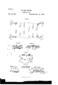
- Figure 1 represents a side elevation of a portion of a hoop-driving machine embodying my invention.
- Figs. 2, 3, and 4 represent, respectively, a section, front view,and bottom View of the hoop-driver.
- Fig. 5 represents a section of a portion of the barrel and hoop, showing the out behind the hoop.
- My invention consists, essentially, in hoopdrivers for hoop-driving machines, whereby the hoop is more securely fastened when driven.
- driver adjustable so that the depth of the chine may be regulated.
- A represents the arms of a hoop-driving machine, the same being of ordinary form and construction and properly connected to the machine.
- B represents a jaw or driver, which is connected with an arm, A, and formed with a head, a, a recess, 1), and cutting-edge c, anda cutting-edge, d, a number of said jaws being employed around a barrel, it being noticed that the head a is adapted to be brought in contact with the chine-hoop to be driven, and the recess 1) receives the chine of a barrel and permits the advance of the driver.
- the jaws are advanced, the hoop is properly driven on the barrel, and the edge 0 cuts into the wood behind the hoop, (see Fig. 5,) thus forcing the wood against the inner face of the hoop, serving to wedge the same and hold it firmly in position.
- the wall of the recess 1) becomes the driver,
- edge d cuts the Wood similarly to the edge 0.
- a jaw or driver having the head a, recess 11, and cutting-edge c all on the same face, the said out ting-edge being between the said head and the said recess, substantially as described.
- a hoop-driver composed of two parts secured together, one of the said parts having a cutting-edge 011 one of its faces, and the other part having a recess on the same face, substantially as described.
- a hoop-driver composed of two parts adjustably connected, each of said parts having a cutting-edge on one of its faces, and one of them having a recess on the same face as the cutting-edge, substantially as described.
- a hoop-driver composed of two parts,B and B the said part B having a drivinghead, a, and a cutting-edge, c, on the same face, and the part 13 having the recess 1) and the cutting-edge d on one of its faces, the said parts being adj ustab] y secured so that the said cutting-edges, head, and recess are on the same face of the said driver, substantially as described.
Landscapes
- Engineering & Computer Science (AREA)
- Life Sciences & Earth Sciences (AREA)
- Manufacturing & Machinery (AREA)
- Mechanical Engineering (AREA)
- Wood Science & Technology (AREA)
- Forests & Forestry (AREA)
- Portable Nailing Machines And Staplers (AREA)
Description
(No Model.)
M. NAUGHTON.
HOOP DRIVER. No. 328,706. Patented Oct. 20. 1885.
n PETERS. Phmo-Ulhognphar, wahmmn. o c.
MICHAEL N AUGHTON OF PHILADELPHIA, PENNSYLVANIA.
HOOP-DRIVER.
SPECIFICATION forming part of Letters Patent No. 328,706, dated October 20, 1885.
Application filed July 17, 1885. Serial No. 171,853. (No model.)
To all whom it may concern:
Be it known that I, MICHAEL N AUGHTON, a citizen ofthe United States, residing in the city and county of Philadelphia, State of Pennsylvania, have invented a new and useful Improvement in Hoop-Driving Machines, which improvement is fully set forth in the following specification and accompanying drawings, in which Figure 1 represents a side elevation of a portion of a hoop-driving machine embodying my invention. Figs. 2, 3, and 4 represent, respectively, a section, front view,and bottom View of the hoop-driver. Fig. 5 represents a section of a portion of the barrel and hoop, showing the out behind the hoop.
Similar letters of reference indicate corresponding parts in the several figures.
My invention consists, essentially, in hoopdrivers for hoop-driving machines, whereby the hoop is more securely fastened when driven.
It also consists in making the driver adjustable, so that the depth of the chine may be regulated.
Referring to the drawings, A represents the arms of a hoop-driving machine, the same being of ordinary form and construction and properly connected to the machine.
B represents a jaw or driver, which is connected with an arm, A, and formed with a head, a, a recess, 1), and cutting-edge c, anda cutting-edge, d, a number of said jaws being employed around a barrel, it being noticed that the head a is adapted to be brought in contact with the chine-hoop to be driven, and the recess 1) receives the chine of a barrel and permits the advance of the driver. \Vhen the jaws are advanced, the hoop is properly driven on the barrel, and the edge 0 cuts into the wood behind the hoop, (see Fig. 5,) thus forcing the wood against the inner face of the hoop, serving to wedge the same and hold it firmly in position. For driving bilge-hoops, the wall of the recess 1) becomes the driver,
and the edge d cuts the Wood similarly to the edge 0.
In order to adjust the length of the driver, or adjust the position of the head a and recess b and cutting-edges c d relatively to each other, I form the driver of two parts, B B and connect the same by a set-screw, one of the parts" having a screw threaded opening, and the other a slot, whereby the parts may be moved for the purposes of adjustment, and afterward securely connected as one, the screw employedbeing adapted to connect the driver With the arm.
Having thus described my invention, what I claim as new, and desire to secure by Letters Patent, is-
1. In a hoop driving machine, a jaw or driver having the head a, recess 11, and cutting-edge c all on the same face, the said out ting-edge being between the said head and the said recess, substantially as described.
2. A hoop-driver composed of two parts secured together, one of the said parts having a cutting-edge 011 one of its faces, and the other part having a recess on the same face, substantially as described.
3. A hoop-driver composed of two parts adjustably connected, each of said parts having a cutting-edge on one of its faces, and one of them having a recess on the same face as the cutting-edge, substantially as described.
4. A hoop-driver composed of two parts,B and B the said part B having a drivinghead, a, and a cutting-edge, c, on the same face, and the part 13 having the recess 1) and the cutting-edge d on one of its faces, the said parts being adj ustab] y secured so that the said cutting-edges, head, and recess are on the same face of the said driver, substantially as described.
MIOHA EL NAUGHTON.
WitnessesQ JOHN A. WIEDERSHEIM, A. P. GRANT.
Publications (1)
| Publication Number | Publication Date |
|---|---|
| US328706A true US328706A (en) | 1885-10-20 |
Family
ID=2397819
Family Applications (1)
| Application Number | Title | Priority Date | Filing Date |
|---|---|---|---|
| US328706D Expired - Lifetime US328706A (en) | Hoop-driver |
Country Status (1)
| Country | Link |
|---|---|
| US (1) | US328706A (en) |
-
0
- US US328706D patent/US328706A/en not_active Expired - Lifetime
Similar Documents
| Publication | Publication Date | Title |
|---|---|---|
| US328706A (en) | Hoop-driver | |
| US442878A (en) | Jacob geiger | |
| US369908A (en) | Cutting-tool gage | |
| US441758A (en) | Device for setting the edges of plane-bits | |
| US269315A (en) | Gutter-head | |
| US870971A (en) | Device for cutting key-seats or the like. | |
| US276417A (en) | Cutting-pliers | |
| US1342031A (en) | Tool-holder | |
| US1283761A (en) | Tool for forming grooves in plastic masonry. | |
| US996140A (en) | Cutting apparatus for paper-cutting machines. | |
| US522282A (en) | Chisel | |
| US1166277A (en) | Channeling-tool. | |
| US1376438A (en) | Inserted-tooth cutter-head and method of making the same | |
| US356429A (en) | Half to edmond g | |
| US508982A (en) | Channel-cutting tool for planing-machines | |
| US422517A (en) | Peters | |
| US1131538A (en) | Tool-holder. | |
| US257564A (en) | John w | |
| US863939A (en) | Channel-cutter. | |
| US570139A (en) | Edwin p | |
| US678776A (en) | Chisel-gage. | |
| US429973A (en) | Slicing-machine | |
| US354876A (en) | Device for cutting | |
| US475768A (en) | houghton | |
| US338695A (en) | Cutter-head |