US3277686A - Apparatus for obtaining improved finishes on double reduced material - Google Patents
Apparatus for obtaining improved finishes on double reduced material Download PDFInfo
- Publication number
- US3277686A US3277686A US419311A US41931164A US3277686A US 3277686 A US3277686 A US 3277686A US 419311 A US419311 A US 419311A US 41931164 A US41931164 A US 41931164A US 3277686 A US3277686 A US 3277686A
- Authority
- US
- United States
- Prior art keywords
- rolls
- water
- work
- roll
- work rolls
- Prior art date
- Legal status (The legal status is an assumption and is not a legal conclusion. Google has not performed a legal analysis and makes no representation as to the accuracy of the status listed.)
- Expired - Lifetime
Links
- 239000000463 material Substances 0.000 title description 18
- XLYOFNOQVPJJNP-UHFFFAOYSA-N water Substances O XLYOFNOQVPJJNP-UHFFFAOYSA-N 0.000 claims description 46
- 239000007921 spray Substances 0.000 claims description 25
- 239000000498 cooling water Substances 0.000 claims description 21
- 238000005097 cold rolling Methods 0.000 claims description 12
- 239000010687 lubricating oil Substances 0.000 claims description 9
- 239000003921 oil Substances 0.000 claims description 7
- 229910000831 Steel Inorganic materials 0.000 claims description 3
- 239000010959 steel Substances 0.000 claims description 3
- 235000006506 Brasenia schreberi Nutrition 0.000 description 14
- 244000267222 Brasenia schreberi Species 0.000 description 14
- ATJFFYVFTNAWJD-UHFFFAOYSA-N Tin Chemical compound [Sn] ATJFFYVFTNAWJD-UHFFFAOYSA-N 0.000 description 14
- 238000005096 rolling process Methods 0.000 description 14
- 230000009467 reduction Effects 0.000 description 9
- 235000014113 dietary fatty acids Nutrition 0.000 description 7
- 229930195729 fatty acid Natural products 0.000 description 7
- 239000000194 fatty acid Substances 0.000 description 7
- 150000004665 fatty acids Chemical class 0.000 description 7
- 239000011248 coating agent Substances 0.000 description 6
- 238000000576 coating method Methods 0.000 description 6
- 235000019198 oils Nutrition 0.000 description 6
- 239000000839 emulsion Substances 0.000 description 5
- 239000000314 lubricant Substances 0.000 description 5
- 239000010731 rolling oil Substances 0.000 description 5
- 235000019482 Palm oil Nutrition 0.000 description 4
- 125000005907 alkyl ester group Chemical group 0.000 description 4
- 238000000034 method Methods 0.000 description 4
- 239000002540 palm oil Substances 0.000 description 4
- 239000000047 product Substances 0.000 description 4
- 239000005028 tinplate Substances 0.000 description 4
- CWYNVVGOOAEACU-UHFFFAOYSA-N Fe2+ Chemical compound [Fe+2] CWYNVVGOOAEACU-UHFFFAOYSA-N 0.000 description 3
- 230000001050 lubricating effect Effects 0.000 description 3
- 239000002184 metal Substances 0.000 description 3
- 238000001816 cooling Methods 0.000 description 2
- 230000000694 effects Effects 0.000 description 2
- 238000005461 lubrication Methods 0.000 description 2
- 239000000203 mixture Substances 0.000 description 2
- 239000000126 substance Substances 0.000 description 2
- 230000032258 transport Effects 0.000 description 2
- 235000012431 wafers Nutrition 0.000 description 2
- 230000009471 action Effects 0.000 description 1
- 238000013019 agitation Methods 0.000 description 1
- 230000004075 alteration Effects 0.000 description 1
- 239000010953 base metal Substances 0.000 description 1
- 230000015556 catabolic process Effects 0.000 description 1
- 235000012343 cottonseed oil Nutrition 0.000 description 1
- 239000002385 cottonseed oil Substances 0.000 description 1
- 238000005520 cutting process Methods 0.000 description 1
- 239000010685 fatty oil Substances 0.000 description 1
- 239000012467 final product Substances 0.000 description 1
- 239000012530 fluid Substances 0.000 description 1
- 125000005456 glyceride group Chemical group 0.000 description 1
- 230000005484 gravity Effects 0.000 description 1
- 230000005012 migration Effects 0.000 description 1
- 238000013508 migration Methods 0.000 description 1
- 230000004048 modification Effects 0.000 description 1
- 238000012986 modification Methods 0.000 description 1
- 230000000737 periodic effect Effects 0.000 description 1
- 230000000704 physical effect Effects 0.000 description 1
- 230000000750 progressive effect Effects 0.000 description 1
- 238000005488 sandblasting Methods 0.000 description 1
- 239000003549 soybean oil Substances 0.000 description 1
- 235000012424 soybean oil Nutrition 0.000 description 1
- 238000010186 staining Methods 0.000 description 1
- 235000015112 vegetable and seed oil Nutrition 0.000 description 1
- 239000008158 vegetable oil Substances 0.000 description 1
- 235000013311 vegetables Nutrition 0.000 description 1
- 239000003643 water by type Substances 0.000 description 1
Images

Classifications
-
- B—PERFORMING OPERATIONS; TRANSPORTING
- B21—MECHANICAL METAL-WORKING WITHOUT ESSENTIALLY REMOVING MATERIAL; PUNCHING METAL
- B21B—ROLLING OF METAL
- B21B27/00—Rolls, roll alloys or roll fabrication; Lubricating, cooling or heating rolls while in use
- B21B27/06—Lubricating, cooling or heating rolls
- B21B27/10—Lubricating, cooling or heating rolls externally
-
- B—PERFORMING OPERATIONS; TRANSPORTING
- B21—MECHANICAL METAL-WORKING WITHOUT ESSENTIALLY REMOVING MATERIAL; PUNCHING METAL
- B21B—ROLLING OF METAL
- B21B45/00—Devices for surface or other treatment of work, specially combined with or arranged in, or specially adapted for use in connection with, metal-rolling mills
- B21B45/02—Devices for surface or other treatment of work, specially combined with or arranged in, or specially adapted for use in connection with, metal-rolling mills for lubricating, cooling, or cleaning
- B21B45/0239—Lubricating
- B21B45/0245—Lubricating devices
- B21B45/0248—Lubricating devices using liquid lubricants, e.g. for sections, for tubes
- B21B45/0251—Lubricating devices using liquid lubricants, e.g. for sections, for tubes for strips, sheets, or plates
-
- C—CHEMISTRY; METALLURGY
- C10—PETROLEUM, GAS OR COKE INDUSTRIES; TECHNICAL GASES CONTAINING CARBON MONOXIDE; FUELS; LUBRICANTS; PEAT
- C10M—LUBRICATING COMPOSITIONS; USE OF CHEMICAL SUBSTANCES EITHER ALONE OR AS LUBRICATING INGREDIENTS IN A LUBRICATING COMPOSITION
- C10M1/00—Liquid compositions essentially based on mineral lubricating oils or fatty oils; Their use as lubricants
- C10M1/08—Liquid compositions essentially based on mineral lubricating oils or fatty oils; Their use as lubricants with additives
-
- B—PERFORMING OPERATIONS; TRANSPORTING
- B21—MECHANICAL METAL-WORKING WITHOUT ESSENTIALLY REMOVING MATERIAL; PUNCHING METAL
- B21B—ROLLING OF METAL
- B21B1/00—Metal-rolling methods or mills for making semi-finished products of solid or profiled cross-section; Sequence of operations in milling trains; Layout of rolling-mill plant, e.g. grouping of stands; Succession of passes or of sectional pass alternations
- B21B1/22—Metal-rolling methods or mills for making semi-finished products of solid or profiled cross-section; Sequence of operations in milling trains; Layout of rolling-mill plant, e.g. grouping of stands; Succession of passes or of sectional pass alternations for rolling plates, strips, bands or sheets of indefinite length
- B21B1/227—Surface roughening or texturing
-
- B—PERFORMING OPERATIONS; TRANSPORTING
- B21—MECHANICAL METAL-WORKING WITHOUT ESSENTIALLY REMOVING MATERIAL; PUNCHING METAL
- B21B—ROLLING OF METAL
- B21B1/00—Metal-rolling methods or mills for making semi-finished products of solid or profiled cross-section; Sequence of operations in milling trains; Layout of rolling-mill plant, e.g. grouping of stands; Succession of passes or of sectional pass alternations
- B21B1/38—Metal-rolling methods or mills for making semi-finished products of solid or profiled cross-section; Sequence of operations in milling trains; Layout of rolling-mill plant, e.g. grouping of stands; Succession of passes or of sectional pass alternations for rolling sheets of limited length, e.g. folded sheets, superimposed sheets, pack rolling
- B21B2001/383—Cladded or coated products
-
- B—PERFORMING OPERATIONS; TRANSPORTING
- B21—MECHANICAL METAL-WORKING WITHOUT ESSENTIALLY REMOVING MATERIAL; PUNCHING METAL
- B21B—ROLLING OF METAL
- B21B27/00—Rolls, roll alloys or roll fabrication; Lubricating, cooling or heating rolls while in use
- B21B27/06—Lubricating, cooling or heating rolls
- B21B27/10—Lubricating, cooling or heating rolls externally
- B21B2027/103—Lubricating, cooling or heating rolls externally cooling externally
-
- B—PERFORMING OPERATIONS; TRANSPORTING
- B21—MECHANICAL METAL-WORKING WITHOUT ESSENTIALLY REMOVING MATERIAL; PUNCHING METAL
- B21B—ROLLING OF METAL
- B21B27/00—Rolls, roll alloys or roll fabrication; Lubricating, cooling or heating rolls while in use
- B21B27/02—Shape or construction of rolls
-
- B—PERFORMING OPERATIONS; TRANSPORTING
- B21—MECHANICAL METAL-WORKING WITHOUT ESSENTIALLY REMOVING MATERIAL; PUNCHING METAL
- B21B—ROLLING OF METAL
- B21B45/00—Devices for surface or other treatment of work, specially combined with or arranged in, or specially adapted for use in connection with, metal-rolling mills
- B21B45/02—Devices for surface or other treatment of work, specially combined with or arranged in, or specially adapted for use in connection with, metal-rolling mills for lubricating, cooling, or cleaning
- B21B45/0239—Lubricating
- B21B45/0242—Lubricants
-
- C—CHEMISTRY; METALLURGY
- C10—PETROLEUM, GAS OR COKE INDUSTRIES; TECHNICAL GASES CONTAINING CARBON MONOXIDE; FUELS; LUBRICANTS; PEAT
- C10M—LUBRICATING COMPOSITIONS; USE OF CHEMICAL SUBSTANCES EITHER ALONE OR AS LUBRICATING INGREDIENTS IN A LUBRICATING COMPOSITION
- C10M2207/00—Organic non-macromolecular hydrocarbon compounds containing hydrogen, carbon and oxygen as ingredients in lubricant compositions
- C10M2207/28—Esters
- C10M2207/281—Esters of (cyclo)aliphatic monocarboxylic acids
-
- C—CHEMISTRY; METALLURGY
- C10—PETROLEUM, GAS OR COKE INDUSTRIES; TECHNICAL GASES CONTAINING CARBON MONOXIDE; FUELS; LUBRICANTS; PEAT
- C10M—LUBRICATING COMPOSITIONS; USE OF CHEMICAL SUBSTANCES EITHER ALONE OR AS LUBRICATING INGREDIENTS IN A LUBRICATING COMPOSITION
- C10M2207/00—Organic non-macromolecular hydrocarbon compounds containing hydrogen, carbon and oxygen as ingredients in lubricant compositions
- C10M2207/28—Esters
- C10M2207/282—Esters of (cyclo)aliphatic oolycarboxylic acids
-
- C—CHEMISTRY; METALLURGY
- C10—PETROLEUM, GAS OR COKE INDUSTRIES; TECHNICAL GASES CONTAINING CARBON MONOXIDE; FUELS; LUBRICANTS; PEAT
- C10M—LUBRICATING COMPOSITIONS; USE OF CHEMICAL SUBSTANCES EITHER ALONE OR AS LUBRICATING INGREDIENTS IN A LUBRICATING COMPOSITION
- C10M2207/00—Organic non-macromolecular hydrocarbon compounds containing hydrogen, carbon and oxygen as ingredients in lubricant compositions
- C10M2207/28—Esters
- C10M2207/283—Esters of polyhydroxy compounds
-
- C—CHEMISTRY; METALLURGY
- C10—PETROLEUM, GAS OR COKE INDUSTRIES; TECHNICAL GASES CONTAINING CARBON MONOXIDE; FUELS; LUBRICANTS; PEAT
- C10M—LUBRICATING COMPOSITIONS; USE OF CHEMICAL SUBSTANCES EITHER ALONE OR AS LUBRICATING INGREDIENTS IN A LUBRICATING COMPOSITION
- C10M2207/00—Organic non-macromolecular hydrocarbon compounds containing hydrogen, carbon and oxygen as ingredients in lubricant compositions
- C10M2207/28—Esters
- C10M2207/286—Esters of polymerised unsaturated acids
-
- C—CHEMISTRY; METALLURGY
- C10—PETROLEUM, GAS OR COKE INDUSTRIES; TECHNICAL GASES CONTAINING CARBON MONOXIDE; FUELS; LUBRICANTS; PEAT
- C10M—LUBRICATING COMPOSITIONS; USE OF CHEMICAL SUBSTANCES EITHER ALONE OR AS LUBRICATING INGREDIENTS IN A LUBRICATING COMPOSITION
- C10M2207/00—Organic non-macromolecular hydrocarbon compounds containing hydrogen, carbon and oxygen as ingredients in lubricant compositions
- C10M2207/40—Fatty vegetable or animal oils
- C10M2207/404—Fatty vegetable or animal oils obtained from genetically modified species
Definitions
- the present invention relates to means for producing very thin tin-coated ferrous sheet and strip material. More particulaly the present invention relates to novel apparatus for providing a superior surface finish upon very thin tin-coated ferrous sheet and strip material.
- tin plate and strip Users of tin plate and strip, especially can manufacturers, are very demanding with respect to the surface finish of the product and particularly with respect to uniformity of finish.
- users of tin-coated products also desire various degrees of brightness of surface on the strip and sheet which they purchase.
- Cold reduction by rolling is usually conducted with a lubricating or rolling oil to prevent sticking of the metal to the roll surface and to reduce the horizontal friction factor so that reduction is more easily accomplished.
- Modern practice has almost universally been to form an emulsion of the lubricating oil and cooling water and apply the emulsion to the strip entering the roll bite. It has been thought that the rolling oil and water emulsion acts as a unitary and homogeneous fluid medium for both cooling and lubricating the rolling operation.
- the present inventors have discovered that it is free water in the roll bite which causes the mottling of double reduced tin coated strip material.
- the conventional oil and water emulsion tends to break down, especially when subjected to the heat and pressure of the roll bite. No practical method is known to prevent this breakdown as the stable emulsion point is very critical.
- the inventors have discovered, however, that if the reduction of the already coated strip is carried out in a uniform lubricating oil medium consisting only of oil or of well mixed oil mediums which are thoroughly miscible with each other the mottled surfaces are eliminated. Furthermore, they have discovered that if the rolling is carried out with the correct lubricating regardless of changes in mlll speed, roll temperatures and roll finishes, or surface conditions of material entering the mill.
- the inventors apply cooling water to the rear of the work rolls and provide means to prevent the cooling water from reaching the entrance side of the work rolls where it could enter the roll bite.
- These means include the use of special splash shields in combination with a novel matching of the work surfaces of the work rolls and the back-up rolls.
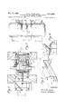
- FIGURE 1 shows in section an elevation of a rolling mill arranged according to the present invention.
- FIGURE 2 shows a section in plan of FIGURE 1 along line 22 with top back-up roll and top water shield flaps removed.
- FIGURE 3 illustrates the conformation of the surface of the work rolls and the arrangement of the work rolls and the back-up rolls.
- FIGURE 4 shows in expanded view the ends of the work rolls and the back-up rolls of the present invention.
- FIGURE 5 is an isometric view of the entry water shield.
- FIGURES 1 and 2 A section of a roll stand 12 is shown in outline in FIGURES 1 and 2.
- Back-up rolls 14 and 16 mounted in stand 12 are shown in section in FIGURE 1.
- rolls 18 and 20 are shown in section between back-up rolls 14 and 16.
- Tin coated strip 22 is fed from a coil of '5 so as to eliminate a sharp edge along this side which might mar the bottom of strip 22 if it should touch plate 42
- At the rear of the bottom plate 42 of both water shields 36 and 38 are secured clamp members 46 having arm members 47.
- entry water shields 36 and 38 may be placed in position on both sides of strip 22 by sliding the shields 36 and 38 across cross member 48 of roll stand 12 until the arm members 47 of the clamps 46 engage the underside of member 48.
- Screw clamps may be passed through arm members 47 from the bottom if desired to engage cross member 48 to lock the two members 46 and 48 together more securely.
- shields 36 and 38 as shown in FIGURES l and 2 are positioned with their bottom plates under and very near but not touc 'ng the lower surface of the strip 22 passing to the bite of the work rolls while their side plates 40 are closely adjacent the sides of the strip and their inclined top plates 44 are located over but spaced considerably away from the strip surface.
- water shield flaps 50, 52, 54 not shown, and 56 are pivoted on shafts 50a, 52a, 54a, not shown, and 56a supported by the mill stand structure 12 as shown in FIGURES 1 and 2.
- Water shield flaps 50, 52, 54 and 56 are arranged somewhat outwardly of the sides 40 of water shields 36 and 38 to more effectively shield the roll bite and the strip entering the roll bite from any splashed water. It will be noted that water shield flaps 50, 52, 54 and 56 are obviouslycuately concave in two unequal sized arcs toward the mill rolls and are positioned adjacent the rolls in order to close the spaces between the reducing and back-up rolls.
- top water spray nozzles 58 and bottom water spray nozzles 60 Positioned on the exit side of work rolls 18 and 20 are top water spray nozzles 58 and bottom water spray nozzles 60 which spray cooling water on the exit sides of work rolls 18 and 20 respectively.
- Top water sprays 58 are mounted upon a so-called water scoop 62 which comprises a trough-like structure extending along the rear of the work rolls having a water wiper 64 mounted upon its lower section to bear against the work surface of the work roll 18.
- Water wiper 64 may be com-posed of some flexible material and is designed to provide a water seal against the surface of roll 18 so that substantially no water will pass from the area on top of wiper 64 to the area adjacent the bottom.
- the cooling water discharged against the surface of roll 18 by spray nozzles 58 runs down the roll surface to wiper 64 which wipes the water from the surface and directs it into water scoop 62, which collects the considerable volume of water and discharges it from the open ends of scoop 62 beyond the edges of strip 22 where is can fall into a sump, not shown, under the mill stand.
- Water scoop 62 and its associated water wiper 64 are actively pressed against the back of work roll 18 by the action of air cylinder 66.
- Air cylinder 66 also may be operated to retract scoop 62 and wiper 64 out of the way when changing the rolls in stand 12.
- Bottom water spray nozzles 60 discharge their cooling water against the rear of bottom work roll 20 where both because of the effects of gravity and because work roll 20 is turning in the direction shown by the arrows in FIGURE 1, the water flows downwardly away from strip 22 and eventually into the sump, not shown, under the mill. A water scoop such as 62 is thus unnecessary to prevent the spray from bottom cooling nozzles 60 from contacting the strip 22.
- a film of water from both groups of spray nozzles 58 and 60 is carried on work rolls 18 and 20 respectively, on the surface thereof to the areas of contact between the said work rolls and their respective back-up rolls 14 and 16. Because of the very high pressure and close contact between the work rolls and back-up rolls water cannot pass between these rolls but is instead squeezed out and forced along the rolls to the sides thereof where it drains away. It is important that the surfaces of the back-up and work rolls be smooth and free from any imperfections or scuff marks which might allow water to pass between the rolls.
- FIGURES 3 and 4 This structural relationship is shown in FIGURES 3 and 4 where the work surfaces 68 and 70 of work rolls 18 and 20 respectively have been cut back at 72 providing a sharp shoulder at 74 exactly opposite the edge 76 of the bevel surface 78 on back-up rolls 14 and 16.
- Work rolls 18 and 20 are beveled at 80.
- Cut 72 may initially be formed about one-eighth of an inch deep so that as the rolls are subsequently reground the cut will remain at least one thirty-second of an inch deep.
- One thirty-sec- 0nd of an inch is approximately the minimum desirable. However the cut may be made deeper than one-eighth inch initially if desired. It may be clearly seen in FIG- URE 4 that the cut back surface 72 of work roll 18 is opposite.
- fatty acid it should be understood that the substances referred to are the fatty acids having suitable rolling lubrication properties, i.e., in general those fatty acids containing from 6 to 22 carbons.
- suitable rolling lubrication properties i.e., in general those fatty acids containing from 6 to 22 carbons.
- suitable fatty oils such as oils of animal or vegetable origin may also be used.
- alkyl esters of fatty acids may be mixed with these rolling oils in various proportions depending upon how bright a surface is desired. Alkyl esters of fatty acids are completely miscible with these rolling oils so that a homogeneous lubricant is obtained. Any suitable commercial chemical proportioning equipment may be used to correctly mix and proportion the rolling oil and alkyl esters.
- the coil is placed on feed reel 24, and the end of the strip is threaded through work rolls 18 and 20, past rolls 28 and 29, and secured to takeup or tension reel 30.
- oil e.g., palm oil
- sprays 32 and 34 Prior to its entry into the roll bite.
- cooling Water is sprayed onto the work rolls by means of water sprays 58 and 60.
- the work rolls and the tension on the strip are adjusted to effect a reduction of the strip gauge of 40%.
- the resultant product is a thin tin plated strip having a moderately dull but uniform textured surface, suitable for the majority of uses to which thin tin plate can be put.
- the present invention provides a very practical and reliable method and means for obtaining even textured double reduced strip material in a single cold rolling stand without the use of any expensive or complicated special equipment.
- a rolling mill stand for cold rolling of tin coated steel strip said rolling mill stand having two back-up rolls provided with central working surfaces and beveled ends, two work rolls having central working surfaces of the same width as those of the back-up rolls terminating in sharp corners and cut back portions in line with and contacting the inner edges of the bevels on the back-up rolls, oil sprays on the entry side of the work rolls to spray water-free lubricating oil on the strip entering the roll bite, water sprays on the exit side of the Work rolls to spray cooling water on the rear of the reducing rolls, a trough having a wiper blade in contact with the upper work roll below the water sprays for said roll to prevent cooling water from running into the roll bite on the exit side and water shields on the entry side of the mill closely adjacent to the work rolls and back-up rolls to prevent water from splashing from the exit side to the entrance side of the mill.
- Apparatus for cold rolling metallic strip comprising work rolls having work surfaces terminating in sharp cornered shoulders, back-up rolls having Work surfaces terminating in beveled ends, the shoulders on the Work rolls being in alignment with the inner edges of the beveled end portions of the back-up rolls, upper and lower water spray means directed at the exit side of the work rolls, a water wiper and an associated trough located adjacent the exit side of the upper work roll, with the wiper in contact with said roll to remove and trans port water from the rear surface of said upper work roll, and means to prevent splashing of Water from the exit side to the entrance side of the rolls and on to the mate rial entering the roll bite comprising two splash shields, mounted adjacent the sides of the strip, having portions extending partly over and partly under each side of the strip adjacent the roll bite,-and four splash shields mounted outboard of the two first mentioned shields, each of said four shields mounted adjacent to and extending into the bite between the work rollsand adjacent back-up rolls and having arcuate edges conforming with the contours of said rolls.
- Apparatus for cold rolling metallic strip comprising:
- splash shield means substantially vertically disposed, adjacent the edges of the entering strip, and extending into the bite between the Work rolls and adjacent back-up rolls.
- a four-high cold rolling mill comprising:
- splash shield means to prevent any cooling water from splashing from the exit side of the work rolls to the entrance area of the Work rolls.
- Apparatus for cold rolling metallic strip comprising:
- splash shield means to prevent cooling water from splashing from the exit side of the Work rolls to the entrance area of the Work rolls.
- Apparatus for cold rolling metallic strip comprising:
- (f) means to prevent cooling water from splashing from the exit side of the work rolls to the entrance area of the work rolls.
- Apparatus for cold rolling metallic strip comprising:
- first splash shield means mounted on either side of and partly over and under the strip adjacent the roll bite
Landscapes
- Engineering & Computer Science (AREA)
- Chemical & Material Sciences (AREA)
- Mechanical Engineering (AREA)
- Oil, Petroleum & Natural Gas (AREA)
- Chemical Kinetics & Catalysis (AREA)
- General Chemical & Material Sciences (AREA)
- Organic Chemistry (AREA)
- Metal Rolling (AREA)
Description
Oct. 11, 1966 Q w JAMES ETAL 3,277,686
APPARATUS FOR OBTAINING IMPROVED FINISHES ON DOUBLE REDUCED MATERIAL Original Filed June 26, 1961 2 Sheets-Sheet l lNVE/V TORS Owen 14 James fuyene Wafers o. w. JAMES ETAL 3,277,686 APPARATUS FOR OBTAINING IMPROVED FINISHES ON DOUBLE REDUCED MATERIAL 1961 Oct. 11, 1966 2 Sheets-Sheet 2 Original Filed June 26,
' l/VVEA/TORS Owen M/. James fqqene R Wafers United States Patent 0 3,277,686 APPARATUS FOR OBTAINING IMPROVED FIN- ISI-IES 0N DOUBLE REDUCED MATERIAL Owen W. James and Eugene P. Waters, Baltimore, Md., assignors, by mesne assignments, to Bethlehem Steel Corporation, a corporation of Delaware Original application June 26, 1961, Ser. No. 124,889, now Patent No. 3,200,629, dated Aug. 17, 1965. Divided and this application Dec. 18, 1964, Ser. No. 419,311 7 Claims. (Cl. 72-201) This is a division of application Serial No. 124,889, filed June 26, 1961, nowPatent No. 3,200,629.
The present invention relates to means for producing very thin tin-coated ferrous sheet and strip material. More particulaly the present invention relates to novel apparatus for providing a superior surface finish upon very thin tin-coated ferrous sheet and strip material.
Recently very thin tin-coated strip has been produced by rolling steel strip in conventional fashion, coating the strip with tin according to normal practice and then finally passing the coated strip through a second cold rolling operation which reduces the strip and its coating to a still lighter gauge. Although the tin coating is softer than the ferrous base, both the coating and the base metal are reduced approximately proportionally. Reductions may be made to almost any reasonable extent. However, the normal reduction is usually from 35 to 50%. Thin coated strip material produced according to this method is known as double reduced material since it has been passed through two series of reducing operations.
While double reduction produces excellent thin tin- ,coated strip material possessing very satisfactory physical properties, trouble has been experienced with the surface finish due to roll marks, staining and particularly mottling of the surface.
Users of tin plate and strip, especially can manufacturers, are very demanding with respect to the surface finish of the product and particularly with respect to uniformity of finish. In addition, users of tin-coated products also desire various degrees of brightness of surface on the strip and sheet which they purchase.
Heretofore the mottled and uneven surface finishes on double reduced material have been covered up by passing the double reduced material through a skin pass rolling stand between rolls which have been roughened by some expedient such as sand blasting. This operation breaks up the surface and results in a comparatively rough or coarse finish which more or less hides the underlying mottling. This solution of the problem is not satisfactory, however, because the mottling is not completely hidden, many purchasers of tin coated product do not desire a coarse finish, and the roughened skin pass rolling operation adds an extra step to the double reduction operation.
The cold rolling of metal produces considerable heat as a result of the work done in reducing the metal. This heat must be removed to prevent a progressive alteration in the size and shape of the roll pass due to gradual expansion of the rolls as the heat builds up. Conventional practice is to flood the rolls with cooling water to remove the heat.
Cold reduction by rolling is usually conducted with a lubricating or rolling oil to prevent sticking of the metal to the roll surface and to reduce the horizontal friction factor so that reduction is more easily accomplished. Modern practice has almost universally been to form an emulsion of the lubricating oil and cooling water and apply the emulsion to the strip entering the roll bite. It has been thought that the rolling oil and water emulsion acts as a unitary and homogeneous fluid medium for both cooling and lubricating the rolling operation.
The present inventors have discovered that it is free water in the roll bite which causes the mottling of double reduced tin coated strip material. In particular they have found that the conventional oil and water emulsion tends to break down, especially when subjected to the heat and pressure of the roll bite. No practical method is known to prevent this breakdown as the stable emulsion point is very critical. The inventors have discovered, however, that if the reduction of the already coated strip is carried out in a uniform lubricating oil medium consisting only of oil or of well mixed oil mediums which are thoroughly miscible with each other the mottled surfaces are eliminated. Furthermore, they have discovered that if the rolling is carried out with the correct lubricating regardless of changes in mlll speed, roll temperatures and roll finishes, or surface conditions of material entering the mill.
In order to cool the work rolls, the inventors apply cooling water to the rear of the work rolls and provide means to prevent the cooling water from reaching the entrance side of the work rolls where it could enter the roll bite. These means include the use of special splash shields in combination with a novel matching of the work surfaces of the work rolls and the back-up rolls.
It is an object of the present invention to provide rolling mill apparatus adapted to provide oil lubrication on the exit side of the work rolls and to prevent water from reaching the entrance side of the work rolls.
It is a still further object of the present invention to provide a work roll and back-up roll combination which Will prevent the migration of water films from the exit to the entrance side of the work rolls.
These and other objects and advantages will be recstruct-ures and in which:
FIGURE 1 shows in section an elevation of a rolling mill arranged according to the present invention.
FIGURE 2 shows a section in plan of FIGURE 1 along line 22 with top back-up roll and top water shield flaps removed.
FIGURE 3 illustrates the conformation of the surface of the work rolls and the arrangement of the work rolls and the back-up rolls.
FIGURE 4 shows in expanded view the ends of the work rolls and the back-up rolls of the present invention.
FIGURE 5 is an isometric view of the entry water shield.
A section of a roll stand 12 is shown in outline in FIGURES 1 and 2. Back-up rolls 14 and 16 mounted in stand 12 are shown in section in FIGURE 1. rolls 18 and 20 are shown in section between back-up rolls 14 and 16. Tin coated strip 22 is fed from a coil of '5 so as to eliminate a sharp edge along this side which might mar the bottom of strip 22 if it should touch plate 42 At the rear of the bottom plate 42 of both water shields 36 and 38 are secured clamp members 46 having arm members 47. As may be seen in FIGURES 1 and 2 entry water shields 36 and 38 may be placed in position on both sides of strip 22 by sliding the shields 36 and 38 across cross member 48 of roll stand 12 until the arm members 47 of the clamps 46 engage the underside of member 48. Screw clamps, not shown, may be passed through arm members 47 from the bottom if desired to engage cross member 48 to lock the two members 46 and 48 together more securely. During operation of the roll stand, shields 36 and 38, as shown in FIGURES l and 2, are positioned with their bottom plates under and very near but not touc 'ng the lower surface of the strip 22 passing to the bite of the work rolls while their side plates 40 are closely adjacent the sides of the strip and their inclined top plates 44 are located over but spaced considerably away from the strip surface. In order to facilitate drainage of any splashed water from shield-s 36 and 38, it is preferable that they be tipped rearwardly towards clamps 46 so that moisture will not drip from bevel 43 onto the lower work roll. Four water shield flaps 50, 52, 54 not shown, and 56 are pivoted on shafts 50a, 52a, 54a, not shown, and 56a supported by the mill stand structure 12 as shown in FIGURES 1 and 2. Water shield flaps 50, 52, 54 and 56 are arranged somewhat outwardly of the sides 40 of water shields 36 and 38 to more effectively shield the roll bite and the strip entering the roll bite from any splashed water. It will be noted that water shield flaps 50, 52, 54 and 56 are iarcuately concave in two unequal sized arcs toward the mill rolls and are positioned adjacent the rolls in order to close the spaces between the reducing and back-up rolls.
Positioned on the exit side of work rolls 18 and 20 are top water spray nozzles 58 and bottom water spray nozzles 60 which spray cooling water on the exit sides of work rolls 18 and 20 respectively. Top water sprays 58 are mounted upon a so-called water scoop 62 which comprises a trough-like structure extending along the rear of the work rolls having a water wiper 64 mounted upon its lower section to bear against the work surface of the work roll 18. Water wiper 64 may be com-posed of some flexible material and is designed to provide a water seal against the surface of roll 18 so that substantially no water will pass from the area on top of wiper 64 to the area adjacent the bottom. The cooling water discharged against the surface of roll 18 by spray nozzles 58 runs down the roll surface to wiper 64 which wipes the water from the surface and directs it into water scoop 62, which collects the considerable volume of water and discharges it from the open ends of scoop 62 beyond the edges of strip 22 where is can fall into a sump, not shown, under the mill stand. Water scoop 62 and its associated water wiper 64 are actively pressed against the back of work roll 18 by the action of air cylinder 66. Air cylinder 66 also may be operated to retract scoop 62 and wiper 64 out of the way when changing the rolls in stand 12. Bottom water spray nozzles 60 discharge their cooling water against the rear of bottom work roll 20 where both because of the effects of gravity and because work roll 20 is turning in the direction shown by the arrows in FIGURE 1, the water flows downwardly away from strip 22 and eventually into the sump, not shown, under the mill. A water scoop such as 62 is thus unnecessary to prevent the spray from bottom cooling nozzles 60 from contacting the strip 22.
A film of water from both groups of spray nozzles 58 and 60 is carried on work rolls 18 and 20 respectively, on the surface thereof to the areas of contact between the said work rolls and their respective back-up rolls 14 and 16. Because of the very high pressure and close contact between the work rolls and back-up rolls water cannot pass between these rolls but is instead squeezed out and forced along the rolls to the sides thereof where it drains away. It is important that the surfaces of the back-up and work rolls be smooth and free from any imperfections or scuff marks which might allow water to pass between the rolls.
There is considerable agitation and violent splashing of water to the rear of the rolls but splash water shields 36 and 38 and water shield flaps 50, 52, 54 and 56 effectively shield strip 22 near the entrance side of rolls 18 and 20, and also shield the work surface of the entrance side of the work rolls 18 and 20 themselves from any water which may be splashed or thrown from the exit side of the mill. Water shields 36 and 38 are mounted on clamps and water shield flaps 50, 52, 54 and 56 are pivotally mounted so that they can be removed or swung clear during the periodic changing of the rolls.
While the back-up rolls 14 and 14 effectively squeeze the cooling water from the surface of the rotating work rolls and the various water shields described above effectively prevent any water droplets from splashing from the area contacted by the cooling water to the entering strip or the roll bite of the mill, it has been found that water may still work its way around from the exit side of the work rolls to the work surface on the entrance side of the work rolls. The inventors prevent this by beveling the ends of the back-up rolls and by cutting shoulders on the ends of the Work rolls directly opposite the inner ends of the bevels on the back-up rolls. This structural relationship is shown in FIGURES 3 and 4 where the work surfaces 68 and 70 of work rolls 18 and 20 respectively have been cut back at 72 providing a sharp shoulder at 74 exactly opposite the edge 76 of the bevel surface 78 on back-up rolls 14 and 16. Work rolls 18 and 20 are beveled at 80. Cut 72 may initially be formed about one-eighth of an inch deep so that as the rolls are subsequently reground the cut will remain at least one thirty-second of an inch deep. One thirty-sec- 0nd of an inch is approximately the minimum desirable. However the cut may be made deeper than one-eighth inch initially if desired. It may be clearly seen in FIG- URE 4 that the cut back surface 72 of work roll 18 is opposite. the beveled surface 78 of back-up roll 14 with the edge 76 of bevel surface 78 of back-up rolls 14 exactly in line with and meeting the edge of shoulder 74 between the work surface 68 and the cut back surface 72 of work roll 18. The exact dimensions of the bevels on both the back-up and the work rolls and the cut back portions on the work rolls are not critical. It will be understood, however, that shoulder 74 is preferably substantially a sharp shoulder and the edge of this shoulder and the bevel edge 76 must be substantially exactly in line with each other. 7
While the foregoing is the inventors preferred embodiment and is particularly effective other configurations of rolls can be used, the most important consideration being that the working surfaces of the work rolls and back-up rolls be maintained of equal length and in exact alignment with each other.
It is particularly important in the cold rolling of coated materials to provide the correct rolling lubricant.
It has been found that excellent even textured so-called matte surfaces or dull surface finishes can be obtained by using a glyceride of a fatty acid as the lubricant on the entry side of the mill. By fatty acid it should be understood that the substances referred to are the fatty acids having suitable rolling lubrication properties, i.e., in general those fatty acids containing from 6 to 22 carbons. For example, pure palm oil or other comparable vegetable oil such as cottonseed oil or soybean oil constitute satisfactory lubricants. Other suitable fatty oils such as oils of animal or vegetable origin may also be used. If a brighter but also even textured surface finish is desired alkyl esters of fatty acids may be mixed with these rolling oils in various proportions depending upon how bright a surface is desired. Alkyl esters of fatty acids are completely miscible with these rolling oils so that a homogeneous lubricant is obtained. Any suitable commercial chemical proportioning equipment may be used to correctly mix and proportion the rolling oil and alkyl esters.
As an example of our invention, we start with a coil of tinplate produced in the usual manner on an electrolytic tinning line. The tin coating on the tinplate is heavier than that desired in the final product, in order to allow for reduction of the tin coating in the final rolling operation.
The coil is placed on feed reel 24, and the end of the strip is threaded through work rolls 18 and 20, past rolls 28 and 29, and secured to takeup or tension reel 30. As the rolling operation is started, oile.g., palm oil, is sprayed onto the upper and lower sides of strip 22 by means of sprays 32 and 34 prior to its entry into the roll bite. On the rear or exit side of the rolls, cooling Water is sprayed onto the work rolls by means of water sprays 58 and 60. The work rolls and the tension on the strip are adjusted to effect a reduction of the strip gauge of 40%. The resultant product is a thin tin plated strip having a moderately dull but uniform textured surface, suitable for the majority of uses to which thin tin plate can be put.
In producing strip on which a much brighter surface was desired, we followed the same procedure as given above except that instead of using palm oil alone as the lubricant we used a mixture of 80% palm oil and 20% alkyl esters of fatty acids.
It will be recognized that the present invention provides a very practical and reliable method and means for obtaining even textured double reduced strip material in a single cold rolling stand without the use of any expensive or complicated special equipment.
Although the present invention has been described here in in considerable detail, it should not be limited narrowly to the exact and specific particulars disclosed and/or described but may also include such substitutes, modifications or equivalents as are included within the scope and spirit of the invention or pointed out in the appended claims.
We claim:
1. A rolling mill stand for cold rolling of tin coated steel strip, said rolling mill stand having two back-up rolls provided with central working surfaces and beveled ends, two work rolls having central working surfaces of the same width as those of the back-up rolls terminating in sharp corners and cut back portions in line with and contacting the inner edges of the bevels on the back-up rolls, oil sprays on the entry side of the work rolls to spray water-free lubricating oil on the strip entering the roll bite, water sprays on the exit side of the Work rolls to spray cooling water on the rear of the reducing rolls, a trough having a wiper blade in contact with the upper work roll below the water sprays for said roll to prevent cooling water from running into the roll bite on the exit side and water shields on the entry side of the mill closely adjacent to the work rolls and back-up rolls to prevent water from splashing from the exit side to the entrance side of the mill.
2. Apparatus for cold rolling metallic strip comprising work rolls having work surfaces terminating in sharp cornered shoulders, back-up rolls having Work surfaces terminating in beveled ends, the shoulders on the Work rolls being in alignment with the inner edges of the beveled end portions of the back-up rolls, upper and lower water spray means directed at the exit side of the work rolls, a water wiper and an associated trough located adjacent the exit side of the upper work roll, with the wiper in contact with said roll to remove and trans port water from the rear surface of said upper work roll, and means to prevent splashing of Water from the exit side to the entrance side of the rolls and on to the mate rial entering the roll bite comprising two splash shields, mounted adjacent the sides of the strip, having portions extending partly over and partly under each side of the strip adjacent the roll bite,-and four splash shields mounted outboard of the two first mentioned shields, each of said four shields mounted adjacent to and extending into the bite between the work rollsand adjacent back-up rolls and having arcuate edges conforming with the contours of said rolls.
3. Apparatus for cold rolling metallic strip comprising:
(a) work rolls having work surfaces terminating in sharp cornered shoulders,
(b) back-up rolls having work surfaces terminating in bevelled ends, the shoulders on the work rolls being in alignment with the inner edges of the bevelled end portions of the back-up rolls,
(c) water spray means directed at least at the exit side of the upper work roll,
(d) a water wiper and an associated trough located adjacent the exit side of the upper work roll with the wiper in contact with said roll to remove and transport water from the rear surface of said upper Work roll, and
(e) means to prevent splashing of water from the exit side to the entrance side of the rolls and onto the material entering the roll bite comprising splash shield means substantially vertically disposed, adjacent the edges of the entering strip, and extending into the bite between the Work rolls and adjacent back-up rolls.
4. A four-high cold rolling mill comprising:
(a) a pair of back-up rolls having bevelled ends,
(b) a pair of Work rolls having sharp cornered shoulders aligned with the inner ends of the bevels on said back-up rolls and having portions of reduced diameter outboard of said shoulders,
(c) spray means for applying water free lubricating oil to the entrance area of the work rolls,
(d) spray means for applying cooling water to the exit side of the work rolls, and
(e) splash shield means to prevent any cooling water from splashing from the exit side of the work rolls to the entrance area of the Work rolls.
5. Apparatus for cold rolling metallic strip comprising:
(a) work rolls having work surfaces terminating in sharp cornered shoulders at least of an inch deep,
(b) back-up rolls having work surfaces terminating in bevelled ends,
(0) the shoulders on the work rolls being in alignment with the inner edges of the bevelled end portions of the back-up rolls,
(d) means for applying lubricating oil tothe entrance area of the work rolls,
(e) means for applying cooling water to the exit side of the work rolls,
(f) splash shield means to prevent cooling water from splashing from the exit side of the Work rolls to the entrance area of the Work rolls.
6. Apparatus for cold rolling metallic strip comprising:
(a) work rolls having work surfaces terminating in sharp cornered shoulders,
(b) back-up rolls having work surfaces terminating in recessed ends,
(c) the work surfaces on work rolls being in exact alignment with the contact surfaces of the back-up rolls,
(d) means for applying lubricating oil to the entrance area of the work rolls,
(e) means for applying cooling water to the exit side of the work rolls, and
(f) means to prevent cooling water from splashing from the exit side of the work rolls to the entrance area of the work rolls.
7. Apparatus for cold rolling metallic strip comprising:
(a) work rolls having work surfaces terminating in sharp cornered shoulders,
(b) back-up rolls having surfaces terminating in bevelled ends,
(c) the work surfaces on the work rolls being in exact alignment and coextensive with the contact surfaces of the back-up rolls,
(d) spray means for applying lubricating oil to the entrance area of the work rolls,
(e) spray means for applying cooling water to the exit side of the work rolls,
(f) first splash shield means mounted on either side of and partly over and under the strip adjacent the roll bite, and
(g) second splash shield means mounted outboard of and above and below the first shield means with extensions extending partially into the roll bite.
References Cited by the Examiner UNITED STATES PATENTS 161,786 4/1875 Harris et a1 72--201 1,963,539 6/ 1934 Zuber 72201 1,978,895 10/1934 Clark 72201 1,988,679 1/1935 Badlam 72201 2,017,403 10/1935 Lorig et al. 7245 2,344,996 3/1944 McConnell 72243 CHARLES W. LANHAM, Primary Examiner. H. D. HOINKES, Assistant Examiner.
Claims (1)
1. A ROLLING MILL STAND FOR COLD ROLLING OF TIN COATED STEEL STRIP, SAID ROLLING MILL STAND HAVING TWO BACK-UP ROLLS PROVIDED WITH CENTRAL WORKING SURFACES AND BEVELED ENDS, TWO WORK ROLLS HAVING CENTRAL WORKING SURFACES OF THE SAME WIDTH AS THOSE OF THE BACK-UP ROLLS TERMINATING IN SHARP CORNERS AND CUT BACK PORTIONS IN LINE WITH AND CONTACTING THE INNER EDGES OF THE BEVELS ON THE BACK-UP ROLLS, OIL SPRAYS ON THE ENTRY SIDE OF THE WORK ROLLS TO SPRAY WATER-FREE LUBRICATING OIL ON THE STRIP ENTERING THE ROLL BITE, WATER SPRAYS ON THE EXIT SIDE OF THE WORK ROLLS TO SPRAY COOLING WATER ON THE REAR OF THE REDUCING ROLLS, A TROUGH HAVING A WIPER BLADE IN CONTACT WITH THE UPPER WORK ROLL BELOW THE WATER SPRAYS FOR SAID ROLL TO PREVENT COOLING WATER FROM RUNNING INTO THE ROLL BITE ON THE EXIT SIDE AND WATE SHIELDS ON THE ENTRY SIDE OF THE MILL CLOSELY ADJACENT TO THE WORK ROLLS AND BACK-UP ROLLS TO PREVENT WATER FROM SPLASHING FROM THE EXIT SIDE TO THE ENTRANCE SIDE OF THE MILL.
Priority Applications (2)
| Application Number | Priority Date | Filing Date | Title |
|---|---|---|---|
| US124889A US3200629A (en) | 1961-07-18 | 1961-07-18 | Obtaining improved surface finishes on double reduced material |
| US419311A US3277686A (en) | 1961-07-18 | 1964-12-18 | Apparatus for obtaining improved finishes on double reduced material |
Applications Claiming Priority (2)
| Application Number | Priority Date | Filing Date | Title |
|---|---|---|---|
| US124889A US3200629A (en) | 1961-07-18 | 1961-07-18 | Obtaining improved surface finishes on double reduced material |
| US419311A US3277686A (en) | 1961-07-18 | 1964-12-18 | Apparatus for obtaining improved finishes on double reduced material |
Publications (1)
| Publication Number | Publication Date |
|---|---|
| US3277686A true US3277686A (en) | 1966-10-11 |
Family
ID=34681106
Family Applications (2)
| Application Number | Title | Priority Date | Filing Date |
|---|---|---|---|
| US124889A Expired - Lifetime US3200629A (en) | 1961-07-18 | 1961-07-18 | Obtaining improved surface finishes on double reduced material |
| US419311A Expired - Lifetime US3277686A (en) | 1961-07-18 | 1964-12-18 | Apparatus for obtaining improved finishes on double reduced material |
Family Applications Before (1)
| Application Number | Title | Priority Date | Filing Date |
|---|---|---|---|
| US124889A Expired - Lifetime US3200629A (en) | 1961-07-18 | 1961-07-18 | Obtaining improved surface finishes on double reduced material |
Country Status (1)
| Country | Link |
|---|---|
| US (2) | US3200629A (en) |
Cited By (5)
| Publication number | Priority date | Publication date | Assignee | Title |
|---|---|---|---|---|
| US3603125A (en) * | 1969-05-20 | 1971-09-07 | Reynolds Metals Co | Automatic control system for means for removing roll coating from a rolling mill work roll without removing the roll from the mill |
| US4830094A (en) * | 1986-02-18 | 1989-05-16 | Cefin S.P.A. | Method of cooling the continuous shielding wire fed to the welding rollers of machines for seam-welding discrete lengths of tube |
| US20050011243A1 (en) * | 2001-09-05 | 2005-01-20 | Rolf Bunten | Combined use of oil and emulsion for the cold-rolling of strips |
| US20070210104A1 (en) * | 2004-05-18 | 2007-09-13 | Sms Demag Ag | Method of and Device for Cooling and or Lubrication |
| US20110278367A1 (en) * | 2009-02-02 | 2011-11-17 | Siemens Vai Metals Technologies Sas | Spraying method and device for a rolling plant |
Families Citing this family (8)
| Publication number | Priority date | Publication date | Assignee | Title |
|---|---|---|---|---|
| GB1296991A (en) * | 1969-02-28 | 1972-11-22 | ||
| US4031019A (en) * | 1972-06-29 | 1977-06-21 | The United States Of America As Represented By The Secretary Of Agriculture | Alcohol esters of fatty acids as useful metalworking lubricants |
| US4272976A (en) * | 1979-06-05 | 1981-06-16 | Mesta Machine Company | Hot strip rolling mill stand |
| AU3488293A (en) * | 1992-02-24 | 1993-09-13 | Alcan International Limited | Process and apparatus for applying and removing liquid coolant to control temperature of continuously moving metal strip |
| US5517842A (en) * | 1994-08-02 | 1996-05-21 | Danieli United, Inc. | Roll and strip cooling system for rolling mills |
| WO2019241547A1 (en) * | 2018-06-13 | 2019-12-19 | Novelis Inc. | Systems and methods for removing viscous materials in metal article processing |
| KR102224516B1 (en) * | 2018-06-13 | 2021-03-08 | 노벨리스 인크. | System and method for containment of viscous materials in roll processing |
| CN110914002B (en) | 2018-06-13 | 2022-04-29 | 诺维尔里斯公司 | System and method for cooling rolls in metalworking |
Citations (6)
| Publication number | Priority date | Publication date | Assignee | Title |
|---|---|---|---|---|
| US161786A (en) * | 1875-04-06 | Improvement in three-high rolls | ||
| US1963539A (en) * | 1932-10-25 | 1934-06-19 | Robert B Zuber | Water protection device |
| US1978895A (en) * | 1931-11-23 | 1934-10-30 | Walter R Clark | Apparatus for rolling metal |
| US1988679A (en) * | 1931-11-25 | 1935-01-22 | Badlam Stephen | Rolling mill |
| US2017403A (en) * | 1933-11-13 | 1935-10-15 | American Sheet & Tin Plate | Method of processing sheet metal |
| US2344996A (en) * | 1939-06-14 | 1944-03-28 | Mackintosh Hemphill Company | Method of making deep-drawing stock |
Family Cites Families (15)
| Publication number | Priority date | Publication date | Assignee | Title |
|---|---|---|---|---|
| US1463092A (en) * | 1921-07-07 | 1923-07-24 | Technical Res Works Ltd | Lubricant and process of preparing same |
| US1616033A (en) * | 1922-07-10 | 1927-02-01 | Lewis M Ellison | Draft gauge |
| GB297201A (en) * | 1927-08-19 | 1928-09-20 | Thomas Hebron Sanders | Improvements in and relating to lubricating oils |
| US1852765A (en) * | 1930-12-24 | 1932-04-05 | Parker F Wilson | Metal working |
| GB402262A (en) * | 1932-03-23 | 1933-11-30 | Standard Oil Dev Co | Improved lubricating oils |
| US2107541A (en) * | 1934-09-06 | 1938-02-08 | American Rolling Mill Co | Wiping device for rolling mill rolls |
| US2096390A (en) * | 1934-12-27 | 1937-10-19 | Alox Corp | Compounded lubricants |
| US2157455A (en) * | 1936-07-31 | 1939-05-09 | Charles P Kimmel | Bearing for rolling mills |
| US2181173A (en) * | 1936-09-11 | 1939-11-28 | Catulle Gene | Backed roll mill |
| US2234153A (en) * | 1939-02-16 | 1941-03-04 | United Eng Foundry Co | Method and apparatus for manufacturing metallic strip |
| US2384086A (en) * | 1939-12-22 | 1945-09-04 | Crown Cork & Seal Co | Method of making tin plate |
| US2275113A (en) * | 1940-07-24 | 1942-03-03 | Mesta Machine Co | Wiper for rolling mills |
| US2896486A (en) * | 1952-08-28 | 1959-07-28 | Wallace Mcclung Donnelly | Process of cold rolling steel sheets |
| US2914975A (en) * | 1953-05-18 | 1959-12-01 | Pennzoil Co | Processes for cold metal reduction |
| US2849905A (en) * | 1955-01-21 | 1958-09-02 | United States Steel Corp | Cooling water spray head and collector trough for mill rolls |
-
1961
- 1961-07-18 US US124889A patent/US3200629A/en not_active Expired - Lifetime
-
1964
- 1964-12-18 US US419311A patent/US3277686A/en not_active Expired - Lifetime
Patent Citations (6)
| Publication number | Priority date | Publication date | Assignee | Title |
|---|---|---|---|---|
| US161786A (en) * | 1875-04-06 | Improvement in three-high rolls | ||
| US1978895A (en) * | 1931-11-23 | 1934-10-30 | Walter R Clark | Apparatus for rolling metal |
| US1988679A (en) * | 1931-11-25 | 1935-01-22 | Badlam Stephen | Rolling mill |
| US1963539A (en) * | 1932-10-25 | 1934-06-19 | Robert B Zuber | Water protection device |
| US2017403A (en) * | 1933-11-13 | 1935-10-15 | American Sheet & Tin Plate | Method of processing sheet metal |
| US2344996A (en) * | 1939-06-14 | 1944-03-28 | Mackintosh Hemphill Company | Method of making deep-drawing stock |
Cited By (8)
| Publication number | Priority date | Publication date | Assignee | Title |
|---|---|---|---|---|
| US3603125A (en) * | 1969-05-20 | 1971-09-07 | Reynolds Metals Co | Automatic control system for means for removing roll coating from a rolling mill work roll without removing the roll from the mill |
| US4830094A (en) * | 1986-02-18 | 1989-05-16 | Cefin S.P.A. | Method of cooling the continuous shielding wire fed to the welding rollers of machines for seam-welding discrete lengths of tube |
| US20050011243A1 (en) * | 2001-09-05 | 2005-01-20 | Rolf Bunten | Combined use of oil and emulsion for the cold-rolling of strips |
| US7669447B2 (en) * | 2001-09-05 | 2010-03-02 | Sms Siemag Aktiengesellschaft | Combined use of oil and emulsion for the cold-rolling of strips |
| US20070210104A1 (en) * | 2004-05-18 | 2007-09-13 | Sms Demag Ag | Method of and Device for Cooling and or Lubrication |
| US7690235B2 (en) * | 2004-05-18 | 2010-04-06 | Sms Demag Ag | Method of and device for cooling and or lubrication |
| US20110278367A1 (en) * | 2009-02-02 | 2011-11-17 | Siemens Vai Metals Technologies Sas | Spraying method and device for a rolling plant |
| US8966951B2 (en) * | 2009-02-02 | 2015-03-03 | Siemens Vai Metals Technologies Sas | Spraying method and device for a rolling plant |
Also Published As
| Publication number | Publication date |
|---|---|
| US3200629A (en) | 1965-08-17 |
Similar Documents
| Publication | Publication Date | Title |
|---|---|---|
| US3277686A (en) | Apparatus for obtaining improved finishes on double reduced material | |
| US3192752A (en) | Cold rolling aluminum and product | |
| US20040217184A1 (en) | Method and device for cooling and lubricating rollers on a rolling stand | |
| DE2526078A1 (en) | METHOD AND DEVICE FOR COOLING THE ROLLS OF ROLLING STANDS | |
| Perry | Oils for Metal Rolling | |
| RU2352414C1 (en) | Feeding method of lubrcating oil while cold rolling | |
| DE68917109T2 (en) | Method and device for the pretreatment of cold-rolled stainless steel strip. | |
| US3429815A (en) | Rolling oils | |
| US3911704A (en) | Metal rolling | |
| JPS5933443B2 (en) | Manufacturing method of clean cold rolled steel sheet | |
| US2555021A (en) | Apparatus for lubricating metallic strips | |
| US3031749A (en) | Metal lubricant | |
| US2914974A (en) | Methods for cold metal reduction | |
| JPS626716A (en) | Rolling oil supply method for warm rolling | |
| JP2722105B2 (en) | Prevention method of oil pattern generation during cold rolling of stainless steel strip | |
| JPS55130306A (en) | Top and bottom asymmetrical cold rolling method for strip | |
| US2303141A (en) | Lubricating mixture for cold reducing mills | |
| DE3906746C2 (en) | ||
| Short et al. | A review of some defects appearing on anodized aluminium | |
| US1973684A (en) | Process of cold reducing metals | |
| SU835550A1 (en) | Method of applying technological lubricant at pressure treating of metals | |
| DE212019000312U1 (en) | Hybrid rolling mill | |
| JPS5944398B2 (en) | Zinc-based electroplated steel sheet that does not easily generate stars during press processing | |
| KR890002486B1 (en) | Lubrication method for cold working of aluminum and aluminum alloy | |
| US3163607A (en) | Method for removing oil lubricant film from steel |