US318758A - Bed-spring - Google Patents
Bed-spring Download PDFInfo
- Publication number
- US318758A US318758A US318758DA US318758A US 318758 A US318758 A US 318758A US 318758D A US318758D A US 318758DA US 318758 A US318758 A US 318758A
- Authority
- US
- United States
- Prior art keywords
- springs
- bed
- spring
- loops
- mattress
- Prior art date
- Legal status (The legal status is an assumption and is not a legal conclusion. Google has not performed a legal analysis and makes no representation as to the accuracy of the status listed.)
- Expired - Lifetime
Links
- 238000010276 construction Methods 0.000 description 2
- 230000004075 alteration Effects 0.000 description 1
- 238000000034 method Methods 0.000 description 1
- 230000000284 resting effect Effects 0.000 description 1
Images
Classifications
-
- A—HUMAN NECESSITIES
- A47—FURNITURE; DOMESTIC ARTICLES OR APPLIANCES; COFFEE MILLS; SPICE MILLS; SUCTION CLEANERS IN GENERAL
- A47C—CHAIRS; SOFAS; BEDS
- A47C23/00—Spring mattresses with rigid frame or forming part of the bedstead, e.g. box springs; Divan bases; Slatted bed bases
- A47C23/04—Spring mattresses with rigid frame or forming part of the bedstead, e.g. box springs; Divan bases; Slatted bed bases using springs in compression, e.g. coiled
- A47C23/043—Spring mattresses with rigid frame or forming part of the bedstead, e.g. box springs; Divan bases; Slatted bed bases using springs in compression, e.g. coiled using wound springs
- A47C23/0436—Spring mattresses with rigid frame or forming part of the bedstead, e.g. box springs; Divan bases; Slatted bed bases using springs in compression, e.g. coiled using wound springs made from a single wire
Definitions
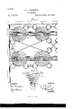
- Figure 1 is a plan view showing a series of my improved bed-springs and the manner in which they are coupled together.
- Fig. 2 is a side elevation of one of the bed-springs, showing the method of attaching it to the bedslat.
- My invention relates to springs for beds; and it consists in the detailed construction and combination of the same, as hereinafter fully described, whereby the spaces between the springs are in a great measure filled up, and the tick or mattress is prevented from falling through between the springs which support it.
- These springs by having a very wide spread bearing against the tick or 1nat tress, are prevented from turning over when the weight upon the mattress does not come directly over the center of the springs.
- the spaces between the outer rows of springs and the frame of the bed, both at the ends and at the sides, are also in a great measure filled up, and the mattress is prevented from falling through at those points.
- A is the bed-spring, formed with a large hook, a, at its lower end.
- the lowest coil of the spring rests upon the surface of the bedslat B, while the hook (it passes beneath it and holds the spring in position. The coils the lowest upward.
- the top coil is provided with three loops, 0 c and 0. After the loop 0 is formed the wire of which the spring is formed is carried oif and forms the loop 0 of the spring, which stands diagonally opposite to it on the next bedslat.
- the loops 0 c and c of the top coils of the springs are to increase the bearingsurface upon which the mattress rests and to fill in the spaces between the springs, and also the spaces between the outer rows of springs and the frame of the bed D, so that the tick or mattress cannot fall through between the springs at those points.
- the wires connecting the loops 0 cross one another and assist in supporting the mattress and in distributing the pressure which comes on any one spring over those springs next adjacent to it.
- hooks for connecting the springs at various points. These hooks have the bent round portions of them made very long, so that they will not readily drop off when the springs are moved, and the hooks are not obliged to be closed round the wire of the springs to make them hold securely.
- These hooks can be applied in various ways, according to the strength of bed required. They may unite the loops 0 of the springs either directly or diagonally, or they may be used to unite the top coils themselves of the springs, the only alteration being in the length of the hook required for the different positions.
- bed-springs have been arranged in pairs connected by a diagonal rod, said rod being a continuation of the upper coils of the springs, and said springs have been formed with hooks fitted to engage the slats; and I do not broadly claim such constructions as my invention.
- a series of bed-springs, A each of which is provided with the hook a and with the loops 0 and c, united together diagonally in pairs by a wire which forms the continuation of the said loops a, substantially as shown and described, and for the purpose set forth.
- a series of bed-springs, A each of which is provided with the hook a and with the loops 0 and c, united together diagonally in pairs by a wire which forms the continuation of the said loops 0', in combination with the hooks continuation of'the said loops 0', hooks E, for E, for further uniting the next adjacent spring further uniting the next adjacent springs in 10 of the series, substantially as described and the series, slats B, and frame D, substantially shown. as described and shown.
Landscapes
- Mattresses And Other Support Structures For Chairs And Beds (AREA)
Description
(No Model.)
, J. P. LEGGETT.
BED SPRING.
No. 318,758. Patented May 26, 1885.
Fig.1.
WITNESSES: 3 IN'VENTOR:
ATTORNEYS.
UNTTnn STATES PATENT Trice.
JOSEPH P. LEGGETT, OF OARROLLTON, MISSOURI.
BED-SPRING.
SPECIFICATION forming part of Letters Patent No. 318,758, dated May 26, 1885.
Application filed February 7, 1885.
' To all whom it may concern.-
Be it known that I, J osErH PALMER LEG- GETT, a citizen of the United States, residing at Oarrollton, in the county of Carroll and State of Missouri, have invented certain new and useful Improvements in Bed-Springs, of which the following is a description.
Figure 1 is a plan view showing a series of my improved bed-springs and the manner in which they are coupled together. Fig. 2 is a side elevation of one of the bed-springs, showing the method of attaching it to the bedslat.
My invention relates to springs for beds; and it consists in the detailed construction and combination of the same, as hereinafter fully described, whereby the spaces between the springs are in a great measure filled up, and the tick or mattress is prevented from falling through between the springs which support it. These springs, by having a very wide spread bearing against the tick or 1nat tress, are prevented from turning over when the weight upon the mattress does not come directly over the center of the springs. The spaces between the outer rows of springs and the frame of the bed, both at the ends and at the sides, are also in a great measure filled up, and the mattress is prevented from falling through at those points. The manner in which the separate springs are coupled together and combined distributes the weight of any person resting on the mattress over the adjacent springs in addition to those directly underneath and keeps the various parts of the mattress at the same level. YVhen several per sons occupy the same bed, they will lie at substantially the same level instead of pressing down the springs immediately underneath them to various heights corresponding with their respective weights.
I will now proceed to describe my invention with reference to the accompanying drawings, in which similar letters of reference indicate corresponding parts.
A is the bed-spring, formed with a large hook, a, at its lower end. The lowest coil of the spring rests upon the surface of the bedslat B, while the hook (it passes beneath it and holds the spring in position. The coils the lowest upward.
(No model.)
varied according to the amount of elasticity required. The top coil is provided with three loops, 0 c and 0. After the loop 0 is formed the wire of which the spring is formed is carried oif and forms the loop 0 of the spring, which stands diagonally opposite to it on the next bedslat. The loops 0 c and c of the top coils of the springs are to increase the bearingsurface upon which the mattress rests and to fill in the spaces between the springs, and also the spaces between the outer rows of springs and the frame of the bed D, so that the tick or mattress cannot fall through between the springs at those points. The wires connecting the loops 0 cross one another and assist in supporting the mattress and in distributing the pressure which comes on any one spring over those springs next adjacent to it.
E are hooks for connecting the springs at various points. These hooks have the bent round portions of them made very long, so that they will not readily drop off when the springs are moved, and the hooks are not obliged to be closed round the wire of the springs to make them hold securely. These hooks can be applied in various ways, according to the strength of bed required. They may unite the loops 0 of the springs either directly or diagonally, or they may be used to unite the top coils themselves of the springs, the only alteration being in the length of the hook required for the different positions.
Heretofore bed-springs have been arranged in pairs connected by a diagonal rod, said rod being a continuation of the upper coils of the springs, and said springs have been formed with hooks fitted to engage the slats; and I do not broadly claim such constructions as my invention.
Having thus described my invention, what I claim as new, and desire to secure by Letters Patent, is-
1. A series of bed-springs, A, each of which is provided with the hook a and with the loops 0 and c, united together diagonally in pairs by a wire which forms the continuation of the said loops a, substantially as shown and described, and for the purpose set forth.
2. A series of bed-springs, A, each of which is provided with the hook a and with the loops 0 and c, united together diagonally in pairs by a wire which forms the continuation of the said loops 0', in combination with the hooks continuation of'the said loops 0', hooks E, for E, for further uniting the next adjacent spring further uniting the next adjacent springs in 10 of the series, substantially as described and the series, slats B, and frame D, substantially shown. as described and shown.
3. The combination of a series of bed-springs, JOSEPH P. LEG GETT. A, each of which is provided with the hook Witnesses: a, and with the loops 0 and c, united together S. B. ELGENT,
diagonally in pairs by a wire which forms the A. J. SNIDER.
Publications (1)
| Publication Number | Publication Date |
|---|---|
| US318758A true US318758A (en) | 1885-05-19 |
Family
ID=2387903
Family Applications (1)
| Application Number | Title | Priority Date | Filing Date |
|---|---|---|---|
| US318758D Expired - Lifetime US318758A (en) | Bed-spring |
Country Status (1)
| Country | Link |
|---|---|
| US (1) | US318758A (en) |
-
0
- US US318758D patent/US318758A/en not_active Expired - Lifetime
Similar Documents
| Publication | Publication Date | Title |
|---|---|---|
| US4555097A (en) | Combination round coil spring and rectangular torsion coil spring assembly | |
| US7237282B2 (en) | Stackable and stable bedding foundation | |
| US318758A (en) | Bed-spring | |
| US2360966A (en) | Bedspring | |
| US1344636A (en) | jackson | |
| US628498A (en) | Bed-bottom. | |
| US564531A (en) | Couch | |
| US120587A (en) | Improvement in bed-bottoms | |
| US181816A (en) | Improvement in spring bed-bottoms | |
| US276421A (en) | Bed-spring | |
| US254277A (en) | Spring-bed | |
| US163760A (en) | Improvement in bottoms for chairs | |
| US277121A (en) | Bed-spring | |
| US160913A (en) | Improvement in bed-bottoms | |
| US271554A (en) | Bed-spring | |
| US143970A (en) | Improvement in bottoms for beds | |
| US187846A (en) | Improvement in spring bed-bottoms | |
| US540194A (en) | James b | |
| US314427A (en) | Chaeles caeleton | |
| US183772A (en) | Improvement in bed-bottoms | |
| US593279A (en) | Spring-mattress | |
| US348539A (en) | Spring bed-bottom | |
| US5588163A (en) | Support deck for mattress or seat | |
| US422030A (en) | Spring-bed | |
| US392529A (en) | Edwin f |