US3180238A - Groove filler - Google Patents
Groove filler Download PDFInfo
- Publication number
- US3180238A US3180238A US125154A US12515461A US3180238A US 3180238 A US3180238 A US 3180238A US 125154 A US125154 A US 125154A US 12515461 A US12515461 A US 12515461A US 3180238 A US3180238 A US 3180238A
- Authority
- US
- United States
- Prior art keywords
- groove
- filler
- pavement
- groove filler
- sides
- Prior art date
- Legal status (The legal status is an assumption and is not a legal conclusion. Google has not performed a legal analysis and makes no representation as to the accuracy of the status listed.)
- Expired - Lifetime
Links
- 239000000945 filler Substances 0.000 title claims description 125
- 239000000463 material Substances 0.000 claims description 24
- 239000003566 sealing material Substances 0.000 claims description 6
- 230000037431 insertion Effects 0.000 claims description 4
- 238000003780 insertion Methods 0.000 claims description 4
- 238000007789 sealing Methods 0.000 description 10
- 238000010276 construction Methods 0.000 description 8
- 238000004873 anchoring Methods 0.000 description 7
- 230000008602 contraction Effects 0.000 description 4
- 238000007373 indentation Methods 0.000 description 3
- 239000000123 paper Substances 0.000 description 3
- 239000003000 extruded plastic Substances 0.000 description 2
- 239000000203 mixture Substances 0.000 description 2
- 230000035515 penetration Effects 0.000 description 2
- 239000004033 plastic Substances 0.000 description 2
- 238000004901 spalling Methods 0.000 description 2
- 241001233242 Lontra Species 0.000 description 1
- 239000011111 cardboard Substances 0.000 description 1
- 238000004140 cleaning Methods 0.000 description 1
- 150000001875 compounds Chemical class 0.000 description 1
- 239000002184 metal Substances 0.000 description 1
- 230000003014 reinforcing effect Effects 0.000 description 1
- 239000004576 sand Substances 0.000 description 1
- 238000000926 separation method Methods 0.000 description 1
- 239000000126 substance Substances 0.000 description 1
Images


Classifications
-
- E—FIXED CONSTRUCTIONS
- E01—CONSTRUCTION OF ROADS, RAILWAYS, OR BRIDGES
- E01C—CONSTRUCTION OF, OR SURFACES FOR, ROADS, SPORTS GROUNDS, OR THE LIKE; MACHINES OR AUXILIARY TOOLS FOR CONSTRUCTION OR REPAIR
- E01C23/00—Auxiliary devices or arrangements for constructing, repairing, reconditioning, or taking-up road or like surfaces
- E01C23/02—Devices for making, treating or filling grooves or like channels in not-yet-hardened paving, e.g. for joints or markings; Removable forms therefor; Devices for introducing inserts or removable insert-supports in not-yet-hardened paving
- E01C23/021—Removable, e.g. reusable, forms for grooves or like channels ; Installing same prior to placing the paving
-
- E—FIXED CONSTRUCTIONS
- E01—CONSTRUCTION OF ROADS, RAILWAYS, OR BRIDGES
- E01C—CONSTRUCTION OF, OR SURFACES FOR, ROADS, SPORTS GROUNDS, OR THE LIKE; MACHINES OR AUXILIARY TOOLS FOR CONSTRUCTION OR REPAIR
- E01C11/00—Details of pavings
- E01C11/02—Arrangement or construction of joints; Methods of making joints; Packing for joints
- E01C11/04—Arrangement or construction of joints; Methods of making joints; Packing for joints for cement concrete paving
- E01C11/10—Packing of plastic or elastic materials, e.g. wood, resin
Definitions
- grooves are formed before the paving material has become fully hardened to divide the pavement into slabs or blocks which can move toward and from each other during the contraction and expansion of the pavement. Also when two lanes of pavement are laid side by side, it is necessary to provide grooves and sealers between the lanes. After these grooves are formed in the pavement while still only partly hardened, it is desirable to provide temporary fillers for the grooves for the purpose of keeping these grooves clear of foreign material which might enter the same if they were left open. After the pavement has become hard, these temporary groove fillers are removed and the grooves are then filled with a sealing means to form a permanent closure of the grooves during the use of the pavement.
- One of the objects of this invention is toprovide a groove filler which can be readily removed from the groove when it is desired to apply a sealing substance to the groove.
- Another object is to provide a temporary groove filler which is so formed that a part of the same can be removed while the lower part remains in the groove to limit the amount of sealing material necessary to fill the groove.
- Another object is to provide a groove filler which is provided with lines of weakness which permit the upper part of the groove filler to be separated from the lower part along the lines of weakness and removed from the groove while the lower part remains in place therein.
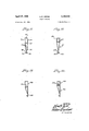
- FIG. 1 is a perspective view of a groove filler embodying this invention.
- FIGS. 26 inclusive are end views of groove fillers of various shapes or modified forms.
- FIG. 7 is a fragmentary, transverse, sectional elevation of a pavement joint showing a groove as originally formed between two pavement slabs.
- FIG. 8 is a similar view showing a tapered groove filler such as illustrated in FIG. 1 within the groove.
- FIG. 9 is a sectional view similar to FIG. 8 but showing the upper part of the groove filler removed from the groove.
- FIG. 10 is a similar view showing-a sealer positioned in the upper portion of the groove.
- FIGS. 11-14 inclusive are end views of groove fillers of various forms which are made of extruded plastic material.
- 15 and 16 represent two adjacent pavement slabs or' parts and 17 is a center plate positioned between the two slabs to form a plane of weakness between the slabs so in case of contraction the slabs will separate from each other approximately along the plane of the center plate rather than to break away from each other at various angles.
- a groove 19 is provided between the two slabs.
- This groove may be formed in any suitable or desired manner. It may be cut in the pavement before the same hardens completely, or it may be formed by means of a bar, not shown, which is embedded in the wet concrete and pulled outwardly out of the. same when the concrete has become partly hard.
- a guide finger 20 may be used which is in the form of a metal plate formed to fit at its lower edge over the center' plate 17 and having a groove 21 extending downwardly from the upper end thereof and into which a groove-forming bar (not shown) may fit, the finger 20 ensuring that the groove will be directly above the center plate.
- This invention relates particularly to the temporary groove fillers which serve to close the groove while the pavement is hardening to exclude foreign material therefrom until any of the usual sealing means are placed in the groove.
- These groove fillers are at least partly removable. from the groove to provide room for the insertion of a sealer into the groove.
- the lower part of the groove filler is preferably left in the groove so as to reduce the amount of sealing material required in the groove.
- My improved groove filler may be made of a plastic material or paper stock or card board suitably coated with wax or other relatively waterproof material so that the groove filler will not become deterioriated when wet.
- the groove filler is preferably of a length equal to the width of the pavement strip, or longer if placed in a groove between pavement lanes.
- the groove filler as shown in FIGS. l-6 comprises a single strip of Wax paper which is bent to form a top surface 25 and two sides 26, the sides converging downwardly toward the lower edge thereof, and the two sides 26 adjacent to the lower portion of the filler may be secured together in any desired manner, for example, by means of fasteners 28, or in any other manner so as to form downwardly extending lower edges.
- the lower edges 29 of the sides 26 of the groove filler are preferably detached from each other so that they can become flared out and so that they extend in upwardly inclined directions when located in the lower part of the groove for the purpose of anchoring or holding the groove filler in the groove.
- the Webs 29 may fold upwardly against the Since it is desired to remove the upper portion of the groove filler prior to placing a sealer or sealing compound into the groove, the two sides 26 of the groove filler are provided with lines of weakness which, for example, may be indentations or perforations extending lengthwise thereof, as indicated at 30, and along which the upper portion of the groove filler may be readily torn or detached from the lower portion thereof.
- a secondary filler member or part 35 which may be shaped somewhat like the main groove filler but of somewhat less vertical dimension.
- This secondary filler is located between the sides 26 of the main groove filler and includes a'top wall 36 and sides 37 converging downwardly between the sides 26 and held in place between the main groove filler by the same staples or fastening devices 28 which also hold the sides 26 together.
- the inner groove filler 30 terminates at its lower edge at the portions of the sides 26 having the outwardly extending webs 29.
- the upper wall 36 of the inner groove filler part preferably terminates at or sneaess 53 slightly below the lines of weakness 3t) so that the upper portion of the outer or main part of the groove filler can be readily torn along the lines of weakness without disturbing the inner groove filler part.
- the upper wall 36 also constitutes a cross brace between the side walls of the groove filler.
- the groove filler shown in FIG. 1 is particularly well adapted for use in connection with grooves which taper downwardly. If desired, however, for use in connection with grooves having parallel sides, the groove filler may be formed as shown in FIG. 2, in which the sides 40 of the groove filler extend parallel to each other for a substantial distance before converging inwardly toward each other, as shown at 41.
- the inner groove filler portion 42 in this case is shorter than the part shown in FIG. 1.
- FIG. 3 I have shown still another form of groove filler in which the upper portion 45 of the groove filler has parallel sides which extend only a short distance from the upper edge thereof and the inner groove filler portion 46 extends farther upwardly to the lower part of the upper portion 45 of the main groove filler. It is of course to be understood that the depth to which the upper groove filler portion extends into the groove depends largely upon the nature of the sealing material to be used in the groove.
- FIG. 4 I have shown still another form of groove filler in which no inner filler member is employed.
- This groove filler has an upper portion 50 with lines of weakness 51 and with the sides being brought together and extending downwardly to their lower ends.
- FIG. 5 a somewhat similar construction is illustrated in which the upper part 54 of the groove filler is of triangular cross section and also terminates in parallel sides in contact with each other and without an inner groove filler portion.
- FIG. 6 I have shown another type of groove filler which is intended for use in cases in which a pavement lane is laid along a side of another lane which has already hardened.
- the groove filler shown in FIG. 6 is intended primarily for use between the two lanes of pavement and this groove filler has an upper part formed to provide a top surface 60 from which the sides 61 extend downwardly and come together a short distance below the top surface 69.
- 62 represents lines of weakness along which the upper portion of the groove filler may be torn or separated from the lower portion thereof.
- 63 and 64 represent the sides of the groove filler which extend downwardly in contact with each other and in which a side 64 is intended to lie in contact with the vertical edge of a pavement lane which has already become hardened.
- the other side 63 is provided with a lower part 65 which may be bent into an upwardly extending angle by contact with the pavement so as to anchor the groove filler in the fresh pavement.
- FIGS. 11-14 I have illustrated groove fillers which can be readily made of an extruded plastic material.
- a groovefiller is shown which has the upper portion thereof formed to fill a groove with approximately parallel sides.
- the groove filler shown in FIG. 11 has straight sides 70 and 71 which converge slightly toward the lower portion thereof.
- a top wall '72 is provided, and intermediate of the two side walls a transverse frame or reinforcing member 73 is employed to brace the side walls against collapsing toward each other.
- the lower ends of the side walls terminate in a lower portion 74, the sides of which converge into a single, downwardly extending fin 75, the lower end of which terminates in outwardly extending anchoring webs 76 which correspond to the webs 29 shown in FIGS. 1-5, and also serve the purpose of retaining the lower portion of the groove filler in the groove.
- the upper and lower portions of this groove filler are connected at the lower ends of the side walls 70 and 71 by means of channels or indentations of less thickness than the walls, which form lines of weakness which enable the upper portion of the groove filler to be readily torn from the lower portion 74 when it is desired to fill the groove with sealing means.
- the upper portion 80 of the sealing member is of much less height than the one shown in FIG. 11, and the lower portion 81 is longer, the two sides of the lower portion terminating in a fin 82 having the upwardly extending anchoring webs 83 formed on the lower edge of the fin.
- the upper and lower portions of this groove filler are connected by channels or indentations 84 which constitute lines of weakness along which the upper portion 80 may be torn from the lower portion 81.
- the difference between the constructions shown in FIGS. 11 and 12 is mainly because of the type of sealing means to be employed to fill the part of the groove which has been occupied by the upper portions of the groove filler.
- the construction shown in FIG. 11 is best adapted for use with seals made of an extruded rubber-like material, and the structure of FIG. 12 is better for use with a poured seal.
- FIGS. 13 and 14 show groove fillers for use in connection wit-hgrooves in pavements of which one strip has been hardened and another strip is poured next to the hardened strip.
- the groove filler shown in FIG. 13 has a straight wall 88 to be arranged against the edge of the hardened pavement strip and extending downwardly to the fin 89 and forming parts of both the upper and lower portions of the groove filler.
- These upper and lower portions are connected by means of channels forming lines of weakness 90 separating the upper and lower portions of the groove filler from each other, and these channels 90 of less thickness may be formed in the extruding of the groove filler.
- FIG. 14 shows a groove filler in which the upper portion 93 is much shorter in height than the lower portion 94, thus leaving in the pavement groove after the upper portion has been removed, a rather shallow recess into which a sealing composition of the usual type may be poured.
- the groove filler shown in FIG. 14 has channels 95 of its walls formed of material less thickness to form lines of weakness along which the upper portion of the groove filler may be torn from the lower portion thereof.
- the anchoring fins in any of the groove fillers described otter very little resistance to the insertion of the groove filler into the grooves since they extend outwardly and upwardly from the fins but will of course hold the lower portions of the groove fillers securely in the grooves, particularly after the concrete has hardened.
- the groove fillers in all of the constructions shown have the upper portions formed in accordance with the sealing means which are intended to be employed for filling the grooves after the pavement has hardened.
- the top wall of the groove filler as indicated at '72 in FIG. 11 is concave so that the two upper edges extend upwardly beyond the middle portion of this topwall.
- This structure has the advantage that the two upper edges of the top wall extend toward or to the upper surface of the pavement and thus form lines of weakness in the pavement lengthwise of the groove fillers. As a result there will be less concrete above the upwardly extending edge port-ions of the top walls of these groove fillers, so that when these fillers are pulled upwardly out of the grooves, the break in the pavement will be directly upwardly from the edges of the top wall, thus avoiding spalling or breaking of concrete outwardly from the sides of the Walls of the groove.
- This concave structure of the top wall of the groove filler has been found very elfective in preventing spalling of the concrete at the sides of the groove so that repairing of the pavement by filling in the depressions in the top surface of the road bed formed by the spalled portions is not necessary or greatly reduced.
- FIG. 8 I have shown a groove filler such as illustrated in FIG. 1, applied to a groove between the two slabs and .16. It will be noted that the upper face 25 of the groove filler will be approximately flush with the upper surface of the two slabs of the highway. Where my improved filler extends into the slot 19 of the finger 20, the lower ends 29 will, of course, be bent vertically upwardly as shown, but beyond the finger 2t) these lower ends 29 will be flared outwardly approximately as shown in FIG. 1, into engagement with the concrete slabs.
- FIG. 9 I have shown the groove filler after the upper portion of the same has been torn or otherwise removed from the groove, thus leaving the upper part of the groove open 'while the lower portion thereof is closed by means of the inner and lower groove filler portion 35.
- the outwardly extending, lower ends or flanges 29 anchor the groove filler in the concrete slabs 15 and 16 so as to securely hold the lower part of the groove filler in the groove.
- the upper portion of the groove is left open to receive suitable sealing means 100, which may be in the form of a bituminous material poured into the upper part of the groove, or a sealer member of rubber or rubber-like material such, for example, as disclosed in my copending application Serial No. 107,842.
- suitable sealing means 100 which may be in the form of a bituminous material poured into the upper part of the groove, or a sealer member of rubber or rubber-like material such, for example, as disclosed in my copending application Serial No. 107,842.
- a secondary seal is formed so that-in case of a contraction of the pavement slabs suflicient to form openings at the sides of the sealer, the groove filler will to a large extent prevent penetration of foreign material into the groove.
- This penetration of foreign material into a pavement groove is very objectionable since if a suificient quantity of such foreign material enters the groove, then during expansion of the pavement slabs the foreign material in the grooves becomes compacted into a substantially rigid condition resulting in the breaking of the pavement adjacent the groove.
- My improved groove filler saves the expense of cleaning out the grooves before applying the sealing material thereto.
- the lines of weakness are such that when the two portions are pressed downwardly into a groove, separation of the two portions at the lines of weakness will not occur.
- a groove filler of a flexible material and tubular form comprising upper and lower portions integrally connected with each other and separable by weakness lines which are readily tearable, the lower edge of said lower portion terminating in a downwardly extending fin, said fin having at the lower part thereof outwardly and upwardly extending anchoring webs flexibly connected therewith which fold upwardly against said fin when said groove filler is lowered into position in a pavement groove and which engage the pavement at the sides of the groove 7 to resist pulling said lower portion of said groove filler out of said groove when the upper portion is torn upwardly from said lower portion out of said groove.
- a groove filler for positioning between adjacent slabs of a pavement
- said filler being tubular and formed of flexible material and having side walls which terminate at an upper edge, said filler comprising upper and lower portions integrally connected with each other by Weakness lines which are readily tearable,
- a concave top wall having its edges connected with the upper edges of the side walls and forming therewith ridges extending upwardly above the middle portion of said top wall at the sides of said groove filler whereby weakness lines will occur in the pavement immediately above the ridges and will extend vertically therefrom as the concrete sets.
- a groove filler for positioning between adjacent slabs of a pavement
- said filler being tubular and formed of flexible material and comprising upper and lower portions integrally connected with each other by weakness lines which are readily tearable,
- the upper portion of the groove filler having substantially vertical side walls
- top wall having side edges extending above the middle portion thereof
- a filler for insertion into a groove formed in a pavement and having downwardly converging sides comprising a hollow body formed of flexible material and having upper and lower portions formed integral with each other, the upper portion being of sufficient width to close the upper portion of the groove, said portions being connected with each other by weakness lines extending parallel to the upper surface of the pavement and below the same and along which the upper portion is separable from the lower portion by tearing along said weakness lines to leave the upper part of the groove open to receive a sealing material.
Landscapes
- Engineering & Computer Science (AREA)
- Architecture (AREA)
- Civil Engineering (AREA)
- Structural Engineering (AREA)
- Road Paving Structures (AREA)
Description
April 27, 1965 A. F. CRONE 3,180,238
GROOVE FILLER Filed July 19, 1961 3 Sheets-Sheet 1 L INVENTOR 65 BY %W ATTORNEYS.
April 27, 1965 A. F. CRONE 3,180,238
GROOVE FILLER Filed July 19, 1961 3 Sheets-Sheet 2 M WMW ATTORNEYS.
A. F CRQNE GROOVE FILLER April 27, 1965 Filed July 19 1961 ATTORNEYS.
United States Patent 3,180,238 GROOVE FILLER Alfred F. Crone, Williamsville, N.Y., assignor to Acme Highway Products Corporation, Buffalo, N.Y. Filed July 19, 1961, Ser. No. 125,154 7 Claims. (Cl. 94-18) This invention relates to improvements in fillers which are removably positioned in grooves at pavement joints to close these grooves from the time that they are formed until permanent sealers are placed into the grooves.
In the laying of pavements, grooves are formed before the paving material has become fully hardened to divide the pavement into slabs or blocks which can move toward and from each other during the contraction and expansion of the pavement. Also when two lanes of pavement are laid side by side, it is necessary to provide grooves and sealers between the lanes. After these grooves are formed in the pavement while still only partly hardened, it is desirable to provide temporary fillers for the grooves for the purpose of keeping these grooves clear of foreign material which might enter the same if they were left open. After the pavement has become hard, these temporary groove fillers are removed and the grooves are then filled with a sealing means to form a permanent closure of the grooves during the use of the pavement.
One of the objects of this invention is toprovide a groove filler which can be readily removed from the groove when it is desired to apply a sealing substance to the groove.
Another object is to provide a temporary groove filler which is so formed that a part of the same can be removed while the lower part remains in the groove to limit the amount of sealing material necessary to fill the groove.
Another object is to provide a groove filler which is provided with lines of weakness which permit the upper part of the groove filler to be separated from the lower part along the lines of weakness and removed from the groove while the lower part remains in place therein.
It is also an object to provide a groove filler having upper and lower portions detachably connected and in which the lower portion is provided with anchoring members which retain the lower portion in the groove while the upper portion is removed therefrom.
In the accompanying drawings:
FIG. 1 is a perspective view of a groove filler embodying this invention.
FIGS. 26 inclusive are end views of groove fillers of various shapes or modified forms.
FIG. 7 is a fragmentary, transverse, sectional elevation of a pavement joint showing a groove as originally formed between two pavement slabs.
FIG. 8 is a similar view showing a tapered groove filler such as illustrated in FIG. 1 within the groove.
FIG. 9 is a sectional view similar to FIG. 8 but showing the upper part of the groove filler removed from the groove.
FIG. 10 is a similar view showing-a sealer positioned in the upper portion of the groove.
FIGS. 11-14 inclusive are end views of groove fillers of various forms which are made of extruded plastic material.
Referring first to FIGS. 7 and 8 to illustrate the use of my improved groove fillers, 15 and 16 represent two adjacent pavement slabs or' parts and 17 is a center plate positioned between the two slabs to form a plane of weakness between the slabs so in case of contraction the slabs will separate from each other approximately along the plane of the center plate rather than to break away from each other at various angles. To further increase this plane of weakness, a groove 19 is provided between the two slabs. This groove may be formed in any suitable or desired manner. It may be cut in the pavement before the same hardens completely, or it may be formed by means of a bar, not shown, which is embedded in the wet concrete and pulled outwardly out of the. same when the concrete has become partly hard. In case a bar of this type is employed, a guide finger 20 may be used which is in the form of a metal plate formed to fit at its lower edge over the center' plate 17 and having a groove 21 extending downwardly from the upper end thereof and into which a groove-forming bar (not shown) may fit, the finger 20 ensuring that the groove will be directly above the center plate.
As soon as possible after the groove 19 has been formed in the pavement, it is desirable to temporarily close this groove to prevent foreign material, such as sand, gravel or the like from entering the groove.
This invention relates particularly to the temporary groove fillers which serve to close the groove while the pavement is hardening to exclude foreign material therefrom until any of the usual sealing means are placed in the groove. These groove fillers are at least partly removable. from the groove to provide room for the insertion of a sealer into the groove. The lower part of the groove filler is preferably left in the groove so as to reduce the amount of sealing material required in the groove.
My improved groove filler may be made of a plastic material or paper stock or card board suitably coated with wax or other relatively waterproof material so that the groove filler will not become deterioriated when wet. The groove filler is preferably of a length equal to the width of the pavement strip, or longer if placed in a groove between pavement lanes. The groove filler as shown in FIGS. l-6, comprises a single strip of Wax paper which is bent to form a top surface 25 and two sides 26, the sides converging downwardly toward the lower edge thereof, and the two sides 26 adjacent to the lower portion of the filler may be secured together in any desired manner, for example, by means of fasteners 28, or in any other manner so as to form downwardly extending lower edges. The lower edges 29 of the sides 26 of the groove filler are preferably detached from each other so that they can become flared out and so that they extend in upwardly inclined directions when located in the lower part of the groove for the purpose of anchoring or holding the groove filler in the groove. When positioning the groove filler 111 a groove, the Webs 29 may fold upwardly against the Since it is desired to remove the upper portion of the groove filler prior to placing a sealer or sealing compound into the groove, the two sides 26 of the groove filler are provided with lines of weakness which, for example, may be indentations or perforations extending lengthwise thereof, as indicated at 30, and along which the upper portion of the groove filler may be readily torn or detached from the lower portion thereof.
It maybe preferable at times, in the construction shown in FIGS. l-6, to provide within the two sides 26 of the groove filler and below the top thereof, a secondary filler member or part 35 which may be shaped somewhat like the main groove filler but of somewhat less vertical dimension. This secondary filler is located between the sides 26 of the main groove filler and includes a'top wall 36 and sides 37 converging downwardly between the sides 26 and held in place between the main groove filler by the same staples or fastening devices 28 which also hold the sides 26 together. The inner groove filler 30 terminates at its lower edge at the portions of the sides 26 having the outwardly extending webs 29. The upper wall 36 of the inner groove filler part preferably terminates at or sneaess 53 slightly below the lines of weakness 3t) so that the upper portion of the outer or main part of the groove filler can be readily torn along the lines of weakness without disturbing the inner groove filler part. The upper wall 36 also constitutes a cross brace between the side walls of the groove filler.
The groove filler shown in FIG. 1 is particularly well adapted for use in connection with grooves which taper downwardly. If desired, however, for use in connection with grooves having parallel sides, the groove filler may be formed as shown in FIG. 2, in which the sides 40 of the groove filler extend parallel to each other for a substantial distance before converging inwardly toward each other, as shown at 41. The inner groove filler portion 42 in this case is shorter than the part shown in FIG. 1.
In FIG. 3 I have shown still another form of groove filler in which the upper portion 45 of the groove filler has parallel sides which extend only a short distance from the upper edge thereof and the inner groove filler portion 46 extends farther upwardly to the lower part of the upper portion 45 of the main groove filler. It is of course to be understood that the depth to which the upper groove filler portion extends into the groove depends largely upon the nature of the sealing material to be used in the groove.
In FIG. 4 I have shown still another form of groove filler in which no inner filler member is employed. This groove filler has an upper portion 50 with lines of weakness 51 and with the sides being brought together and extending downwardly to their lower ends. In FIG. 5 a somewhat similar construction is illustrated in which the upper part 54 of the groove filler is of triangular cross section and also terminates in parallel sides in contact with each other and without an inner groove filler portion. These various forms of groove filler may be used in different instances where their use is best adapted for existing conditions.
In FIG. 6 I have shown another type of groove filler which is intended for use in cases in which a pavement lane is laid along a side of another lane which has already hardened. The groove filler shown in FIG. 6 is intended primarily for use between the two lanes of pavement and this groove filler has an upper part formed to provide a top surface 60 from which the sides 61 extend downwardly and come together a short distance below the top surface 69. In this construction, 62 represents lines of weakness along which the upper portion of the groove filler may be torn or separated from the lower portion thereof. 63 and 64 represent the sides of the groove filler which extend downwardly in contact with each other and in which a side 64 is intended to lie in contact with the vertical edge of a pavement lane which has already become hardened. The other side 63 is provided with a lower part 65 which may be bent into an upwardly extending angle by contact with the pavement so as to anchor the groove filler in the fresh pavement.
In FIGS. 11-14, I have illustrated groove fillers which can be readily made of an extruded plastic material. For example, in FIG. 11 a groovefiller is shown which has the upper portion thereof formed to fill a groove with approximately parallel sides. For this purpose the groove filler shown in FIG. 11 has straight sides 70 and 71 which converge slightly toward the lower portion thereof. In this groove filler a top wall '72 is provided, and intermediate of the two side walls a transverse frame or reinforcing member 73 is employed to brace the side walls against collapsing toward each other. The lower ends of the side walls terminate in a lower portion 74, the sides of which converge into a single, downwardly extending fin 75, the lower end of which terminates in outwardly extending anchoring webs 76 which correspond to the webs 29 shown in FIGS. 1-5, and also serve the purpose of retaining the lower portion of the groove filler in the groove. The upper and lower portions of this groove filler are connected at the lower ends of the side walls 70 and 71 by means of channels or indentations of less thickness than the walls, which form lines of weakness which enable the upper portion of the groove filler to be readily torn from the lower portion 74 when it is desired to fill the groove with sealing means.
In the construction shown in FIG. 12, the upper portion 80 of the sealing member is of much less height than the one shown in FIG. 11, and the lower portion 81 is longer, the two sides of the lower portion terminating in a fin 82 having the upwardly extending anchoring webs 83 formed on the lower edge of the fin. The upper and lower portions of this groove filler are connected by channels or indentations 84 which constitute lines of weakness along which the upper portion 80 may be torn from the lower portion 81. The difference between the constructions shown in FIGS. 11 and 12 is mainly because of the type of sealing means to be employed to fill the part of the groove which has been occupied by the upper portions of the groove filler. For example, the construction shown in FIG. 11 is best adapted for use with seals made of an extruded rubber-like material, and the structure of FIG. 12 is better for use with a poured seal.
FIGS. 13 and 14 show groove fillers for use in connection wit-hgrooves in pavements of which one strip has been hardened and another strip is poured next to the hardened strip. The groove filler shown in FIG. 13 has a straight wall 88 to be arranged against the edge of the hardened pavement strip and extending downwardly to the fin 89 and forming parts of both the upper and lower portions of the groove filler. These upper and lower portions are connected by means of channels forming lines of weakness 90 separating the upper and lower portions of the groove filler from each other, and these channels 90 of less thickness may be formed in the extruding of the groove filler. FIG. 14 shows a groove filler in which the upper portion 93 is much shorter in height than the lower portion 94, thus leaving in the pavement groove after the upper portion has been removed, a rather shallow recess into which a sealing composition of the usual type may be poured. The groove filler shown in FIG. 14 has channels 95 of its walls formed of material less thickness to form lines of weakness along which the upper portion of the groove filler may be torn from the lower portion thereof.
The anchoring fins in any of the groove fillers described otter very little resistance to the insertion of the groove filler into the grooves since they extend outwardly and upwardly from the fins but will of course hold the lower portions of the groove fillers securely in the grooves, particularly after the concrete has hardened.
The groove fillers in all of the constructions shown have the upper portions formed in accordance with the sealing means which are intended to be employed for filling the grooves after the pavement has hardened.
It will be noted on FIGS. 11-14 that the top wall of the groove filler, as indicated at '72 in FIG. 11 is concave so that the two upper edges extend upwardly beyond the middle portion of this topwall. This structure has the advantage that the two upper edges of the top wall extend toward or to the upper surface of the pavement and thus form lines of weakness in the pavement lengthwise of the groove fillers. As a result there will be less concrete above the upwardly extending edge port-ions of the top walls of these groove fillers, so that when these fillers are pulled upwardly out of the grooves, the break in the pavement will be directly upwardly from the edges of the top wall, thus avoiding spalling or breaking of concrete outwardly from the sides of the Walls of the groove. This concave structure of the top wall of the groove filler has been found very elfective in preventing spalling of the concrete at the sides of the groove so that repairing of the pavement by filling in the depressions in the top surface of the road bed formed by the spalled portions is not necessary or greatly reduced.
In FIG. 8 I have shown a groove filler such as illustrated in FIG. 1, applied to a groove between the two slabs and .16. It will be noted that the upper face 25 of the groove filler will be approximately flush with the upper surface of the two slabs of the highway. Where my improved filler extends into the slot 19 of the finger 20, the lower ends 29 will, of course, be bent vertically upwardly as shown, but beyond the finger 2t) these lower ends 29 will be flared outwardly approximately as shown in FIG. 1, into engagement with the concrete slabs.
In FIG. 9 I have shown the groove filler after the upper portion of the same has been torn or otherwise removed from the groove, thus leaving the upper part of the groove open 'while the lower portion thereof is closed by means of the inner and lower groove filler portion 35. During the tearing or removal of the outer and upper part of the groove filler, the outwardly extending, lower ends or flanges 29 anchor the groove filler in the concrete slabs 15 and 16 so as to securely hold the lower part of the groove filler in the groove.
By means of this construction the upper portion of the groove is left open to receive suitable sealing means 100, which may be in the form of a bituminous material poured into the upper part of the groove, or a sealer member of rubber or rubber-like material such, for example, as disclosed in my copending application Serial No. 107,842. By filling the lower part of the groove with the part of the groove filler which is left in the same, a substantial saving in the sealer material is effected. Also by the use of my improved groove filler, during expansion of the pavement slabs and contraction of the groove, the sealer 100 may be pressed partly into the readily flexible groove filler part left in the groove so that a lesser quantity of the sealer is forced upwardly above the level of the slabs 15 and 16. This is due to the fact that my improved groove filler is flexible so that the sealer may be pressed into it.
Furthermore, by forming the groove filler as shown, a secondary seal is formed so that-in case of a contraction of the pavement slabs suflicient to form openings at the sides of the sealer, the groove filler will to a large extent prevent penetration of foreign material into the groove. This penetration of foreign material into a pavement groove is very objectionable since if a suificient quantity of such foreign material enters the groove, then during expansion of the pavement slabs the foreign material in the grooves becomes compacted into a substantially rigid condition resulting in the breaking of the pavement adjacent the groove.
My improved groove filler saves the expense of cleaning out the grooves before applying the sealing material thereto.
While the two portions of the groove filler are connected so as to be readily separated from each other, the lines of weakness are such that when the two portions are pressed downwardly into a groove, separation of the two portions at the lines of weakness will not occur.
It will be understood that various changes in the details, materials and arrangements of parts which have been herein described and illustrated in order to explain the nature of the invention may be made by those skilled in the art within the principle and scope of the invention as expressed in the appended claims.
I claim:
1. A groove filler of a flexible material and tubular form and comprising upper and lower portions integrally connected with each other and separable by weakness lines which are readily tearable, the lower edge of said lower portion terminating in a downwardly extending fin, said fin having at the lower part thereof outwardly and upwardly extending anchoring webs flexibly connected therewith which fold upwardly against said fin when said groove filler is lowered into position in a pavement groove and which engage the pavement at the sides of the groove 7 to resist pulling said lower portion of said groove filler out of said groove when the upper portion is torn upwardly from said lower portion out of said groove.
2. A groove filler for positioning between adjacent slabs of a pavement,
said filler being tubular and formed of flexible material and having side walls which terminate at an upper edge, said filler comprising upper and lower portions integrally connected with each other by Weakness lines which are readily tearable,
a concave top wall having its edges connected with the upper edges of the side walls and forming therewith ridges extending upwardly above the middle portion of said top wall at the sides of said groove filler whereby weakness lines will occur in the pavement immediately above the ridges and will extend vertically therefrom as the concrete sets.
3. A groove filler for positioning between adjacent slabs of a pavement,
said filler being tubular and formed of flexible material and comprising upper and lower portions integrally connected with each other by weakness lines which are readily tearable,
the upper portion of the groove filler having substantially vertical side walls,
a top wall having side edges extending above the middle portion thereof,
the side edges of said top wall being secured to the upper edges of the side walls and forming therewith upwardly extending ridges, whereby weakness lines will occur in the pavement immediately above the ridges and will extend vertically therefrom as the concrete sets.
4. A filler for insertion into a groove formed in a pavement and having downwardly converging sides, said filler comprising a hollow body formed of flexible material and having upper and lower portions formed integral with each other, the upper portion being of sufficient width to close the upper portion of the groove, said portions being connected with each other by weakness lines extending parallel to the upper surface of the pavement and below the same and along which the upper portion is separable from the lower portion by tearing along said weakness lines to leave the upper part of the groove open to receive a sealing material.
5. A groove filler according to claim 4 and including anchoring means on said lower portion of said filler which embed themselves in the material of the pavement at the sides of the groove to resist dislodging of said lower portion while the upper portion is removed therefrom.
6. A groove filler according to claim 4 in which said filler is made of a synthetic plastic composition.
7. A groove filler according to claim 5 in which said filler is made of paper or the like.
References Cited by the Examiner UNITED STATES PATENTS OTHER REFERENCES Roads and Streets, pub., Mar. 1960, page 133 relied on.
JACOB L. NACKENOFF, Primary Examiner.
Dohren 94 -18 X
Claims (1)
- 4. A FILLER FOR INSERTION INTO A GROOVE FORMED IN A PAVEMENT AND HAVING DOWNWARDLY CONVERGING SIDES, SAID FILLER COMPRISING A HOLLOW BODY FORMED OF FLEXIBLE MATERIAL AND HAVING UPPER AND LOWER PORTIONS FORMED INTEGRAL WITH EACH OTHER, THE UPPER PORTION BEING OF SUFFICIENT WIDTH TO CLOSE THE UPPER PORTION OF THE GROOVE, SAID PORTIONS BEING CONNECTED WITH EACH OTHER BY WEAKNESS LINES EXTENDING PARALLEL TO THE UPPER SURFACE OF THE PAVEMENT AND BELOW THE SAME AND ALOG WHICH THE UPPER PORTION IS SEPARABLE FROM THE LOWER PORTION BY TEARING ALONG SAID WEAKNESS LINES TO LEAVE THE UPPER PART OF THE GROOVE OPEN TO RECEIVE A SEALING MATERIAL.
Priority Applications (1)
| Application Number | Priority Date | Filing Date | Title |
|---|---|---|---|
| US125154A US3180238A (en) | 1961-07-19 | 1961-07-19 | Groove filler |
Applications Claiming Priority (1)
| Application Number | Priority Date | Filing Date | Title |
|---|---|---|---|
| US125154A US3180238A (en) | 1961-07-19 | 1961-07-19 | Groove filler |
Publications (1)
| Publication Number | Publication Date |
|---|---|
| US3180238A true US3180238A (en) | 1965-04-27 |
Family
ID=22418431
Family Applications (1)
| Application Number | Title | Priority Date | Filing Date |
|---|---|---|---|
| US125154A Expired - Lifetime US3180238A (en) | 1961-07-19 | 1961-07-19 | Groove filler |
Country Status (1)
| Country | Link |
|---|---|
| US (1) | US3180238A (en) |
Cited By (18)
| Publication number | Priority date | Publication date | Assignee | Title |
|---|---|---|---|---|
| US3234860A (en) * | 1962-06-04 | 1966-02-15 | Clardon Invest Co | Weakened concrete joint and method of forming same |
| US3255680A (en) * | 1962-10-22 | 1966-06-14 | Joint Controls Inc | Means for and method of forming an expansion joint |
| US3276335A (en) * | 1964-01-08 | 1966-10-04 | William F Middlestadt | Joint forming structure |
| US3323426A (en) * | 1964-05-28 | 1967-06-06 | Clipper Mfg Company Inc | Concrete joint insert unit |
| US3330187A (en) * | 1964-12-14 | 1967-07-11 | Western Textile Products Compa | Plastic articles and methods of making same |
| US3413900A (en) * | 1966-09-30 | 1968-12-03 | Acme Highway Prod | Groove filler |
| US3426658A (en) * | 1967-01-26 | 1969-02-11 | Albert J Frederickson | Contraction joint for pavements |
| US3782846A (en) * | 1972-02-28 | 1974-01-01 | R Johnson | Joint forming and sealing device |
| US3967911A (en) * | 1973-11-28 | 1976-07-06 | John Aubrey Miers | Sealing member |
| US4008974A (en) * | 1973-11-28 | 1977-02-22 | L. J. A. Miers (Exports) Limited | Sealing member |
| US4198176A (en) * | 1978-09-22 | 1980-04-15 | Delta National, Inc. | Concrete expansion joint forming structure |
| US4548009A (en) * | 1981-08-19 | 1985-10-22 | Quaker Plastic Corporation | Concrete expansion joint |
| US4934863A (en) * | 1989-02-08 | 1990-06-19 | Brantner Jr William F | Masonry tool |
| US5438804A (en) * | 1989-09-09 | 1995-08-08 | Avon Plastics, Inc. | Landscape edging |
| US6272806B1 (en) * | 1999-03-24 | 2001-08-14 | Face, Iii S. Allen | Joint insert and method/system for using same |
| US20080115440A1 (en) * | 2006-11-22 | 2008-05-22 | Mike Fortney | Replacement expansion joint for cement |
| DE202011104323U1 (en) * | 2011-08-12 | 2012-04-30 | OBS Objekt-Begrünungs-Systeme GmbH | Profile, in particular for Bedetabgrenzung and / or pond / Schwimmteicheinfassung |
| US20150240489A1 (en) * | 2014-02-22 | 2015-08-27 | Ductilcrete Slab Systems, Llc | Concrete floor system using integrated concrete slab and joint filling strips |
Citations (8)
| Publication number | Priority date | Publication date | Assignee | Title |
|---|---|---|---|---|
| US1456373A (en) * | 1920-03-19 | 1923-05-22 | Manell Building Block & Tile C | Building block and construction |
| US1581399A (en) * | 1925-10-19 | 1926-04-20 | Albert C Fischer | Expansion-joint-installing device |
| US1763369A (en) * | 1929-06-20 | 1930-06-10 | Robert R Robertson | Contraction-center-strip mold cap |
| US1951955A (en) * | 1934-03-20 | Air filter | ||
| US2554522A (en) * | 1946-10-01 | 1951-05-29 | John E Carter | Process for making vertical joint sealing strips |
| US3038395A (en) * | 1958-06-09 | 1962-06-12 | William F Middlestadt | Concrete joint |
| US3045891A (en) * | 1959-09-11 | 1962-07-24 | A Aba Cellophane Products Corp | Continuous envelopes |
| US3136022A (en) * | 1960-12-12 | 1964-06-09 | Rotuba Extruders Inc | Joint forming device |
-
1961
- 1961-07-19 US US125154A patent/US3180238A/en not_active Expired - Lifetime
Patent Citations (8)
| Publication number | Priority date | Publication date | Assignee | Title |
|---|---|---|---|---|
| US1951955A (en) * | 1934-03-20 | Air filter | ||
| US1456373A (en) * | 1920-03-19 | 1923-05-22 | Manell Building Block & Tile C | Building block and construction |
| US1581399A (en) * | 1925-10-19 | 1926-04-20 | Albert C Fischer | Expansion-joint-installing device |
| US1763369A (en) * | 1929-06-20 | 1930-06-10 | Robert R Robertson | Contraction-center-strip mold cap |
| US2554522A (en) * | 1946-10-01 | 1951-05-29 | John E Carter | Process for making vertical joint sealing strips |
| US3038395A (en) * | 1958-06-09 | 1962-06-12 | William F Middlestadt | Concrete joint |
| US3045891A (en) * | 1959-09-11 | 1962-07-24 | A Aba Cellophane Products Corp | Continuous envelopes |
| US3136022A (en) * | 1960-12-12 | 1964-06-09 | Rotuba Extruders Inc | Joint forming device |
Cited By (21)
| Publication number | Priority date | Publication date | Assignee | Title |
|---|---|---|---|---|
| US3234860A (en) * | 1962-06-04 | 1966-02-15 | Clardon Invest Co | Weakened concrete joint and method of forming same |
| US3255680A (en) * | 1962-10-22 | 1966-06-14 | Joint Controls Inc | Means for and method of forming an expansion joint |
| US3276335A (en) * | 1964-01-08 | 1966-10-04 | William F Middlestadt | Joint forming structure |
| US3323426A (en) * | 1964-05-28 | 1967-06-06 | Clipper Mfg Company Inc | Concrete joint insert unit |
| US3330187A (en) * | 1964-12-14 | 1967-07-11 | Western Textile Products Compa | Plastic articles and methods of making same |
| US3413900A (en) * | 1966-09-30 | 1968-12-03 | Acme Highway Prod | Groove filler |
| US3426658A (en) * | 1967-01-26 | 1969-02-11 | Albert J Frederickson | Contraction joint for pavements |
| US3782846A (en) * | 1972-02-28 | 1974-01-01 | R Johnson | Joint forming and sealing device |
| US3967911A (en) * | 1973-11-28 | 1976-07-06 | John Aubrey Miers | Sealing member |
| US4008974A (en) * | 1973-11-28 | 1977-02-22 | L. J. A. Miers (Exports) Limited | Sealing member |
| US4198176A (en) * | 1978-09-22 | 1980-04-15 | Delta National, Inc. | Concrete expansion joint forming structure |
| US4548009A (en) * | 1981-08-19 | 1985-10-22 | Quaker Plastic Corporation | Concrete expansion joint |
| US4934863A (en) * | 1989-02-08 | 1990-06-19 | Brantner Jr William F | Masonry tool |
| US5438804A (en) * | 1989-09-09 | 1995-08-08 | Avon Plastics, Inc. | Landscape edging |
| US6272806B1 (en) * | 1999-03-24 | 2001-08-14 | Face, Iii S. Allen | Joint insert and method/system for using same |
| US20080115440A1 (en) * | 2006-11-22 | 2008-05-22 | Mike Fortney | Replacement expansion joint for cement |
| US8955287B2 (en) * | 2006-11-22 | 2015-02-17 | Mike Fortney | Replacement expansion joint for cement |
| DE202011104323U1 (en) * | 2011-08-12 | 2012-04-30 | OBS Objekt-Begrünungs-Systeme GmbH | Profile, in particular for Bedetabgrenzung and / or pond / Schwimmteicheinfassung |
| US20150240489A1 (en) * | 2014-02-22 | 2015-08-27 | Ductilcrete Slab Systems, Llc | Concrete floor system using integrated concrete slab and joint filling strips |
| US20150240503A1 (en) * | 2014-02-22 | 2015-08-27 | Ductilcrete Slab Systems, Llc | Joint filling strip |
| US9359761B2 (en) * | 2014-02-22 | 2016-06-07 | Ductilcrete Slab Systems, Llc | Joint filling strip |
Similar Documents
| Publication | Publication Date | Title |
|---|---|---|
| US3023681A (en) | Combined weakened plane joint former and waterstop | |
| US3956557A (en) | Waterstops | |
| US3179026A (en) | Sealing element for pavement grooves | |
| US3334558A (en) | Concrete joint form | |
| US4090800A (en) | Joint-forming device | |
| US3977802A (en) | Expansion joint and seal | |
| US1586326A (en) | Metallic expansion joint for concrete roads and the like | |
| US3255680A (en) | Means for and method of forming an expansion joint | |
| US3583120A (en) | Control joint filler | |
| US3589664A (en) | Reusable structure for forming joints in concrete | |
| US2093697A (en) | Expansion joint | |
| US4516876A (en) | Precast concrete expansion joint for roads and the like | |
| US3297294A (en) | Collapsible joint forming structure | |
| US2651243A (en) | Joint bar device | |
| US1806275A (en) | Insert for concrete roads and the like | |
| US1697563A (en) | Concrete surfacing joint and means for and method of forming the same | |
| US3038395A (en) | Concrete joint | |
| US3881834A (en) | Joint seals | |
| US1956809A (en) | Load transmission joint for roads | |
| US3413900A (en) | Groove filler | |
| US1916631A (en) | Paving tile | |
| US2042408A (en) | Expansion joint | |
| US1780588A (en) | Concrete road construction | |
| US3234860A (en) | Weakened concrete joint and method of forming same | |
| US2062654A (en) | Parting strip for roadways or the like |