US3167883A - Oven construction - Google Patents
Oven construction Download PDFInfo
- Publication number
- US3167883A US3167883A US208711A US20871162A US3167883A US 3167883 A US3167883 A US 3167883A US 208711 A US208711 A US 208711A US 20871162 A US20871162 A US 20871162A US 3167883 A US3167883 A US 3167883A
- Authority
- US
- United States
- Prior art keywords
- buckstays
- coke oven
- temporary
- construction
- coke
- Prior art date
- Legal status (The legal status is an assumption and is not a legal conclusion. Google has not performed a legal analysis and makes no representation as to the accuracy of the status listed.)
- Expired - Lifetime
Links
- 238000010276 construction Methods 0.000 title claims description 22
- 230000001681 protective effect Effects 0.000 claims description 23
- 238000000034 method Methods 0.000 claims description 10
- 239000000571 coke Substances 0.000 description 45
- 238000010438 heat treatment Methods 0.000 description 13
- 239000007789 gas Substances 0.000 description 7
- XEEYBQQBJWHFJM-UHFFFAOYSA-N Iron Chemical compound [Fe] XEEYBQQBJWHFJM-UHFFFAOYSA-N 0.000 description 6
- 238000004939 coking Methods 0.000 description 4
- 239000004567 concrete Substances 0.000 description 4
- 239000011449 brick Substances 0.000 description 3
- 229910052742 iron Inorganic materials 0.000 description 3
- 239000004566 building material Substances 0.000 description 2
- 239000006227 byproduct Substances 0.000 description 2
- 238000002485 combustion reaction Methods 0.000 description 2
- 239000000463 material Substances 0.000 description 2
- 239000002918 waste heat Substances 0.000 description 2
- 239000002023 wood Substances 0.000 description 2
- 239000004568 cement Substances 0.000 description 1
- 150000001875 compounds Chemical class 0.000 description 1
- 239000004035 construction material Substances 0.000 description 1
- 238000009434 installation Methods 0.000 description 1
- 239000004570 mortar (masonry) Substances 0.000 description 1
- 230000001172 regenerating effect Effects 0.000 description 1
Images

Classifications
-
- C—CHEMISTRY; METALLURGY
- C10—PETROLEUM, GAS OR COKE INDUSTRIES; TECHNICAL GASES CONTAINING CARBON MONOXIDE; FUELS; LUBRICANTS; PEAT
- C10B—DESTRUCTIVE DISTILLATION OF CARBONACEOUS MATERIALS FOR PRODUCTION OF GAS, COKE, TAR, OR SIMILAR MATERIALS
- C10B29/00—Other details of coke ovens
-
- Y—GENERAL TAGGING OF NEW TECHNOLOGICAL DEVELOPMENTS; GENERAL TAGGING OF CROSS-SECTIONAL TECHNOLOGIES SPANNING OVER SEVERAL SECTIONS OF THE IPC; TECHNICAL SUBJECTS COVERED BY FORMER USPC CROSS-REFERENCE ART COLLECTIONS [XRACs] AND DIGESTS
- Y10—TECHNICAL SUBJECTS COVERED BY FORMER USPC
- Y10T—TECHNICAL SUBJECTS COVERED BY FORMER US CLASSIFICATION
- Y10T29/00—Metal working
- Y10T29/49—Method of mechanical manufacture
- Y10T29/49826—Assembling or joining
Definitions
- FIG. 1 A first figure.
- a by-product coke oven battery comprises horizontally elongated coking chambers extending transversely of the battery and alternating with heating walls, each of which includes a horizontal row of vertical heating fiues.
- Regenerator chambers are disposed beneath the coking chambers and heating walls and extend transversely of the battery. The lower end of the heating lines in each heating wall are connected to the upper edges of associated regenerator chambers, and the lower edge of each regenerator chamber communicates with a sole channel therebeneath.
- Coke oven batteries are made from highly refractory bricks. Such bricks cannot be laid and built up in the open air, for they would then be damaged by rain and frost. Moreover, the mortar used to cement the brickwork is also sensitive to the elements. Accordingly, before commencing the construction of a refractory brick wall for a large oven unit, for instance a coke oven battery, it is customary to erect a protective roof for the coke oven.
- the length of the battery will be approximately ninety to one hundred feet, the width thereof (the length of the coke oven chamber) about forty to fifty feet, and the overall height about twentyfive to thirty feet. Accordingly, the construction of a shelter for such coke oven battery is a considerable undertaking.
- the protective roof is of wooden construction and utilizes Wooden ties and struts for support. The roof is covered with sheeting boards and paper. The same covering is utilized on the side to pro tect the brickwork against rain and the like. In winter, the side walls of the oven may be boarded upon the outside to permit heating.
- Protective roofs for ovens have also been made of iron and covered with roofing sheets.
- Yet another object is to provide a method of constructing temporary scaffolding for a coke oven battery where- 3,.ih7,883 Patented Feio. 2, 1965 by ready access to various heights along the coke oven is provided.
- a further object is to provide a unique temporary structure comprising a protective roofing for a coke oven battery and scaffolding along the side thereof.
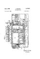
- FIG. 1 is a transverse sectional view, partially through a coking chamber, partially through a heating wall, of a completed coke oven battery;
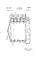
- FIG. 2 is a transverse sectional View of a coke oven battery sub-structure showing a protective roof for the coke oven battery and temporary scaffolding;
- FIG. 3 is an enlarged View of one of the scaffolds shown on the right hand side of FIG. 2;
- FIG. 4 is a horizontal section taken along the line 4-4- of FIG. 3;
- FIG. 5 is a plan view taken along the line 5-5 of FIG. 2.
- FIG. 1 shows the completed coke oven battery generally designated by the reference numeral 10.
- This coke oven battery is of the underjet, rich gas, hairpin type, although the invention is not limited thereto and is equally adaptable to other types of coke ovens, e.g., two-divided, four-divided, crossover, compound, waste heat, etc.
- the battery 10 comprises a supporting deck 12 which is preferably made of concrete and generally forms the roof of a conventional basement space 14.
- the deck 12 is supported by concrete pillars 16 which in turn rest upon foundation plate 18.
- Oven base plate 20 rests upon the deck 12 and provides a support means for the coke oven brickwork which forms an upper section 22 and a lower section 24 which merge into an intermediate horizontal masonry layer 26.
- the upper section 22 of the battery comprises horizontally elongated coking chambers 28 alternating with heating walls 3t). Extending between each two adjacent heating walls 30, are a plurality of flue division walls 32 which divide the upper section 22 into a plurality of lines 34.
- the lower section 24 of the battery 10 constitutes a regenerator for preheating combustion air.
- the regenerator comprises a plurality of passages 36 separated from one another by division wall 38. Beneath the regenerator passages 36 and extending between two adjacent heat ing walls 30 is a sole channel 449.
- the regenerator passages 36 communicate with their adjacent sole channel 40. Also, regenerator passages 36 communicate with heating fiues 34 by means of passages or openings 42 in masonry layer 26.
- Stack fine 48 through which combusted gases pass to the chimney, is defined by concrete envelope 5% and at the upper portion of concrete envelope 54) there is provided an upwardly extending ledge 52.
- Refractory brickwork on both sides of the oven chamber is held in place by means of buckstays 54 on the coke side and buckstays 56 on the machine side.
- Rich-gas conduits 58 are disposed in the basement and extend transversely of the battery. These conduits 58 communicate with a rich-gas distributing conduit 60.
- Two-way valves 62 are provided whereby each sole channel can communicate either with a waste heat flue or with air.
- a charging truck 65 On top of the oven roof 64 is a charging truck 65 which can be moved to any desired position to thereby charge the various coke oven chambers.
- a conveyor truck 68 is provided at the coke side of the oven.
- a combination pusher and doorlifting machine 76 At the pusher side there is disposed a combination pusher and doorlifting machine 76.
- the underjet rich-gas coke ovenshown in FIG. 1 is operated in conventional manner.
- air is introduced into one of the sole channels, is preheated in the regenerator passages, passes upwardly into the heating fines.
- Rich gas is injected into the heating fiues and combustion occurs.
- the combusted gas passes around the hairpin and downwardly through the regenerator, out through the sole channel, and to the chimney. At other times the cycle is reversed.
- the present in vention relates to a novel construction to provide a temporary protective roofing and side scaffolding during the initial construction of the coke oven battery shown in FIG. 1. To that end, it is desirable that the protective roofing be installed in as early a stage of construction of the coke oven battery as possible, so as to provide the requisite shelter from the elements. Referring to FIG. 5, which illustrates a preliminary stage of construction wherein only a part of the total number of buckstays have been installed, it will be seen that on the coke side of the chamber only the first, fifth and ninth buckstays 54 have been installed.
- buckstays 54 rest upon and are supported by the ledge 74 provided by the upper surface of the nose 44 of foundation plate 29.
- buckstays 56 rest upon the ledge 76 provided by the upper surface of nose 4-6 of plate 21
- Tie rods 78 extend through base plate 2%.
- a clamp plate 80 Between tie rods ?8 and the outer flange of the buckstays 54 and 56' is disposed a clamp plate 80.
- Clamp plate Stl is spring pressed against the outer flange of the buckstay.
- first buckstay on either the pusher or coke side After the first buckstay on either the pusher or coke side has been placed in position, it is firmly braced on all sides by means of appropriate cables 82 (PEG. 2). the first buckstay has been so braced, a second buckstay is displosed in proper position on the same side. The second buckstay can then be connected to the first buckstay at the upper end thereof by means of longitudinal member 34 (FIG. 2). Utilizing this procedure, a row of buckstays on the coke side and a row on the pusher side can readily be constructed in a rigid secure manner.
- FIGS. 3 and 4 A particularly suitable construction is shown in FIGS. 3 and 4 wherein horizontal bars 88 are utilized. Each end of bar 88' rests between a pair of hook or clamp members 9%, each pair of such clamp members'90 forming a T member adapted to clamp the flange of the buckstays 56 and 86.
- An elevator 190 is disposed alongside the various Working platforms or scaffolds 102, 104, 106 and 108.
- Longitudinal bars 84 which, as described previously, are secured ot the upper ends of buckstays 54 and 56 to thereby hold each row of buckstays in rigid position, also serve as a support for the protective roofing. As shown in FIG. 2, the protective roof 110 rests upon longitudinal bars 84, and upon roof 112 which covers the uppermost scaffolding or working platform 108.
- skirts 114 are provided and are readily mounted by being hooked about pins 116, as shown in FIG. 2. Similar skirts 118 are provided on the coke side. Desirably, skirts 118 are mounted on protruding plates 120, which plates 12% are mounted to the buckstays 54 and supported by diagonal racing 122. In the event that working platforms are desired to provide access to different levels of the coke oven battery on the coke side, plates 120 can serve as supports for narrow catwalks or working platforms.
- the permanent vertical buckstays 54 and 56 themselves are utilized as supports for the protective roof, which roof rests upon horizontal members 84 which in turn tie together individual buckstays 54 and individual buckstays 56 at the tops thereof.
- permanent buckstays 56 also, when utilized in combination with temporary buckstays 86 and tied thereto by horizontal members 88,
- Another advantage of the present invention is the fact that the temporarily erected buckstays 86 (FIG. 5) can ultimately be removed from their temporary position and used permanently by being disposed between the perma nently erected but spaced buckstays 54 and 56. In this manner the two rows of buckstays 54 and 56 are readily completed.
- a method of erecting a temporary protective roof and temporary scaffolding, which roof and scaffolding are to be utilized in the construction of a coke oven battery comprising erecting in permanent rows on both'sides, of the base plate of said coke ovenbattery a portion, but not all, of the buckstays to be utilized in said coke oven battery, each of said buckstays being substantially vertical, said buckstays on each side being widely spaced from one another, securing the lower ends of each of said buckstays to said base plate, securing the upper ends of each of said buckstays in each row to one another by means of longitudinal members, said longitudinal members providing a support for said protective roof, temporarily vertically mounting a row of buckstays in spaced parallel relationship to one of said permanent rows, rigidly connecting said temporary row of buckstays to said permanent row of buckstays by means of horizontal tying members, erecting working platforms upon and supported by said horizontal tying members, erecting said protective roof so that it
- a method of erecting a temporary protective roof and temporary scaffolding, which roof and scaffolding are to be utilized in the construction of a coke oven battery comprising erecting in permanent rows on both sides of the base plate of said coke oven battery a portion, but not all, of the buckstays to be utilized in said coke oven battery, each of said buckstays being substantially vertical, said buckstays on each side being widely spaced from one another, securing the lower ends of each of said buckstays to said base plate, securing the upper ends of each of said buckstays in each row to one another by means of longitudinal members, said longitudinal members providing a support for said protective roof, temporarily vertically mounting a row of buckstays in spaced parallel relationship to one of said permanent rows, rigidly connecting said temporary row of buckstays to said permanent row of buckstays by means of horizontal tying members, erecting working platforms upon and supported by said horizontal tying members, erecting said protective roof so that it is supported by said longitudinal
Landscapes
- Chemical & Material Sciences (AREA)
- Engineering & Computer Science (AREA)
- Materials Engineering (AREA)
- Oil, Petroleum & Natural Gas (AREA)
- Organic Chemistry (AREA)
- Furnace Housings, Linings, Walls, And Ceilings (AREA)
Description
FIG/I.
Feb. 2, 1965 F. HOFMANN 3,167,883
- OVEN CONSTRUCTION Filed July 10, 1962 s Sheets-Sheet 1 AT TO RN EYS.
Feb. 2, 1965 F. HOFMANN 3,167,833
' OVEN CONSTRUCTION Filed July 10, 1962 3 S t 2 ATTORNEYS;
- 3 Sheets-Sheet 3 Filed July 10, 1962 ATTORNEYS.
United States Patent 3,167,883 OVEN CONSTRUCTION Fritz Hofmann, Bochum-Dalrlhausen, Germany, assignor to Otto Construction Corp., New York, N.Y., a corporation of New York Filed July 10, 1962, Ser. No. 208,711 2 Claims. (Cl. 50-531) This invention relates to a method for constructing temporary protective roofing and scaffolding while in the inital stages of construction of an industrial oven.
Industrial ovens, e.g., regenerative by-product coke ovens and the like, are well known in the art. Typically a by-product coke oven battery comprises horizontally elongated coking chambers extending transversely of the battery and alternating with heating walls, each of which includes a horizontal row of vertical heating fiues. Regenerator chambers are disposed beneath the coking chambers and heating walls and extend transversely of the battery. The lower end of the heating lines in each heating wall are connected to the upper edges of associated regenerator chambers, and the lower edge of each regenerator chamber communicates with a sole channel therebeneath.
Coke oven batteries are made from highly refractory bricks. Such bricks cannot be laid and built up in the open air, for they would then be damaged by rain and frost. Moreover, the mortar used to cement the brickwork is also sensitive to the elements. Accordingly, before commencing the construction of a refractory brick wall for a large oven unit, for instance a coke oven battery, it is customary to erect a protective roof for the coke oven.
Modern industrial coke oven batteries are extremely large structures. Typically, the length of the battery will be approximately ninety to one hundred feet, the width thereof (the length of the coke oven chamber) about forty to fifty feet, and the overall height about twentyfive to thirty feet. Accordingly, the construction of a shelter for such coke oven battery is a considerable undertaking. Generally, the protective roof is of wooden construction and utilizes Wooden ties and struts for support. The roof is covered with sheeting boards and paper. The same covering is utilized on the side to pro tect the brickwork against rain and the like. In winter, the side walls of the oven may be boarded upon the outside to permit heating. Protective roofs for ovens have also been made of iron and covered with roofing sheets.
Obviously, the amount of building materials necessary in order to construct such a protective roof, whether made of wood or iron, is appreciable. Moreover, since very long struts are required, transportation of such struts is difficult, particularly when the site for the coke oven battery is located at a long distance from the source of material supply. While iron construction permits multiple usage as compared with wood construction, in either event the amount of building materials required, much of which cannot be reused because of the considerable wear encountered during the course of the coke oven construction, is considerable.
In addition, when dealing with oven structures of great height not only must a protective roof be provided, but also there must be a scaffolding extending along the entire oven battery, for the provision of work platforms at various heights to provide for the feeding of construction material to the uppermost heights.
Accordingly, it is an object of the present invention to provide a novel method for constructing a protective roof for coke oven batteries, whereby considerable economies are effected.
Yet another object is to provide a method of constructing temporary scaffolding for a coke oven battery where- 3,.ih7,883 Patented Feio. 2, 1965 by ready access to various heights along the coke oven is provided.
A further object is to provide a unique temporary structure comprising a protective roofing for a coke oven battery and scaffolding along the side thereof.
The above and other objects, characteristics, and features of the present invention will he more fully understood from the following detailed description taken in conjunction with the accompanying illustrative drawings.
In the drawings:
FIG. 1 is a transverse sectional view, partially through a coking chamber, partially through a heating wall, of a completed coke oven battery;
FIG. 2 is a transverse sectional View of a coke oven battery sub-structure showing a protective roof for the coke oven battery and temporary scaffolding;
FIG. 3 is an enlarged View of one of the scaffolds shown on the right hand side of FIG. 2;
FIG. 4 is a horizontal section taken along the line 4-4- of FIG. 3; and
FIG. 5 is a plan view taken along the line 5-5 of FIG. 2.
Referring now to the drawings in detail, FIG. 1 shows the completed coke oven battery generally designated by the reference numeral 10. This coke oven battery is of the underjet, rich gas, hairpin type, although the invention is not limited thereto and is equally adaptable to other types of coke ovens, e.g., two-divided, four-divided, crossover, compound, waste heat, etc. The battery 10 comprises a supporting deck 12 which is preferably made of concrete and generally forms the roof of a conventional basement space 14. The deck 12 is supported by concrete pillars 16 which in turn rest upon foundation plate 18. Oven base plate 20 rests upon the deck 12 and provides a support means for the coke oven brickwork which forms an upper section 22 and a lower section 24 which merge into an intermediate horizontal masonry layer 26.
The upper section 22 of the battery comprises horizontally elongated coking chambers 28 alternating with heating walls 3t). Extending between each two adjacent heating walls 30, are a plurality of flue division walls 32 which divide the upper section 22 into a plurality of lines 34.
The lower section 24 of the battery 10 constitutes a regenerator for preheating combustion air. The regenerator comprises a plurality of passages 36 separated from one another by division wall 38. Beneath the regenerator passages 36 and extending between two adjacent heat ing walls 30 is a sole channel 449. The regenerator passages 36 communicate with their adjacent sole channel 40. Also, regenerator passages 36 communicate with heating fiues 34 by means of passages or openings 42 in masonry layer 26.
As shown in FIG. 1, on the coke side of the even there protrudes from the base plate 20 a nose 44. Similarly, on the pusher side of the oven, there protrudes from the base plate 29 a nose 45. Stack fine 48, through which combusted gases pass to the chimney, is defined by concrete envelope 5% and at the upper portion of concrete envelope 54) there is provided an upwardly extending ledge 52. Refractory brickwork on both sides of the oven chamber is held in place by means of buckstays 54 on the coke side and buckstays 56 on the machine side. Rich-gas conduits 58 are disposed in the basement and extend transversely of the battery. These conduits 58 communicate with a rich-gas distributing conduit 60. Two-way valves 62 are provided whereby each sole channel can communicate either with a waste heat flue or with air.
On top of the oven roof 64 is a charging truck 65 which can be moved to any desired position to thereby charge the various coke oven chambers. A conveyor truck 68 is provided at the coke side of the oven. At the pusher side there is disposed a combination pusher and doorlifting machine 76.
The underjet rich-gas coke ovenshown in FIG. 1 is operated in conventional manner. Thus, air is introduced into one of the sole channels, is preheated in the regenerator passages, passes upwardly into the heating fines. Rich gas is injected into the heating fiues and combustion occurs. The combusted gas passes around the hairpin and downwardly through the regenerator, out through the sole channel, and to the chimney. At other times the cycle is reversed.
All that has been described hereinabove is old and well known tothose skilled in the art. The present in vention relates to a novel construction to provide a temporary protective roofing and side scaffolding during the initial construction of the coke oven battery shown in FIG. 1. To that end, it is desirable that the protective roofing be installed in as early a stage of construction of the coke oven battery as possible, so as to provide the requisite shelter from the elements. Referring to FIG. 5, which illustrates a preliminary stage of construction wherein only a part of the total number of buckstays have been installed, it will be seen that on the coke side of the chamber only the first, fifth and ninth buckstays 54 have been installed. On the pusher side only every other buckstay, i.e., the first, third, fifth, seventh and ninth buck.- stays 5 5, have been installed. As shown in FIG. 1, buckstays 54 rest upon and are supported by the ledge 74 provided by the upper surface of the nose 44 of foundation plate 29. Similarly, buckstays 56 rest upon the ledge 76 provided by the upper surface of nose 4-6 of plate 21 Tie rods 78 extend through base plate 2%. Between tie rods ?8 and the outer flange of the buckstays 54 and 56' is disposed a clamp plate 80. Clamp plate Stl is spring pressed against the outer flange of the buckstay.
After the first buckstay on either the pusher or coke side has been placed in position, it is firmly braced on all sides by means of appropriate cables 82 (PEG. 2). the first buckstay has been so braced, a second buckstay is displosed in proper position on the same side. The second buckstay can then be connected to the first buckstay at the upper end thereof by means of longitudinal member 34 (FIG. 2). Utilizing this procedure, a row of buckstays on the coke side and a row on the pusher side can readily be constructed in a rigid secure manner.
While the installation of merely a first, fifth and ninth buckstay on both coke and pusher side would provide sufficient strength to support a protective roof structure, the provision of additional buckstays on the pusher side (third and seventh as shown in FIG. 5) is desirable in order to erect a temporary scaffolding. In addition to the five permanent buckstays '56 erected on the pusher side, there are provisionally erected, to the right of buckstays 56, an additional five temporary buckstays 86 (FIG. 5). Each of these temporary buckstays $6 is supported by the brickwork 50 defining the stack 48. As shown in FIG. 2, buckstays 86 are disposed just inwardly of the upwardly protruding ledge 52. Permanent buckstays 56 and temporary buckstays as are conveniently secured to one another by means of transverse braces,
along with diagonal braces if desired. A particularly suitable construction is shown in FIGS. 3 and 4 wherein horizontal bars 88 are utilized. Each end of bar 88' rests between a pair of hook or clamp members 9%, each pair of such clamp members'90 forming a T member adapted to clamp the flange of the buckstays 56 and 86.
Clamps 9% are connected to bar 83 by means of screws Working platforms or scaffolds can then be easily constructed, utilizing a pair of horizontal members 88 for support. Referring to FIGS. 2 and 3, legs 94 are laid transversely of the axis of horizontal members 88 and are supported by such members. Beams 96 in turn rest Once upon logs 94 and extend transversely of the logs and parallel to the axis of horizontalmembers 88. The catwalk platform or floor 9S rest upon beams 96.
An elevator 190 is disposed alongside the various Working platforms or scaffolds 102, 104, 106 and 108.
It is desirable that the working platforms be screened off from the outside elements. Accordingly, skirts 114 are provided and are readily mounted by being hooked about pins 116, as shown in FIG. 2. Similar skirts 118 are provided on the coke side. Desirably, skirts 118 are mounted on protruding plates 120, which plates 12% are mounted to the buckstays 54 and supported by diagonal racing 122. In the event that working platforms are desired to provide access to different levels of the coke oven battery on the coke side, plates 120 can serve as supports for narrow catwalks or working platforms.
- the permanent vertical buckstays 54 and 56 themselves are utilized as supports for the protective roof, which roof rests upon horizontal members 84 which in turn tie together individual buckstays 54 and individual buckstays 56 at the tops thereof. In addition, permanent buckstays 56 also, when utilized in combination with temporary buckstays 86 and tied thereto by horizontal members 88,
serve to provide a support for the working platforms 192,.
104, 1% and 108. Moreover, since initially only every other permanent buckstay 56 is installed, the space therebetween, which ultimately will be occupied by an intermediate permanent buckstay, is free so that ready access is provided to the coke oven battery, both as regards the exterior and interior.
By virtue of the present invention, many of the disadvantages inherent in the prior art constructions are avoided. For example, the use of long supporting members and transportation of such supporting members from the base of the coke oven to the top thereof to provide a temporary bracing or the like, followed by the removal of such long members and transportation thereof away from the coke oven, is virtually eliminated. With the present invention only transverse tie rods, braces, and platform members, and also roof ties need be carried up above the ground level and then removed after comple-. tion of the coke oven battery. Such materials constitute only a small portion of the structural parts which have been required heretofore in prior art constructions.
Another advantage of the present invention is the fact that the temporarily erected buckstays 86 (FIG. 5) can ultimately be removed from their temporary position and used permanently by being disposed between the perma nently erected but spaced buckstays 54 and 56. In this manner the two rows of buckstays 54 and 56 are readily completed.
Variations can, of course, be made without departing from the spirit of the invention.
Having thus described the invention, what is desired to r be secured and claimed by Letters Patent is:
1. A method of erecting a temporary protective roof and temporary scaffolding, which roof and scaffolding are to be utilized in the construction of a coke oven battery, this method comprising erecting in permanent rows on both'sides, of the base plate of said coke ovenbattery a portion, but not all, of the buckstays to be utilized in said coke oven battery, each of said buckstays being substantially vertical, said buckstays on each side being widely spaced from one another, securing the lower ends of each of said buckstays to said base plate, securing the upper ends of each of said buckstays in each row to one another by means of longitudinal members, said longitudinal members providing a support for said protective roof, temporarily vertically mounting a row of buckstays in spaced parallel relationship to one of said permanent rows, rigidly connecting said temporary row of buckstays to said permanent row of buckstays by means of horizontal tying members, erecting working platforms upon and supported by said horizontal tying members, erecting said protective roof so that it is supported by said longitudinal members, subsequently removing said temporary buckstays, and permanently erecting buckstays in said rows between said widely spaced buckstays.
2. A method of erecting a temporary protective roof and temporary scaffolding, which roof and scaffolding are to be utilized in the construction of a coke oven battery, this method comprising erecting in permanent rows on both sides of the base plate of said coke oven battery a portion, but not all, of the buckstays to be utilized in said coke oven battery, each of said buckstays being substantially vertical, said buckstays on each side being widely spaced from one another, securing the lower ends of each of said buckstays to said base plate, securing the upper ends of each of said buckstays in each row to one another by means of longitudinal members, said longitudinal members providing a support for said protective roof, temporarily vertically mounting a row of buckstays in spaced parallel relationship to one of said permanent rows, rigidly connecting said temporary row of buckstays to said permanent row of buckstays by means of horizontal tying members, erecting working platforms upon and supported by said horizontal tying members, erecting said protective roof so that it is supported by said longitudinal members, and subsequently removing said temporary buckstays and permanently erecting them in said rows between said widely spaced buckstays.
References Cited in the file of this patent UNITED STATES PATENTS 1,914,577 McVey June 20, 1933 1,927,908 Wertz Sept. 26, 1933 2,110,373 Van Ackeren Mar. 8, 1938 2,340,487 Paquette Feb. 1, 1944 FOREIGN PATENTS 854,140 France Jan. 4, 1940
Claims (1)
1. A METHOD OF ERECTING A TEMPORARY PROTECTIVE ROOF AND TEMPORARY SCAFFOLDING, WHICH ROOF AND SCAFFOLDING ARE TO BE UTILIZED IN THE CONSTRUCTION OF A COKE OVEN BATTERY, THIS METHOD COMPRISING ERECTING IN PERMANENT ROWS ON BOTH SIDES OF THE BASE PLATE OF SAID COKE OVEN BATTERY A PORTION, BUT NOT ALL, OF THE BUCKSTAYS TO BE UTILIZED IN SAID COKE OVEN BATTERY, EACH OF SAID BUCKSTAYS BEING SUBSTANTIALLY VERTICAL, SAID BUCKSTAYS ON EACH SIDE BEING WIDELY SPACED FROM ONE ANOTHER, SECURING THE LOWER ENDS OF EACH OF SAID BUCKSTAYS TO SAID BASE PLATE, SECURING THE UPPER ENDS OF EACH OF SAID BUCKSTAYS IN EACH ROW TO ONE ANOTHER BY MEANS OF LONGITUDINAL MEMBERS, SAID LONGITUDINAL MEMBERS PROVIDING A SUPPORT FOR SAID PROTECTIVE ROOF, TEMPORARILY VERTICALLY MOUNTING A ROW OF BUCKSTAYS IN
Priority Applications (1)
| Application Number | Priority Date | Filing Date | Title |
|---|---|---|---|
| US208711A US3167883A (en) | 1962-07-10 | 1962-07-10 | Oven construction |
Applications Claiming Priority (1)
| Application Number | Priority Date | Filing Date | Title |
|---|---|---|---|
| US208711A US3167883A (en) | 1962-07-10 | 1962-07-10 | Oven construction |
Publications (1)
| Publication Number | Publication Date |
|---|---|
| US3167883A true US3167883A (en) | 1965-02-02 |
Family
ID=22775704
Family Applications (1)
| Application Number | Title | Priority Date | Filing Date |
|---|---|---|---|
| US208711A Expired - Lifetime US3167883A (en) | 1962-07-10 | 1962-07-10 | Oven construction |
Country Status (1)
| Country | Link |
|---|---|
| US (1) | US3167883A (en) |
Cited By (2)
| Publication number | Priority date | Publication date | Assignee | Title |
|---|---|---|---|---|
| US4445977A (en) * | 1983-02-28 | 1984-05-01 | Furnco Construction Corporation | Coke oven having an offset expansion joint and method of installation thereof |
| CN101294080B (en) * | 2008-06-24 | 2012-01-25 | 中国一冶集团有限公司 | Method for mounting lower spray pipe, clearing tube of coke oven base roof plate with method of directly burring |
Citations (5)
| Publication number | Priority date | Publication date | Assignee | Title |
|---|---|---|---|---|
| US1914577A (en) * | 1930-12-17 | 1933-06-20 | Elmer E Mcvey | Open hearth furnace |
| US1927908A (en) * | 1932-03-02 | 1933-09-26 | E H Mcciure | Scaffold |
| US2110373A (en) * | 1935-06-12 | 1938-03-08 | Koppers Co Inc | Regenerative coke oven and the like |
| FR854140A (en) * | 1938-12-15 | 1940-04-05 | Reinforced concrete building construction system | |
| US2340487A (en) * | 1943-04-06 | 1944-02-01 | Montarville A Paquette | Scaffolding |
-
1962
- 1962-07-10 US US208711A patent/US3167883A/en not_active Expired - Lifetime
Patent Citations (5)
| Publication number | Priority date | Publication date | Assignee | Title |
|---|---|---|---|---|
| US1914577A (en) * | 1930-12-17 | 1933-06-20 | Elmer E Mcvey | Open hearth furnace |
| US1927908A (en) * | 1932-03-02 | 1933-09-26 | E H Mcciure | Scaffold |
| US2110373A (en) * | 1935-06-12 | 1938-03-08 | Koppers Co Inc | Regenerative coke oven and the like |
| FR854140A (en) * | 1938-12-15 | 1940-04-05 | Reinforced concrete building construction system | |
| US2340487A (en) * | 1943-04-06 | 1944-02-01 | Montarville A Paquette | Scaffolding |
Cited By (2)
| Publication number | Priority date | Publication date | Assignee | Title |
|---|---|---|---|---|
| US4445977A (en) * | 1983-02-28 | 1984-05-01 | Furnco Construction Corporation | Coke oven having an offset expansion joint and method of installation thereof |
| CN101294080B (en) * | 2008-06-24 | 2012-01-25 | 中国一冶集团有限公司 | Method for mounting lower spray pipe, clearing tube of coke oven base roof plate with method of directly burring |
Similar Documents
| Publication | Publication Date | Title |
|---|---|---|
| CA2617358C (en) | Coke oven reconstruction | |
| GB933994A (en) | Multiple support refractory arch and wall construction | |
| US2100451A (en) | Building construction | |
| JP6970636B2 (en) | Coke furnace construction method and temporary shed for coke oven construction | |
| US3167883A (en) | Oven construction | |
| US854098A (en) | Concrete-wall form. | |
| US2240774A (en) | Prefabricated wall panel | |
| US2582238A (en) | Coke oven buckstay structure | |
| JP6907661B2 (en) | Coke furnace temporary shed | |
| US585111A (en) | lehmann | |
| US673384A (en) | Mason's platform for buildings. | |
| US625544A (en) | Fireproof floor and ceiling construction | |
| US2824529A (en) | Metallurgical furnace roof | |
| US1843384A (en) | Furnace wall | |
| US1769733A (en) | Building | |
| US1956803A (en) | Construction for use in burning bricks | |
| US1052696A (en) | Reinforced concrete construction. | |
| US2839454A (en) | Coking retort oven | |
| US1314567A (en) | branson and e | |
| US2590304A (en) | Apparatus and method for molding concrete floor slabs in situ | |
| JP7195944B2 (en) | Coke oven construction method and temporary gantry for coke oven construction | |
| US1622212A (en) | Building construction | |
| US2085918A (en) | A building | |
| US1446681A (en) | Method of forming foundation walls | |
| US1194776A (en) | oldfield |