US3110941A - Continuous metal casting machine - Google Patents
Continuous metal casting machine Download PDFInfo
- Publication number
- US3110941A US3110941A US59953A US5995360A US3110941A US 3110941 A US3110941 A US 3110941A US 59953 A US59953 A US 59953A US 5995360 A US5995360 A US 5995360A US 3110941 A US3110941 A US 3110941A
- Authority
- US
- United States
- Prior art keywords
- metal
- casting
- cloth
- platen
- bands
- Prior art date
- Legal status (The legal status is an assumption and is not a legal conclusion. Google has not performed a legal analysis and makes no representation as to the accuracy of the status listed.)
- Expired - Lifetime
Links
Images


Classifications
-
- B—PERFORMING OPERATIONS; TRANSPORTING
- B22—CASTING; POWDER METALLURGY
- B22D—CASTING OF METALS; CASTING OF OTHER SUBSTANCES BY THE SAME PROCESSES OR DEVICES
- B22D11/00—Continuous casting of metals, i.e. casting in indefinite lengths
- B22D11/06—Continuous casting of metals, i.e. casting in indefinite lengths into moulds with travelling walls, e.g. with rolls, plates, belts, caterpillars
- B22D11/0605—Continuous casting of metals, i.e. casting in indefinite lengths into moulds with travelling walls, e.g. with rolls, plates, belts, caterpillars formed by two belts, e.g. Hazelett-process
Definitions
- This invention relates to continuous metal casting machines, more particularly to machines wherein the metal is cast in a continuously moving mold chamber formed of top and bottom bands and closed by side bands.
- the problem is compounded by the fact that the metal being cast undergoes substantial shrinkage as it changes from its liquid to its solid state. If the metal being cast is aluminum, it passes through what is termed a hot short state in which maximum shrinkage occurs, and the metal has virtually no tensional strength. This is par- I ticularly true of many high strength aluminum alloys. The frictional contact between the metal casting and the metal is such as to subject the metal being cast to tensional loads sulficient to cause cracking of the product.
- the objects of this invention seek to overcome the difficulties outlined, and include:
- the upper and lower moving bands are capable of contracting as the metal cools. More particularly, these bands are formed of woven material so that as the metal shrinks in passing from its liquid phase it is not required to slide relative to the casting bands; instead, the casting bands likewise shrink, thus avoiding, or at least minimizing, tension loads on the metal, especially during its hot short period.
- the woven fiberglass casting belts functions as a heat barrier to control heat transfer from the molten metal to the platen, to minimize thermal shock on the cooling platen and eliminate thermal fatigue of the surface of the cooling platen; and furthermore controlling the rate of heat extraction from the solidifying metal thereby producing a more uniform grain structure in the cast product.
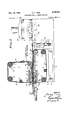
- FIGURE 1 is an end view of the continuous metal casting machine, showing the metal-receiving end thereof with the metal supply nozzle and reservoir removed, and indicating by broken lines the manner in which the upper part of the machine is tilted;
- FIGURE 2 is an enlarged, fragmentary, sectional view, showing the entrance end of the machine, with the metal reservoir and nozzle also shown fragmentarily;
- FIGURE 3 is a longitudinal, sectional view of the machine taken substantially through 3-3 of FIGURE 1;
- FIGURE 4 is an enlarged, fragmentary sectional View taken substantially through 44 of FIGURE 3, showing one of the edge casting assemblies;
- FIGURE 5 is a further enlarged, fragmentary, sectional view through 5-5 of FIGURE'4;
- FIGURE 6 is a fragmentary, sectional view through 6-6 of FIGURE 5;
- FIGURE 7 is a fragmentary, 7-7 of FIGURE 4.
- FIGURE 8 is a substantially diagrammatical plan view of the machine
- FIGURE 9 is a substantially thereof
- FIGURE 10 is a greatly enlarged, fragmentary, front view of one of the guide bars, indicating the ribs therein which tend to spread the casting band;
- FIGURE 11 is a still further enlarged, fragmentary, sectional view thereof, taken through 11-11 of FIGURE 10;
- FIGURE 12 is an enlarged, fragmentary, diagrammatical, plan view of one of the woven casting belts to indicate the manner in which the fabric shrinks longitudinally and transversely with the metal as the metal cools;
- FIGURE 13 is -a greatly exaggerated, fragmentary, sectional view, showing the relationship of a platen, fabric belt, and the metal cast;
- FIGURE 14 is another fragmentary, sectional view, similar to FIGURE 13 but at a reduced scale, showing a modified fabric belt with an underlying metal band.
- the continuous metal casting machine rests on a base frame 1 which includes a pair of spaced vertical plates 2. Inwardly of the vertical plates 2 is a pair of adjustable vertical plates 3, the position of which is determined by adjustment screws 4.
- the adjustable vertical plates 3 support between their upper ends a bottom platen 5 in which is incorporated suitable ducts or a chamber 6 for the circulating of a coolant, such as water.
- a water-cooled drive roller 7 At the forward end of the platen 5 is a semicircular guide bar '8. Below the drive roller 7 and guide bar 8 are guide rollers 9 which, with the drive roller 7 and guide bar 8-, define a rectangle around which is wrapped a casting band Ill.
- the casting band is formed of woven material and will be described in more detail hereinafter.
- a skewing roller 11 Between the guide rollers 9 is a skewing roller 11 which may be positioned slightly out of parallel with the guide rollers 9 so as to effect lateral adjustment of the casting band 10.
- a mounting bracket structure 12 which pivotally supports a frame structure 13 on a pivot shaft 14.
- the frame structure 13 includes spaced side plates 15, which are connected at their lower ends by a top platen 16 similar to the bottom platen 5 except that it is somewhat shorter. Suitable cooling ducts or a cooling chamber 17 are provided within the top platen 16.
- Rearwardly of the top platen 16 is a water-cooled drive sectional view through diagrammatical side view roller 18, and forwardly of the top platen is a semicylindrical guide bar 19 corresponding to the guide bar 8.
- a pair of guide rollers 20 Above the guide bar and drive roller, to define therewith the corner of a rectangle, is a pair of guide rollers 20, and between the guide bar 19 and one of the guide rollers 26 is a skewing roller 21 corresponding to the roller II.
- a casting band Ill identical to the casting band which passes over the bottom platen 5, is wrapped about the drive roller, guide rollers, and guide bar.
- the frame structure 13 may be provided with a counterweight 22 and a suitable tilting screw 23 for the purpose of moving the upper platen 16 and its associated assembly between the solid and broken line positions shown in FIGURE 1.
- each edge casting assembly 26 includes a sprocket wheel 27a and guide wheel 27b around which passes a chain 28.
- the sprocket and guide wheels 27a and 27b have vertical axes, and the axis of the rear or sprocket wheel 27a may coincide with the axis of rotation of the frame structure 25 on the corresponding mounting bracket 24.
- the forward wheel 27b of each edge casting assembly 26 is located slightly forward of the bottom platen 5.
- the plane defined by the wheels 27a and 27b and chain 28 of each assembly lies between the lower and upper casting bands.
- Each chain 28 is provided with a series of edge casting segments 29 so connected to the links of the chain that when the chain is straight the ends of the segments are in contiguous relation with each other.
- One of the reaches of each chain is so positioned that the segments 29 carried thereon may pass between the upper and lower casting bands.
- a bridging frame 30 Extending between the wheels 27a and 27b of each assembly 26 is a bridging frame 30 having a retainer channel 31 adapted to receive a track bar 32, which bears against the backside of the corresponding chain 28 to guide the edge casting segments 29 between the casting bands 10.
- the edge bar is backed by set screws 34-, and its surface confronting the chain is contoured so that with proper adjustment of the set screws the edge casting segments 29 may be moved inwardly so as to pass between the forward and rearward wheels 27a and 27b to compensate for lateral shrinkage of the metal cast therebetween.
- the chains 28 are of the type having rollers 35 which ride on the edge of the track bar.
- the chains may be provided with lugs 36 which overlie and underlie the track bar, as shown best in FIGURE 6.
- One or more of the set screws 34 may project into mating sockets in the track bar 32 so as to restrain the track bar against longitudinal displacement.
- a cross bar 37 Forwardly of the guide bar 8 is a cross bar 37 to which is Welded a lower nozzle block clamp 38 adapted to cooperate with an upper nozzle block clamp 39 to secure a nozzle block 40 therebetween.
- the ends of the clamps 38 and 39 confronting the lower and upper guide bars 8 and 19 are beveled to clear the casting bands 10.
- the nozzle block 40 is formed of suitable heat-resistant material, such as a ceramic material, and is adapted to extend between the casting bands at the region in which the casting bands move onto their respective platens and are in parallel relation.
- the nozzle block 44 is approximately equal in thickness to the thickness of the band of metal to be cast, and is provided with a series of axially extending passages 41.
- the passages near the lateral ends of the nozzle block 40 may diverge so that molten metal may be distributed uniformly across the casting bands.
- the nozzle block is located slightly rearward of the forward wheels 27b of the edge casting assemblies 26, as indicated in FIGURE 4.
- a reservoir 42 Forwardly of the nozzle block 40' is a reservoir 42 having a suitable nozzle 43 which may be brought into registry with the nozzle block 4b, as indicated in FIG- URE 2. Molten metal is supplied in any conventional manner to the reservoir 4-2 and discharged through the nozzle 43 and nozzle block 4Q into the space between the casting bands It and the edge casting segments 29. If desired, a coolant tube 44 may be provided under the lower clamp 38 to minimize warping of the lower clamp, as shown in FIGURE 2.
- the feed control unit 45 Located rearwardly of the mounting brackets 24, that is rearwardly of the drive roller 7, is a feed control unit 45.
- the feed control unit includes framework which supports a set of lower rolls 46 and a set of upper rolls 47. These rolls are so adjusted as to grip opposite surfaces of the cast metal and withdraw the solid metal as it emerges from between the casting bands. Edge rolls 48 are provided to effect lateral adjustment of the solid cast metal passing between the rolls 46 and 47.
- the lower and upper casting units include respectively the bottom platen 5, top platen l6, edge casting assembly 26, and feed control unit and are synchronized in their operations by suitable drive means, indicated in part in FIGURE 1, and may be located at one side of the base frame 1. For purposes of illustration, however, reference is made to the diagrammatical view shown in FIG- URE 9.
- the drive means includes a motor 49 which supplies power to a speed control means 50 having suitable output drives 5-1, 52, and 53 leading respectively to the feed control unit 45, lower drive roller 9, and upper drive roller 18.
- a speed control means 50 having suitable output drives 5-1, 52, and 53 leading respectively to the feed control unit 45, lower drive roller 9, and upper drive roller 18.
- an output drive which includes the bevel gears 54 shown in FIGURE 3, operates the rear sprocket wheels of the edge casting assemblies 26.
- the speeds of the various drives are so coordinated by conventional means that the casting belts and edge casting segments move at essentially the same speed, and the feed control unit 45 is adjusted to remove the cast material at the proper rate to minimize tensile or compression loads on the material as it is being cast.
- the casting bands 10 be formed of 'woven material capable of contracting, both longitudinally and transversely, in correspondence with the shrinkage of the metal as it cools from its molten state to its fully solid state.
- glass cloth may be used as the material comprising the casting bands. This is true even though the glass cloth would soften or weaken if heated to the temperature of the molten aluminum. In practice this does not occur because of the contact between the glass cloth and the cooled platen.
- the glass cloth has insulation properties, nevertheless it is capable of conducting heat at a sufiicie-nt rate to prevent destruction of the surface in contact with the molten metal.
- a single glass cloth belt may last for a continuous run of several days duration without replacement.
- the glass cloth is inherently sufficiently inexpensive to warrant its replacement at the end of each normal run.
- the insulation properties of the glass clot-h diffuse the heat from the molten metal to the chilled platen to the extent that the platen is protected from excessive temperature shock, and consequently the life of the platen is greatly extended.
- the fixed platens reach a stable and constant state of temperature gradient during the casting run, and are not subject to alternate heating and cooling as in the case of the casting bands.
- the Woven fabric offers a particular advantage over a solid or sheet metal band, platen, or roll shell.
- metal band, or the like When such metal band, or the like, is heated on one side and cooled on the other, or a temperature differential is set up, the hot side expands relative to the cool side, and because of its rigid nature the band will raise or buckle away from the cool side. This does not happen with a flexible woven fabric.
- the metal band is restrained against buckling, or if the member is a heavily reinforced platen or roll, the surface still expands and the surface is put into compression. If the surface is repeatedly heated and cooled, thermal fatigue and surface cracking or crazing results. This does not happen with the use of a flexible woven fabric.
- a still further important feature resulting from the use of a woven fabric is, that it is free to contract or shrink in precise correlation with the shrinkage of the metal as it passes from the molten to its fully solid state.
- the metal which does not wet the woven material, bridges over the interstices and, apparently, effects a superficial mechanical interlocking with the surface, so that as each unit of metal corresponding to the distance between adjacent strands of the woven material shrinks, the strands readily move closer together without imparting tensile loads on the metal being cast. This is particularly important during the critical stage wherein the metal is essentially in a semisolid state and almost devoid of tensile strength. At this critical stage, any resistance to shrinkage of the metal will result in improper bonding of the crystals of the metal. In fact, to obtain this unrestrained shrinkage of the metal has been one of the major problems encountered in the use of the conventional casting machine.
- FIGURE 12 In order to visualize the shrinkage of the woven material which occurs both longitudinally and transversely, reference is made to FIGURE 12.
- the strands individually do not change in dimension, but the space between the strands decreases. It is not necessary that the material comprising the strands shrink in proportion to the shrinkage of the cast metal, for the reason that the reduction in space between the strands merely increases slightly the corrugations of the individual strands. No appreciable work is required to accomplish this; therefore, no appreciable resistance to shrinkage is transmitted from the woven material to the cast metal. Correlation of the shrinkage of the woven material and the cast metal is probably enhanced by the fact that the metal in bridging between the strands effects a superficial mechanical interlock as represented by the undulations A of the cast metal B shown in FIGURE 13.
- glass cloth While a wide range of glass cloth may be utilized for the casting bands, one commercial grade of cloth used, because it is readily available, is approximately .0067 in average thickness, and has 32 strands per inch in one direction and 42 strands per inch in the transverse direction. glass.
- metal fabric may be used. It is essential, of course, that whatever material is used for the fabric it must be unwettable by the material being cast. In the use of metal fabric, the metal may have an oxide coating or may be of such an alloy as to resist wetting.
- the outer layer 16a may Each strand, of course, comprises many fibers of be glass cloth or other fabric, whereas the inner layer 16b may be formed of sheet metal.
- the sheet metal in effect becomes a moving platen, and in practice its underside may be in direct contact with a coolant.
- the function of the woven material particularly if this be a material having insulation qualities such as glass cloth, is highly desirable.
- FIG- URES 10 and 11 This means consists essentially in providing rudimentary or shallow grooves 55 on the guide bars 8 and 19. The grooves are directed helically in a right and left direction from the center of the guide bars so as to exert a lateral wiping force on the casting bands It as they pass thereover. It should be noted, however, that glass cloth has inherently a degree of elasticity which in itself tends to function in a manner to effect lateral spreading of the fiber glass cloth, once it is freed from the shrinking effect of the metal.
- the surfaces of the platens be as flat as possible under operating conditions. Even though water cooled, some warping or bowing of the sides receiving heat from the metal occurs. While this may be, in theory, compensated for by initially hollow-grinding the surfaces, it is difiicult to accomplish in practice. Compensation also may be accomplished by placement of strip heaters 56 below and above the platens 5 and 16, respectively. These heaters expand the remote sides of the platen in correspondence with expansion of the proximal sides thereof. By adjusting the heat supplied and judiciously determining the placement of the strip heaters, satisfactory compensation is achieved so that the cross section of the material being cast may be accurately controlled.
- a machine for casting metals in the form of a continuous sheet of substantially greater Width than thickness comprising:
- a horizontal platen having a flat upper surface defining a wide side of a mold cavity
- a woven casting cloth band overlying said platen, said casting cloth being formed of strands that are resistant to damage by the high temperature of the molten metal and non-wettable thereby, and also being limp and flexible, whereby the weight of the molten metal filling the mold cavity presses the casting cloth down into good, heat-conducting contact with said platen;
- casting cloth having interstices and surface irregularities that are impressed upon the surface of the metal when the metal solidifies, whereby the casting cloth is frictionally adhered to the surface of the metal and caused to contract with the metal as the metal shrinks transversely during solidification and cooling;
- a machine for casting metals in the form of a continuous sheet of substantially greater width than thickness comprising:
- a horizontal platen having a flat upper surface defining a wide side of a mold cavity
- a woven casting cloth band overlying said platen, said casting cloth being formed of strands that are resistant to damage by the high temperature of the molten metal and non-wettable thereby, and also being limp and flexible, whereby the weight of the molten metal filling the mold cavity presses the metal and caused to contract with the metal as the metal shrinks during solidification and cooling;
- casting cloth down into good, heat-conducting con- 10 .g. the side margins of said cloth bands being free to tact 'with said platen; slide between said edge dams and the adjacent platen a. said casting cloth having interstices and surface surfaces so as to allow the cloth bands to draw inirregularities that are impressed upon the surface wandly as they are contracted in width by shrinkage of the metal when the metal solidifies, whereby the of the cooling metal; l
- casting cloth is frictionally adhered to the surface h. and means for flattening out and smoothing said of the metal and caused to contract with the metal as the metal shrinks transversely during solidification and cooling;
- edge dams disposed inwardly from a. a pair of opposed horizontal fixed platens having the opposite side edges of said platen and overlying flat parallel confronting surfaces defining the wide the side margins of said casting cloth to define the sides of a horizontal mold cavity; narrow sides of the mold cavity; b. a pair of traveling edge dams disposed along the g. said edge dams following the edge of the cast metal side margins of said platens to define the narrow sides as the latter shrinks transversely and said casting of said mold cavity; cloth correspondingly contracts in width. 0. means for cooling said platens;
- casting cloth having interstices and surface m t l, d readily tm tibl th rewith to prevent irregularities that are impressed upon the s establishment of tension stress in the metal during 0f the me al when he m t l s li fi whereby the its transition from the molten to the solid state;
- Casting cloth is friction-ally adher'id the Surface V 1.
- a machine for casting metals in the form of a continuous sheet of substantially greater width than thickness comprising:
- ha d means flattefllng out and Smoothmg
- said cloth bands being formed of strands that are casting cloth band to 1ts normal uncontracted width resistant to damage by the high temperature f molten metal and non-wettable thereby, and also being limp and flexible, whereby the force exerted by molten metal filling the mold cavity presses the cloth hands into good, heat-conducting contact with said platens, said cloth bands initially forming a temporary skin for the principal surfaces of the molten metal, and readily contractible therewith to prevent establishment of tension stress in the metal during its transition from the molten to the solid state; e. a pair of endless edge dams having reaches disposed between the margins of said cloth bands; means for advancing said cloth bands and edge dams in unison;
- a machine for casting metals in the form of a continuous sheet of substantially greater width than thickness comprising:
- a a pair of opposed spaced platens having parallel flat surfaces defining the wide sides of a mold cavity
- said cloth bands having interstices and surface irregularities that are impressed upon the surface of the metal while the metal is still plastic, whereby the 5' cloth is frictionally adhered to the surface of the with the metal as the metal shrinks transversely during solidification and cooling; h. the side margins of said cloth bands being free to slide between said edge dams and the adjacent platen surfaces so as to allow the cloth bands to draw inwardly as they are contracted in width by shrinkage of the cooling metal;
- said edge dams converging along the line of travel by an amount substantially equal to the contraction in width of the casting cloth
Landscapes
- Engineering & Computer Science (AREA)
- Mechanical Engineering (AREA)
- Continuous Casting (AREA)
Description
Nov. 19,1963 R. T. FAGG 3,110,941
CONTINUOUS METAL CASTING MACHINE Filed'Oct. 3, 1960 5 Sheets-Sheet 1 Eat INVENTOR. fi/fi/AM 777 466 Arrow/v5 Y3 Nov. 19, 1963 R. T. FAGG 3,110,941
con'rmuous METAL CASTING MACHINE Filed Oct. 5. 1960 I 5 Sheets-Sheet 2 WATER COOLED DRIVING ROLLERS INV EN TOR.
Ham/a0 7510s BY 4 rro/e NE ys Nov. 19, 1963 R. T. FAGG commons METAL CASTING MACHINE 5 Sheets-Sheet 3 Filed Oct. 3, 1960 INVENTOR 0 775106 I l L if BY 2 ATTORNEYS O (I v 8. IE
Nov. 19, 1963 R. T. FAGG 3,110,941
CONTINUOUS METAL CASTING MACHINE Filed Oct. 3, 1960 5 Sheets-Sheet 4 Fla. 8
SPEED CONTROL MEANS INVENTOR. BYfi/CHA/EO T/ZGG w ATTORNEYS Nov. 19, 1963 R. T. FYAGG 3,110,941
CONTINUOUS METAL CASTING MACHINE 5 Sheets-Sheet 5 Filed Oct. 3, 1960 METAL BAND/ /a FIG. 11
INVENTOR. f/cHA/b .7 f7! ea A Tree N vs United States Patent 3,110,941 CON'IINUOU METAL CASTING MAEI-IINE Richard Thomas Fagg, Riverside, Calih, assignor, by mesne assignments, to American Metal Climax, Inc, a corporation of New York Filed Oct. 3, 196i), Ser. No. 59,953 7 Claims. (Cl. 22-57.4)
This invention relates to continuous metal casting machines, more particularly to machines wherein the metal is cast in a continuously moving mold chamber formed of top and bottom bands and closed by side bands.
One of the major problems inherent in a conventional metal casting machine utilizing casting bands is apparently due in part to localized buckling of the metal band due to contact with the hot metal. When cold sheet metal, such as a water-cooled band, is brought into contact with the molten metal, the surface of the sheet next to the hot metal becomes hotter than the surface exposed to the cold water. Expansion of the hot sides results in a bowing or buckling of the band in the direction of the hot metal. Simultaneously, the molten metal starts to solidify from its surfaces inward; but because of the buckling of the metal band, heat transfer from the metal to the band is not uniform. This results in an irregular grain growth of the solidifying core of the metal. The nonuniform cooling develops porous spots and a nonuniform density of the cast strip. This is particularly serious if the cast strip is to be fabricated or rolled, as further working cannot be successful.
The problem is compounded by the fact that the metal being cast undergoes substantial shrinkage as it changes from its liquid to its solid state. If the metal being cast is aluminum, it passes through what is termed a hot short state in which maximum shrinkage occurs, and the metal has virtually no tensional strength. This is par- I ticularly true of many high strength aluminum alloys. The frictional contact between the metal casting and the metal is such as to subject the metal being cast to tensional loads sulficient to cause cracking of the product.
The objects of this invention seek to overcome the difficulties outlined, and include:
First, to provide a continuous metal casting machine wherein the upper and lower moving bands are capable of contracting as the metal cools. More particularly, these bands are formed of woven material so that as the metal shrinks in passing from its liquid phase it is not required to slide relative to the casting bands; instead, the casting bands likewise shrink, thus avoiding, or at least minimizing, tension loads on the metal, especially during its hot short period.
Second, to.,provide a continuous metal casting machine which utilizes for the casting bands woven fiberglass backed by a chilling platen, the weave of the fiberglass being superficially interlocked mechanically with the surface of the metal so that the woven fabric gathers uniformly as the metal shrinks, without developing wrinkles.
Third, to provide a continuous metal casting machine wherein the woven fiberglass casting belts functions as a heat barrier to control heat transfer from the molten metal to the platen, to minimize thermal shock on the cooling platen and eliminate thermal fatigue of the surface of the cooling platen; and furthermore controlling the rate of heat extraction from the solidifying metal thereby producing a more uniform grain structure in the cast product.
Fourth, to provide a continuous metal casting machine which incorporates novel edge casting bands or dams which move inward between the top and bottom casting bands to compensate for lateral shrinkage of the metal being cast. 7
Fifth, to provide on the whole a continuous metal cast- 3,11%,94l Patented Nov. 19, 1963 ing machine which produces a particularly uniform, high strength product ideally suitable for further working.
With the above and other objects in view, as may appear hereinafter, reference is directed to the accompanying drawings in which:
FIGURE 1 is an end view of the continuous metal casting machine, showing the metal-receiving end thereof with the metal supply nozzle and reservoir removed, and indicating by broken lines the manner in which the upper part of the machine is tilted;
FIGURE 2 is an enlarged, fragmentary, sectional view, showing the entrance end of the machine, with the metal reservoir and nozzle also shown fragmentarily;
FIGURE 3 is a longitudinal, sectional view of the machine taken substantially through 3-3 of FIGURE 1;
FIGURE 4 is an enlarged, fragmentary sectional View taken substantially through 44 of FIGURE 3, showing one of the edge casting assemblies;
FIGURE 5 is a further enlarged, fragmentary, sectional view through 5-5 of FIGURE'4;
FIGURE 6 is a fragmentary, sectional view through 6-6 of FIGURE 5;
FIGURE 7 is a fragmentary, 7-7 of FIGURE 4;
FIGURE 8 is a substantially diagrammatical plan view of the machine;
FIGURE 9 is a substantially thereof;
FIGURE 10 is a greatly enlarged, fragmentary, front view of one of the guide bars, indicating the ribs therein which tend to spread the casting band;
FIGURE 11 is a still further enlarged, fragmentary, sectional view thereof, taken through 11-11 of FIGURE 10;
FIGURE 12 is an enlarged, fragmentary, diagrammatical, plan view of one of the woven casting belts to indicate the manner in which the fabric shrinks longitudinally and transversely with the metal as the metal cools;
FIGURE 13 is -a greatly exaggerated, fragmentary, sectional view, showing the relationship of a platen, fabric belt, and the metal cast;
FIGURE 14 is another fragmentary, sectional view, similar to FIGURE 13 but at a reduced scale, showing a modified fabric belt with an underlying metal band.
The continuous metal casting machine rests on a base frame 1 which includes a pair of spaced vertical plates 2. Inwardly of the vertical plates 2 is a pair of adjustable vertical plates 3, the position of which is determined by adjustment screws 4. The adjustable vertical plates 3 support between their upper ends a bottom platen 5 in which is incorporated suitable ducts or a chamber 6 for the circulating of a coolant, such as water.
'Rear-wardly of the platen 5 is a water-cooled drive roller 7. At the forward end of the platen 5 is a semicircular guide bar '8. Below the drive roller 7 and guide bar 8 are guide rollers 9 which, with the drive roller 7 and guide bar 8-, define a rectangle around which is wrapped a casting band Ill. The casting band is formed of woven material and will be described in more detail hereinafter. Between the guide rollers 9 is a skewing roller 11 which may be positioned slightly out of parallel with the guide rollers 9 so as to effect lateral adjustment of the casting band 10.
At one side of the vertical plates 2 is a mounting bracket structure 12 which pivotally supports a frame structure 13 on a pivot shaft 14. The frame structure 13 includes spaced side plates 15, which are connected at their lower ends by a top platen 16 similar to the bottom platen 5 except that it is somewhat shorter. Suitable cooling ducts or a cooling chamber 17 are provided within the top platen 16.
Rearwardly of the top platen 16 is a water-cooled drive sectional view through diagrammatical side view roller 18, and forwardly of the top platen is a semicylindrical guide bar 19 corresponding to the guide bar 8. Above the guide bar and drive roller, to define therewith the corner of a rectangle, is a pair of guide rollers 20, and between the guide bar 19 and one of the guide rollers 26 is a skewing roller 21 corresponding to the roller II. A casting band Ill, identical to the casting band which passes over the bottom platen 5, is wrapped about the drive roller, guide rollers, and guide bar. By reason of the fact that the upper platen 16 is shorter than the lower platen 5, the guide rollers 20 are spaced a further distance from the upper platen 16 than the guide rollers 9 with respect to the bottom platen 5, so that identical casting bands 19 may be used.
The frame structure 13 may be provided with a counterweight 22 and a suitable tilting screw 23 for the purpose of moving the upper platen 16 and its associated assembly between the solid and broken line positions shown in FIGURE 1.
Suitably supported by brackets 24 rearwardly of the bottom platen and associated assembly is a pair of frame structures 25, indicated fragmentarily in FIGURE 3, which supports a pair of edge casting assemblies 26 adapted to be pivoted between the solid and broken line positions indicated diagrammatically in FIGURE 8, More particularly, as shown best in FIGURES 4, 5, 6, and 7, each edge casting assembly 26 includes a sprocket wheel 27a and guide wheel 27b around which passes a chain 28.
The sprocket and guide wheels 27a and 27b have vertical axes, and the axis of the rear or sprocket wheel 27a may coincide with the axis of rotation of the frame structure 25 on the corresponding mounting bracket 24. The forward wheel 27b of each edge casting assembly 26 is located slightly forward of the bottom platen 5. The plane defined by the wheels 27a and 27b and chain 28 of each assembly lies between the lower and upper casting bands.
Each chain 28 is provided with a series of edge casting segments 29 so connected to the links of the chain that when the chain is straight the ends of the segments are in contiguous relation with each other. One of the reaches of each chain is so positioned that the segments 29 carried thereon may pass between the upper and lower casting bands.
Extending between the wheels 27a and 27b of each assembly 26 is a bridging frame 30 having a retainer channel 31 adapted to receive a track bar 32, which bears against the backside of the corresponding chain 28 to guide the edge casting segments 29 between the casting bands 10. The edge bar is backed by set screws 34-, and its surface confronting the chain is contoured so that with proper adjustment of the set screws the edge casting segments 29 may be moved inwardly so as to pass between the forward and rearward wheels 27a and 27b to compensate for lateral shrinkage of the metal cast therebetween.
In order to facilitate the use of the track bar 32, the chains 28 are of the type having rollers 35 which ride on the edge of the track bar. In addition, the chains may be provided with lugs 36 which overlie and underlie the track bar, as shown best in FIGURE 6. One or more of the set screws 34 may project into mating sockets in the track bar 32 so as to restrain the track bar against longitudinal displacement.
Forwardly of the guide bar 8 is a cross bar 37 to which is Welded a lower nozzle block clamp 38 adapted to cooperate with an upper nozzle block clamp 39 to secure a nozzle block 40 therebetween. The ends of the clamps 38 and 39 confronting the lower and upper guide bars 8 and 19 are beveled to clear the casting bands 10. The nozzle block 40 is formed of suitable heat-resistant material, such as a ceramic material, and is adapted to extend between the casting bands at the region in which the casting bands move onto their respective platens and are in parallel relation.
The nozzle block 44 is approximately equal in thickness to the thickness of the band of metal to be cast, and is provided with a series of axially extending passages 41. The passages near the lateral ends of the nozzle block 40 may diverge so that molten metal may be distributed uniformly across the casting bands. The nozzle block is located slightly rearward of the forward wheels 27b of the edge casting assemblies 26, as indicated in FIGURE 4.
Forwardly of the nozzle block 40' is a reservoir 42 having a suitable nozzle 43 which may be brought into registry with the nozzle block 4b, as indicated in FIG- URE 2. Molten metal is supplied in any conventional manner to the reservoir 4-2 and discharged through the nozzle 43 and nozzle block 4Q into the space between the casting bands It and the edge casting segments 29. If desired, a coolant tube 44 may be provided under the lower clamp 38 to minimize warping of the lower clamp, as shown in FIGURE 2.
Located rearwardly of the mounting brackets 24, that is rearwardly of the drive roller 7, is a feed control unit 45. The feed control unit includes framework which supports a set of lower rolls 46 and a set of upper rolls 47. These rolls are so adjusted as to grip opposite surfaces of the cast metal and withdraw the solid metal as it emerges from between the casting bands. Edge rolls 48 are provided to effect lateral adjustment of the solid cast metal passing between the rolls 46 and 47.
The lower and upper casting units include respectively the bottom platen 5, top platen l6, edge casting assembly 26, and feed control unit and are synchronized in their operations by suitable drive means, indicated in part in FIGURE 1, and may be located at one side of the base frame 1. For purposes of illustration, however, reference is made to the diagrammatical view shown in FIG- URE 9.
The drive means includes a motor 49 which supplies power to a speed control means 50 having suitable output drives 5-1, 52, and 53 leading respectively to the feed control unit 45, lower drive roller 9, and upper drive roller 18. In addition, an output drive, which includes the bevel gears 54 shown in FIGURE 3, operates the rear sprocket wheels of the edge casting assemblies 26. The speeds of the various drives are so coordinated by conventional means that the casting belts and edge casting segments move at essentially the same speed, and the feed control unit 45 is adjusted to remove the cast material at the proper rate to minimize tensile or compression loads on the material as it is being cast.
It is essential to the operation of the machine that the casting bands 10 be formed of 'woven material capable of contracting, both longitudinally and transversely, in correspondence with the shrinkage of the metal as it cools from its molten state to its fully solid state.
It has been found that, for the purposes of casting aluminum, glass cloth may be used as the material comprising the casting bands. This is true even though the glass cloth would soften or weaken if heated to the temperature of the molten aluminum. In practice this does not occur because of the contact between the glass cloth and the cooled platen.
In other words, although the glass cloth has insulation properties, nevertheless it is capable of conducting heat at a sufiicie-nt rate to prevent destruction of the surface in contact with the molten metal. In practice, a single glass cloth belt may last for a continuous run of several days duration without replacement. The glass cloth is inherently sufficiently inexpensive to warrant its replacement at the end of each normal run.
The insulation properties of the glass clot-h diffuse the heat from the molten metal to the chilled platen to the extent that the platen is protected from excessive temperature shock, and consequently the life of the platen is greatly extended. The fixed platens reach a stable and constant state of temperature gradient during the casting run, and are not subject to alternate heating and cooling as in the case of the casting bands.
The Woven fabric offers a particular advantage over a solid or sheet metal band, platen, or roll shell. When such metal band, or the like, is heated on one side and cooled on the other, or a temperature differential is set up, the hot side expands relative to the cool side, and because of its rigid nature the band will raise or buckle away from the cool side. This does not happen with a flexible woven fabric.
Furthermore, if the metal band is restrained against buckling, or if the member is a heavily reinforced platen or roll, the surface still expands and the surface is put into compression. If the surface is repeatedly heated and cooled, thermal fatigue and surface cracking or crazing results. This does not happen with the use of a flexible woven fabric.
A still further important feature resulting from the use of a woven fabric is, that it is free to contract or shrink in precise correlation with the shrinkage of the metal as it passes from the molten to its fully solid state. The metal, which does not wet the woven material, bridges over the interstices and, apparently, effects a superficial mechanical interlocking with the surface, so that as each unit of metal corresponding to the distance between adjacent strands of the woven material shrinks, the strands readily move closer together without imparting tensile loads on the metal being cast. This is particularly important during the critical stage wherein the metal is essentially in a semisolid state and almost devoid of tensile strength. At this critical stage, any resistance to shrinkage of the metal will result in improper bonding of the crystals of the metal. In fact, to obtain this unrestrained shrinkage of the metal has been one of the major problems encountered in the use of the conventional casting machine.
In order to visualize the shrinkage of the woven material which occurs both longitudinally and transversely, reference is made to FIGURE 12. In shrinking, the strands individually do not change in dimension, but the space between the strands decreases. It is not necessary that the material comprising the strands shrink in proportion to the shrinkage of the cast metal, for the reason that the reduction in space between the strands merely increases slightly the corrugations of the individual strands. No appreciable work is required to accomplish this; therefore, no appreciable resistance to shrinkage is transmitted from the woven material to the cast metal. Correlation of the shrinkage of the woven material and the cast metal is probably enhanced by the fact that the metal in bridging between the strands effects a superficial mechanical interlock as represented by the undulations A of the cast metal B shown in FIGURE 13.
While a wide range of glass cloth may be utilized for the casting bands, one commercial grade of cloth used, because it is readily available, is approximately .0067 in average thickness, and has 32 strands per inch in one direction and 42 strands per inch in the transverse direction. glass.
It should be understood, however, that other weaves of glass cloth may be used. In fact, depending upon the nature of the metal being cast, woven metal fabric may be used. It is essential, of course, that whatever material is used for the fabric it must be unwettable by the material being cast. In the use of metal fabric, the metal may have an oxide coating or may be of such an alloy as to resist wetting.
While it has been found satisfactory to use a casting band solely of woven material, it is possible touse a laminated casting band having an outer layer of woven material and an inner layer of sheet material, as shown in FIGURE 14. In this case, the outer layer 16a may Each strand, of course, comprises many fibers of be glass cloth or other fabric, whereas the inner layer 16b may be formed of sheet metal. The sheet metal in effect becomes a moving platen, and in practice its underside may be in direct contact with a coolant. Inasmuch as thin metal bands are even more subject to thermal shock than a heavy platen, the function of the woven material, particularly if this be a material having insulation qualities such as glass cloth, is highly desirable.
Due to the fact that the metal tends to shrink the casting hands it? laterally, during the casting operation, it is desirable to utilize a conventional means for effecting lateral stretching of the casting bands. t is a conventional practice to provide, in machinery utilizing fabric conveyor bands, or the like, special rollers which are grooved or otherwise arranged to wipe laterally on the cloth to effect this result.
One means of accomplishing this is illustrated in FIG- URES 10 and 11. This means consists essentially in providing rudimentary or shallow grooves 55 on the guide bars 8 and 19. The grooves are directed helically in a right and left direction from the center of the guide bars so as to exert a lateral wiping force on the casting bands It as they pass thereover. It should be noted, however, that glass cloth has inherently a degree of elasticity which in itself tends to function in a manner to effect lateral spreading of the fiber glass cloth, once it is freed from the shrinking effect of the metal.
it is highly desirable that the surfaces of the platens be as flat as possible under operating conditions. Even though water cooled, some warping or bowing of the sides receiving heat from the metal occurs. While this may be, in theory, compensated for by initially hollow-grinding the surfaces, it is difiicult to accomplish in practice. Compensation also may be accomplished by placement of strip heaters 56 below and above the platens 5 and 16, respectively. These heaters expand the remote sides of the platen in correspondence with expansion of the proximal sides thereof. By adjusting the heat supplied and judiciously determining the placement of the strip heaters, satisfactory compensation is achieved so that the cross section of the material being cast may be accurately controlled.
While a particular embodiment of this invention has been shown and described, it is not intended to limit the same to the exact details of the construction set forth, and it embraces such changes, modifications, and equivalents of the parts and their formation and arrangement as come within the purview of the appended claims.
What is claimed is:
1. A machine for casting metals in the form of a continuous sheet of substantially greater Width than thickness, comprising:
a. a horizontal platen having a flat upper surface defining a wide side of a mold cavity;
b. means for cooling said cavity;
c. a woven casting cloth band overlying said platen, said casting cloth being formed of strands that are resistant to damage by the high temperature of the molten metal and non-wettable thereby, and also being limp and flexible, whereby the weight of the molten metal filling the mold cavity presses the casting cloth down into good, heat-conducting contact with said platen;
(I. said casting cloth having interstices and surface irregularities that are impressed upon the surface of the metal when the metal solidifies, whereby the casting cloth is frictionally adhered to the surface of the metal and caused to contract with the metal as the metal shrinks transversely during solidification and cooling;
6. and means for advancing said casting cloth at a uniform rate.
2. A machine for casting metals in the form of a continuous sheet of substantially greater width than thickness, comprising:
a. a horizontal platen having a flat upper surface defining a wide side of a mold cavity;
b. means for cooling said cavity;
0. a woven casting cloth band overlying said platen, said casting cloth being formed of strands that are resistant to damage by the high temperature of the molten metal and non-wettable thereby, and also being limp and flexible, whereby the weight of the molten metal filling the mold cavity presses the metal and caused to contract with the metal as the metal shrinks during solidification and cooling;
. means for advancing said cloth :bands at a uniform rate in the same direction for continuous entrance of said cloth bands into said mold cavity;
7. a pair of edge dams disposed between said cloth bands and also between said platens inwardly from the side edges of said cloth bands and platens there by to define the narrow sides of the mold cavity;
casting cloth down into good, heat-conducting con- 10 .g. the side margins of said cloth bands being free to tact 'with said platen; slide between said edge dams and the adjacent platen a. said casting cloth having interstices and surface surfaces so as to allow the cloth bands to draw inirregularities that are impressed upon the surface wandly as they are contracted in width by shrinkage of the metal when the metal solidifies, whereby the of the cooling metal; l
casting cloth is frictionally adhered to the surface h. and means for flattening out and smoothing said of the metal and caused to contract with the metal as the metal shrinks transversely during solidification and cooling;
e. means for advancing said casting cloth at a unif. a pair of traveling edge dams disposed inwardly from the opposite side edges of said platen and overlying the side margins of said casting cloth to define the narrow sides of the mold cavity;
g. said edge dams advancing with said casting cloth before again entering said mold cavity.
cloth bands to their normal uncontracted width hefore again entering said mold cavity. 5. A machine for casting metals in the form of a continuous sheet of substantially greater width than thickness,
form rate; 2 comprising:
1. and a pair of edge dams disposed inwardly from a. a pair of opposed horizontal fixed platens having the opposite side edges of said platen and overlying flat parallel confronting surfaces defining the wide the side margins of said casting cloth to define the sides of a horizontal mold cavity; narrow sides of the mold cavity; b. a pair of traveling edge dams disposed along the g. said edge dams following the edge of the cast metal side margins of said platens to define the narrow sides as the latter shrinks transversely and said casting of said mold cavity; cloth correspondingly contracts in width. 0. means for cooling said platens;
A machine for Casting metals in the form of a d. a pair of endless woven cloth bands covering said continuous sheet of substantially greater width than thickplatens, the side margins of said cloth bands being ness, comprising: interposed between and freely slidable with respect a. a horizontal platen having a flat upper surface to said platens and edge dams to permit free longidefining a wide side of a mold cavity; tudinal travel and transverse contraction of the cloth b. means for cooling said cavity; bands with respect to the surface of the platens;
c. an endless woven casting cloth band overlying said 6. said loth b d being formed of strands that are platen, Said g 610th being fofmfld 0f Strands resistant to damage by the high temperature of that are ffisistan'i damage y the high p molten metal and non-wettable thereby, and also beture of the molt n metal and ll n-w i a y, ing limp and flexible, whereby the force exerted by and also being limp and flexible, whereby the weight molten metal filling the mold cavity presses the cloth of molten metal filling the mold cavity pr ss s the bands into good, heat-conducting contact with said Sting 010th dOWIl into good, heat-Conducting C011- 40 platens, said cloth bands initially forming a tempotact with said platen; rary skin for the principal surfaces of the molten (I. said casting cloth having interstices and surface m t l, d readily tm tibl th rewith to prevent irregularities that are impressed upon the s establishment of tension stress in the metal during 0f the me al when he m t l s li fi whereby the its transition from the molten to the solid state; Casting cloth is friction-ally adher'id the Surface V 1. means for advancing said cloth bands and said travelof the metal and caused to contract with the metal j edgg d over id platens t a if r r t iasthe metal shrinks transversely during solidification d i th same di ti and cooling; g. and means for flattening out and smoothing said e. means for advancing said casting cloth at a uniform 1 h b d to h i normal gt d idth b rate for continuous entry into said mold cavity; fore again entering said mold cavity.
6. A machine for casting metals in the form of a continuous sheet of substantially greater width than thickness, comprising:
a. a pair of opposed horizontal fixed platens having flat confronting surfaces;
and converging along the line of travel thereof by 50 means f cooling Said platens; an am u subsiafllally fiqllal to the contraction c. a pair of endless woven cloth bands having reaches Width of the casting cloth; covering said platens;
ha d means flattefllng out and Smoothmg (I. said cloth bands being formed of strands that are casting cloth band to 1ts normal uncontracted width resistant to damage by the high temperature f molten metal and non-wettable thereby, and also being limp and flexible, whereby the force exerted by molten metal filling the mold cavity presses the cloth hands into good, heat-conducting contact with said platens, said cloth bands initially forming a temporary skin for the principal surfaces of the molten metal, and readily contractible therewith to prevent establishment of tension stress in the metal during its transition from the molten to the solid state; e. a pair of endless edge dams having reaches disposed between the margins of said cloth bands; means for advancing said cloth bands and edge dams in unison;
said cloth bands being frictionally adhered to the surface of the metal and caused to contract in width 4. A machine for casting metals in the form of a continuous sheet of substantially greater width than thickness, comprising:
a. a pair of opposed spaced platens having parallel flat surfaces defining the wide sides of a mold cavity;
b. means for cooling said platens;
c. a pair of endless Woven cloth bands overlying said flat surfaces of said platens and slidable relative thereto, said cloth bands being formed of strands that are resistant to damage by the high temperature of the molten metal and non-wettable thereby;
d. said cloth bands having interstices and surface irregularities that are impressed upon the surface of the metal while the metal is still plastic, whereby the 5' cloth is frictionally adhered to the surface of the with the metal as the metal shrinks transversely during solidification and cooling; h. the side margins of said cloth bands being free to slide between said edge dams and the adjacent platen surfaces so as to allow the cloth bands to draw inwardly as they are contracted in width by shrinkage of the cooling metal;
'. said edge dams converging along the line of travel by an amount substantially equal to the contraction in width of the casting cloth;
'. and means for flattening out and smoothing said cloth bands to their normal uncontracted width before again entering said mold cavity.
. A machine as set forth in claim 6, wherein: a feed spout extends into the entrance end of said mold cavity between said cloth bands and edge dams, said spout being spaced from said platens to provide sliding engagement therewith.
References Cited in the file of this patent UNITED STATES PATENTS 315,045 Lyman Apr. 7, 1885 2,639,490 Brennan May 26, 1953 2,640,235 Hazelett June 2, 1953 2,852,821 Pond Sept. 23, 1958 2,973,563 Leaberry et al. Mar. 7, 1961 FOREIGN PATENTS 15,105 Great Britain Oct. 29, 1908 108,184 Australia Aug. 6, 1939 383,313 Italy Oct. 2, 1940
Claims (1)
1. A MACHINE FOR CASTING METALS IN THE FORM OF A CONTINUOUS SHEET OF SUBSTANTIALLY GREATER WIDTH THAN THICKNESS, COMPRISING: A. A HORIZONTAL PLATEN HAVING A FLAT UPPER SURFACE DEFINING A WIDE SIDE OF A MOLD CAVITY; B. MEANS FOR COOLING SAID CAVITY; C. A WOVEN CASTING CLOTH BAND OVERLYING SAID PLATEN, SAID CASTING CLOTH BEING FORMED OF STRANDS THAT ARE RESISTANT TO DAMAGE BY THE HIGH TEMPERATURE OF THE MOLTEN METAL AND NON-WETTABLE THEREBY, AND ALSO BEING LIMP AND FLEXIBLE, WHEREBY THE WEIGHT OF THE MOLTEN METAL FILLING THE MOLD CAVITY PRESSES THE CASTING CLOTH DOWN INTO GOOD, HEAT-CONDUCTING CONTACT WITH SAID PLATEN;
Priority Applications (3)
| Application Number | Priority Date | Filing Date | Title |
|---|---|---|---|
| US59953A US3110941A (en) | 1960-10-03 | 1960-10-03 | Continuous metal casting machine |
| CH379063A CH395440A (en) | 1960-10-03 | 1963-03-26 | Metal casting process and machine for implementing this process |
| GB11849/63A GB1036472A (en) | 1960-10-03 | 1963-03-26 | Improvements in or relating to continuous metal casting machines |
Applications Claiming Priority (1)
| Application Number | Priority Date | Filing Date | Title |
|---|---|---|---|
| US59953A US3110941A (en) | 1960-10-03 | 1960-10-03 | Continuous metal casting machine |
Publications (1)
| Publication Number | Publication Date |
|---|---|
| US3110941A true US3110941A (en) | 1963-11-19 |
Family
ID=22026379
Family Applications (1)
| Application Number | Title | Priority Date | Filing Date |
|---|---|---|---|
| US59953A Expired - Lifetime US3110941A (en) | 1960-10-03 | 1960-10-03 | Continuous metal casting machine |
Country Status (1)
| Country | Link |
|---|---|
| US (1) | US3110941A (en) |
Cited By (19)
| Publication number | Priority date | Publication date | Assignee | Title |
|---|---|---|---|---|
| US3258812A (en) * | 1964-07-30 | 1966-07-05 | Specialty Converters | Casting belt for foam making apparatus |
| US3281894A (en) * | 1964-10-02 | 1966-11-01 | Buff Fred | Manufacture of expanded cellular products |
| US3295173A (en) * | 1964-03-23 | 1967-01-03 | New York Wire Company | Casting machine for clad metal bars |
| US3295174A (en) * | 1965-03-09 | 1967-01-03 | New York Wire Company | Casting machine for clad metal bars |
| US3343590A (en) * | 1965-02-24 | 1967-09-26 | Continental Oil Co | Continuous horizontal casting in a sacrificial web |
| US3368607A (en) * | 1965-10-22 | 1968-02-13 | Kaiser Aluminium Chem Corp | Method for preventing metal-liquid explosions in casting operation |
| US3399426A (en) * | 1964-10-05 | 1968-09-03 | Advance Ind Inc | Method of and apparatus for extruding thermoplastic material |
| US3422178A (en) * | 1965-10-12 | 1969-01-14 | Monsanto Co | Continuous polymer casting machine and process |
| US3426836A (en) * | 1964-12-11 | 1969-02-11 | Alusuisse | Machine for the continuous casting of slabs between bands |
| US3430683A (en) * | 1967-01-12 | 1969-03-04 | American Metal Climax Inc | Feed tip for continuous strip casting machine |
| US3642055A (en) * | 1969-12-29 | 1972-02-15 | Reynolds Metals Co | Method of and apparatus for continuously casting molten metal |
| US3700027A (en) * | 1970-09-16 | 1972-10-24 | Maanesmann Ag | Continuous casting machine |
| US3703204A (en) * | 1970-10-27 | 1972-11-21 | David W Brownstein | Integrated in-line method of continuously casting metal |
| US3933193A (en) * | 1971-02-16 | 1976-01-20 | Alcan Research And Development Limited | Apparatus for continuous casting of metal strip between moving belts |
| FR2389434A1 (en) * | 1977-05-05 | 1978-12-01 | Prolizenz Ag | |
| US4222431A (en) * | 1977-07-04 | 1980-09-16 | Alcan Research And Development Limited | Continuous casting with resilient strip-edge gripping means |
| DE3406730A1 (en) * | 1984-02-24 | 1985-08-29 | Mannesmann AG, 4000 Düsseldorf | Method and apparatus for the continuous casting of metals, especially steel |
| US4649983A (en) * | 1983-10-26 | 1987-03-17 | Allied Corporation | Chill roll casting of metal strip |
| US5643371A (en) * | 1995-06-07 | 1997-07-01 | Reynolds Metals Company | Method and apparatus for continuously cladding and hot working cast material |
Citations (6)
| Publication number | Priority date | Publication date | Assignee | Title |
|---|---|---|---|---|
| US315045A (en) * | 1885-04-07 | Nathan e | ||
| GB190815105A (en) * | 1908-07-16 | 1908-10-29 | James Draper Bishop | Improvements in or relating to the Manufacture of Sheet Metal. |
| US2639490A (en) * | 1948-08-12 | 1953-05-26 | Joseph B Brennan | Formation of metal strip under controlled pressures |
| US2640235A (en) * | 1949-06-02 | 1953-06-02 | Clarence W Hazelett | Metal manufacturing apparatus |
| US2852821A (en) * | 1954-12-20 | 1958-09-23 | Olin Mathieson | Casting apparatus |
| US2973563A (en) * | 1958-10-27 | 1961-03-07 | Int Nickel Co | Lining for ingot molds and method of producing ingots |
-
1960
- 1960-10-03 US US59953A patent/US3110941A/en not_active Expired - Lifetime
Patent Citations (6)
| Publication number | Priority date | Publication date | Assignee | Title |
|---|---|---|---|---|
| US315045A (en) * | 1885-04-07 | Nathan e | ||
| GB190815105A (en) * | 1908-07-16 | 1908-10-29 | James Draper Bishop | Improvements in or relating to the Manufacture of Sheet Metal. |
| US2639490A (en) * | 1948-08-12 | 1953-05-26 | Joseph B Brennan | Formation of metal strip under controlled pressures |
| US2640235A (en) * | 1949-06-02 | 1953-06-02 | Clarence W Hazelett | Metal manufacturing apparatus |
| US2852821A (en) * | 1954-12-20 | 1958-09-23 | Olin Mathieson | Casting apparatus |
| US2973563A (en) * | 1958-10-27 | 1961-03-07 | Int Nickel Co | Lining for ingot molds and method of producing ingots |
Cited By (19)
| Publication number | Priority date | Publication date | Assignee | Title |
|---|---|---|---|---|
| US3295173A (en) * | 1964-03-23 | 1967-01-03 | New York Wire Company | Casting machine for clad metal bars |
| US3258812A (en) * | 1964-07-30 | 1966-07-05 | Specialty Converters | Casting belt for foam making apparatus |
| US3281894A (en) * | 1964-10-02 | 1966-11-01 | Buff Fred | Manufacture of expanded cellular products |
| US3399426A (en) * | 1964-10-05 | 1968-09-03 | Advance Ind Inc | Method of and apparatus for extruding thermoplastic material |
| US3426836A (en) * | 1964-12-11 | 1969-02-11 | Alusuisse | Machine for the continuous casting of slabs between bands |
| US3343590A (en) * | 1965-02-24 | 1967-09-26 | Continental Oil Co | Continuous horizontal casting in a sacrificial web |
| US3295174A (en) * | 1965-03-09 | 1967-01-03 | New York Wire Company | Casting machine for clad metal bars |
| US3422178A (en) * | 1965-10-12 | 1969-01-14 | Monsanto Co | Continuous polymer casting machine and process |
| US3368607A (en) * | 1965-10-22 | 1968-02-13 | Kaiser Aluminium Chem Corp | Method for preventing metal-liquid explosions in casting operation |
| US3430683A (en) * | 1967-01-12 | 1969-03-04 | American Metal Climax Inc | Feed tip for continuous strip casting machine |
| US3642055A (en) * | 1969-12-29 | 1972-02-15 | Reynolds Metals Co | Method of and apparatus for continuously casting molten metal |
| US3700027A (en) * | 1970-09-16 | 1972-10-24 | Maanesmann Ag | Continuous casting machine |
| US3703204A (en) * | 1970-10-27 | 1972-11-21 | David W Brownstein | Integrated in-line method of continuously casting metal |
| US3933193A (en) * | 1971-02-16 | 1976-01-20 | Alcan Research And Development Limited | Apparatus for continuous casting of metal strip between moving belts |
| FR2389434A1 (en) * | 1977-05-05 | 1978-12-01 | Prolizenz Ag | |
| US4222431A (en) * | 1977-07-04 | 1980-09-16 | Alcan Research And Development Limited | Continuous casting with resilient strip-edge gripping means |
| US4649983A (en) * | 1983-10-26 | 1987-03-17 | Allied Corporation | Chill roll casting of metal strip |
| DE3406730A1 (en) * | 1984-02-24 | 1985-08-29 | Mannesmann AG, 4000 Düsseldorf | Method and apparatus for the continuous casting of metals, especially steel |
| US5643371A (en) * | 1995-06-07 | 1997-07-01 | Reynolds Metals Company | Method and apparatus for continuously cladding and hot working cast material |
Similar Documents
| Publication | Publication Date | Title |
|---|---|---|
| US3110941A (en) | Continuous metal casting machine | |
| US3426836A (en) | Machine for the continuous casting of slabs between bands | |
| ES2210398T3 (en) | CONTINUOUS AND METHOD COLADA MACHINE. | |
| EP0351785B1 (en) | Method and apparatus for introducing differential stresses during manufacture of endless flexible metallic casting belts for enhancing belt performance in continuous metal casting machines | |
| US4062235A (en) | Twin-belt continuous casting wherein the belts are sensed by mechanical probes | |
| US3264856A (en) | Hot strip mill | |
| US7823623B2 (en) | Belt casting machine having adjustable contact length with cast metal slab | |
| US3142873A (en) | Continuous metal casting apparatus | |
| KR101185393B1 (en) | Method and device for equalization of the heat transfer of a cast product during the solidification thereof on a metal conveyor belt of a horizontal strip casting system | |
| US3482620A (en) | Apparatus for continuous metal casting | |
| US3709281A (en) | Machine with horizontally or inclined disposed caterpillar mold for the downward casting of non-ferrous metals | |
| KR102538557B1 (en) | Short belt side dam for twin belt casting machine | |
| US1928562A (en) | Mantjfacttoe of metal billets | |
| US3799239A (en) | Method for continuous casting of metal | |
| ES8400903A1 (en) | Method and apparatus for shaping the casting region in a twin-belt continuous casting machine. | |
| US2108070A (en) | Method of and apparatus for shaping plastic materials | |
| JPH0698464B2 (en) | Belt deformation prevention device for belt type continuous casting machine | |
| JPS6336867B2 (en) | ||
| JP2582952B2 (en) | Metal ribbon continuous casting machine | |
| JPS59199145A (en) | Long side synchronous continuous casting machine | |
| Molotilov et al. | A Study of Structure Formation With the Twin Roll Method of Rapid Quenching | |
| JPH03114632A (en) | Short side plate of continuous thin slab casting machine | |
| KR19980702508A (en) | Continuous casting plant | |
| JPS61195764A (en) | Method and device for controlling pouring rate of continuous casting machine for thin sheet | |
| JPS5947047A (en) | Belt type continuous casting device for thin sheet |